See also on Bedini’s website: http://www.icehouse.net/john34/intro.html
I have been working in the energy field for over 30 years, I have come to the conclusion that their is no “Free Electricity”. This means no Free Energy or Over Unity. Their is only a potential radiant charge that makes up a dipole.
This energy makes up everything we touch and use in our electrical circuits as we know them. The electrical circuits as we know them are flawed, meaning they burn up the dipole that is free in nature.
If you kill the dipole you loose the energy. The dipole killer is the electron current in the circuit. So therefore the term free electricity only applies to those that have done away with the current or have figured a way to block it from completing it’s path through the circuit. Their are no meters to measure this radiant current, and when you catch it, it has the power of the universe and beyond. Good luck in your research . Their is only energy from the vacuum, known as radiant energy.
To find out more about this you need to read Tom Bearden’s book.
# and see also: John C. Bedini: Motor / Generator by Rexresearch.com http://www.rexresearch.com/bedini/bedini.htm
2001, WO 01/52390 A1
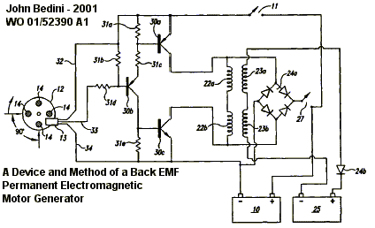
19 July 2001. A device and method of a back EMF permanent electromagnetic motor generator
By Bedini Technology Inc., 2619 Seltice Way, Coeur d’Alene, ID 83814
Abstract: This invention is a back EMF permanent electromagnetic motor generator and method using a regauging process for capturing available electromagnetic energy in the system.
The device is comprised of a rotor with magnets of the same polarity; a timing wheel in apposition to a magnetic Hall Effect pickup switch semiconductor; and a rotor comprised of two bars connected by a permanent magnet with magnetized pole pieces at one end of each bar.
There are input and output coils created by wrapping each bar with a conducting material such as copper wire. Energy from the output coils is transferred to a recovery rectifier or diode.
The magnets of the rotor, which is located on a shaft along with the timing wheel, are in apposition to the magnetized pole pieces of the two bars. The invention works through a process of regauging, that is, the flux fields created by the coils is collapsed because of a reversal of the magnetic field in the magnetized pole pieces thus allowing the capture of available back EMF energy.
Additional available energy may be captured and used to re-energize the battery, and/or sent in another direction to be used as work. As an alternative, the available back EMF energy may be dissipated into the system.
2002, USP # 6,392,370
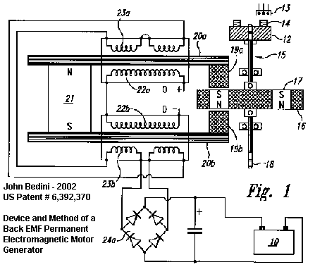
May 21, 2002, Device and Method of a Back EMF Permanent Electromagnetic Motor Generator
By John Bedini
– more details in Patric Kelly pdf file ‘D3’ : http://panacea-bocaf.org/files/patrickkelly/PatD6.pdf
Abstract: This invention is a back EMF permanent electromagnetic motor generator and method using a regauging process for capturing available electromagnetic energy in the system. The device is comprised of a rotor with magnets of the same polarity; a timing wheel in apposition to a magnetic Hall Effect pickup switch semiconductor; and a stator comprised of two bars connected by a permanent magnet with magnetized pole pieces at one end of each bar. There are input and output coils created by wrapping each bar with a conducting material such as copper wire. Energy from the output coils is transferred to a recovery rectifier or diode. The magnets of the rotor, which is located on a shaft along with the timing wheel, are in apposition to the magnetized pole pieces of the two bars. The invention works through a process of regauging, that is, the flux fields created by the coils is collapsed because of a reversal of the magnetic field in the magnetized pole pieces thus allowing the capture of available back EMP energy. Additional available energy may be captured and used to re-energize the battery, and/or sent in another direction to be used as work. As an alternative, the available back EMF energy may be dissipated into the system.
References Cited:U.S. Patent Documents:
– 2,560,260 – Jul., 1951 – Sturtevant, et al.
– 2,613,246 – Oct., 1952 – Spodig
– 2,974,981 – Mar., 1961 – Vervest, et al.
– 4,222,021 – Sep., 1980 – Bunker, Jr.
– 4,265,746 – May., 1981 – Zimmerman, Sr., et al.
– 4,265,754 – May., 1981 – Menold
– 4,417,167 – Nov., 1983 – Ishii, et al.
– 4,423,343 – Dec., 1983 – Field, II.
– 4,429,263 – Jan., 1984 – Miiller
– 4,433,260 – Feb., 1984 – Weisbord, et al.
– 4,488,075 – Dec., 1984 – DeCesare
– RE31,950 – Jul., 1985 – Binns
– 4,536,230 – Aug., 1985 – Landa, et al.
– 4,761,590 – Aug., 1988 – Kaszman
– 4,916,346 – Apr., 1990 – Kliman
– 4,972,112 – Nov., 1990 – Kim
– 4,980,595 – Dec., 1990 – Arora
– 5,130,595 – Jul., 1992 – Arora
– 5,177,054 – Jan., 1993 – Lloyd, et al.
– 5,227,702 – Jul., 1993 – Nahirney
– 5,334,894 – Aug., 1994 – Nakagawa
– 5,350,958 – Sep., 1994 – Ohnishi
– 5,356,534 – Oct., 1994 – Zimmerman, et al.
– 5,369,325 – Nov., 1994 – Nagate, et al.
– 5,371,426 – Dec., 1994 – Nagate, et al.
– 5,451,825 – Sep., 1995 – Strohm
– 5,508,575 – Apr., 1996 – Elrod, Jr.
– 5,514,923 – May., 1996 – Gossler, et al.
– 5,528,113 – Jun., 1996 – Boys, et al. – 318/16.
– 5,532,532 – Jul., 1996 – DeVault, et al.
– 5,731,645 – Mar., 1998 – Clifton, et al. 310/74.
– 6,118,202 – Sep., 2000 – Pinkerton – 310/178.
Foreign Patent Documents: – 0 462,340 Dec., 1991 EP.- 0 932 248 Jul., 1999 EP.- 2 224,398 May., 1990 GB. – WO 99/38,247 Jul., 1999 WO.
Description: BACKGROUND OF THE INVENTION
1. Field of the Invention: The invention relates generally to the capturing of electromagnetic energy using a method and device to create back EMF (electromagnetic force) and re-phasing of the back EMF to recycle and capture the available back EMF energy. Back EMF is also referred to as regauging and may be defined as energy created by the magnetic field from coils, and only by coils, and not by magnets.
2002, USP # 0130,633 A1, WO 02/073779 A1
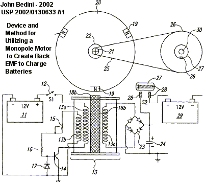
Sep. 19 2002, Device and Method for Utilizing a Monopole Motor to Create Back EMF to Charge Batteries
By John C. Bedini
Abstract: A back EMF monopole motor and method using a rotor containing magnets all of the same polarity and in a monopole condition when in momentary apposition with a magnetized pole piece of a stator having the same polarity, said stator comprised of a coil with three windings: a power-coil winding, a trigger-coil winding, and a recovery-coil winding. The back EMF energy is rectified using a high voltage bridge, which transfers the back EMF energy to a high voltage capacitor for storage in a recovery battery. The stored energy can then be discharged across the recovery battery through the means of a contact rotot switch for further storage.
Technical Field:
(0001) The invention relates generally to the capturing of available electromagnetic energy using a device and method for creating an electromagnetic force (hereinafter, EMF) and then using the available stored energy for recycling into the system as stored energy. The method of creating back EMF is the result of coupling/uncoupling a voltage source to and from a coil.
Background
(002) Operation of present day normal magnetic motors has the rotor pole attracting the stator pole, resulting in the generation of mechanical power from the magnets to the rotor and flywheel. During this phase, energy flows from the magnetics to the rotor/flywheel and is stored as kinetic energy in the increased rotation. A rotor pole leaving a stator pole and creating a condition of ‘drag’ results in power having to be put back into the magnetic section by the rotor and flywheel to forcibly overcome the drag. In a perfect, friction-free motor, the net force field is therefore referred to as ‘most conservative’. A most conservative EMF motor has maximum efficiency. Without extra energy continually fed to the motor, no net work can be done by the magnetic field, since half the time the magnetic field adds energy to the load (the rotor and flywheel) and the other half of the time it substracts energy back from the load (the rotor and flywheel).
Therefore, the total net energy output is zero in any such rotary process without additional energy input. To use a present day magnetic motor, continuous energy must be input into the motor to overcome drag and to power the motor and its load.
(0003) Motors and generators presently in use, all use such conservative fields and therefore, have internal losses. Hence, it is necessary to continually input all of the energy that the motor outputs to the load, plus more energy to cover losses inside the motor itself. EMF motors are rated for efficiency and performance by how much energy ‘input’ into the motor actually results in ‘output’ energy to the load. Normally, the Coefficient of Performance (hereinafter, COP) rating is used aas a measure of efficiency. The COP is the actual output energy going into the load and powering it, divided by the energy that must be input into the device with its motor/load combination. If there were zero internal losses in a motor, that ‘perfect’ motor would have a COP equal to 1,0. That is, all energy input into the motor would be output by the motor directly into the load, and none of the input energy would be lost or dissipated in the motor itself.
(004) In magnetic motor generators presently in use, however, due to friction and design flaws, there are always internal losses and inefficiencies. Some of the energy input into the motor is dissipated in this internal losses. As a consequence, the energy that gets to the load is always less than the input energy. So a standard motor operates with a COP of less than 1.0, which is expressed as COP
(0005) The conservative field inside of a motor itself is divided into two phases. Producing a conservative field involves net symmetry between the ‘power out’ phase from the magnetics to the rotor/flywheel back to the magnetics. That is, the two flows of energy (one from the magnetics into the rotor and flywheel, and one from the rotor and flywheel back to the magnetics) are identical in magnitude but opposite in direction. Each phase alone is said to be ‘asymmetrical’, that is, it either has: 1) a net energy flow out to the rotor/flywheel; or 2) a net energy flow back into the magnetics from the rotor/flywheel. In simplified terms, it is referred to as ‘power out’ and ‘power back in’ phases with respect to the motor magnetics.
(0006) For the power-out phase, energy is derived from the EMF existing between the stator pole and incoming rotor pole in an attraction mode. In this phase, the rotary motion (angular momentum and kinetic energy) of the rotor and flywheel is increased. In short, power is added to the rotor/flywheel (and thus to the load) from the fields between stator pole and rotor pole (the electromagnetic aspects of the system).
(0007) For the ‘power back in’ phase, energy must be fed back into the magnetics from the rotor and flywheel (and the load) to overcome the drag forces existing between stator pole and outgoing rotor pole. In this phase, energy is returned back to the internal magnetic system from the rotary motion of the rotor and flywheel (the angular momentum, which is the rotational energy x time). As is well known in physics, a rotor/flywheel’s angular momentum provides a convenient way to store energy with the spinning rotor/flywheel mass acting as an energy reservoir.
(0008) Most present day conventional magnetic motors use various methods for overcoming and partially reversing back EMF. Back EMF may be defined as the return pulse from the coil out of phase and is the result of regauging, which is the process of reversing the magnetics polarity, that is, from North to South, etc. The back EMF is shorted out and the rotor is attracted back in, therefore eliminating drag. This can be accomplished by pouring in more energy, which overpowers the back EMF, thereby producing a forward EMF in that region. The energy required for this method is furnished by the operator.
(0009) It is well known in the art that changing the voltage alone creates a back EMF and requires no work. This is because to change the potential energy does not require changing the form of that potential energy, but only its magnitude. Work is the changing of the form of energy. Therefore, as long as the form of the potential energy is not changed, the magnitude can be changed without having to perform work in the process. The motor of the present invention takes advantage of this permissible operation to create back EMF asymmetrically, and thereby change its own usable available potential energy.
(0010) In an electric power system, the potential (voltage) is changed by inputting energy to do work on the internal charges of the generator or battery. This potential energy is expended within the generator (or battery) to force the internal charges apart, forming a source dipole. Then the external closed circuit system connected to that source dipole ineptly pumps the spent electrons in the ground line back through the back EMF of the source dipole, thereby scattering the charges and killing the dipole. This shuts off the energy flow from the source dipole to the external circuit. As a consequence of this conventional method, it is a requirement to input and replace additional energy to again restore the dipole. The circuits currently utilized in most electrical generators have been designed to keep on destroying the energy flow by continually scattering all of the dipole charges and terminating the dipole. Therefore, it is necessary to keep on inputing energy to the generator to keep restoring its source dipole.
(0011) A search of prior art failed to reveal any monopole motor devices and methods that recycle available energy from back EMF to charge a battery or provide electrical energy for other uses as described in the present invention. However, the following prior art patents were reviewed:
(0012) USP 4,055,789 to Lasater, Battery Operated Motor with Back EMF Charging.
(0013) USP 2,279,690 to Z. T. Lindsey, Combination Motor Generator.
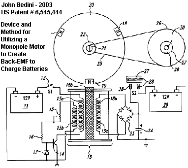
2003, USP # 6,545,444,
April 8, 2003. Device and Method for Utilizing a Monopole Motor to Create Back-EMF to Charge Batteries
By John C. Bedini , Bedini Technology, Inc. (Couer d’Alene, ID)
– more details in Patric Kelly pdf file ‘D3’ : http://panacea-bocaf.org/files/patrickkelly/PatD5.pdf
Abstract: A back EMF monopole motor and method using a rotor containing magnets all of the same polarity and in a monopole condition when in momentary apposition with a magnetized pole piece of a stator having the same polarity, said stator comprised of a coil with three windings: a power-coil winding, a trigger-coil winding, and a recovery-coil winding. The back EMF energy is rectified using a high voltage bridge, which transfers the back EMF energy to a high voltage capacitor for storage in a recovery battery. The stored energy can then be discharged across the recovery battery through the means of a contact rotor switch for further storage.
References Cited U.S. Patent Documents:
– 2279690 – Apr., 1942 – Lindsey
– 4055789 – Oct., 1977 – Lasater
– 4893067 – Jan., 1990 – Bhagwat et al. – 318/599
– 5377094 – Dec., 1994 – Williams et al. – 318/434
– 6037728 – Mar., 2000 – Petkovic – 318/139
– 6116368 – Sep., 2000 – Lyons et al. – 180/165
Description: TECHNICAL FIELD
The invention relates generally to the capturing of available electromagnetic energy using a device and method for creating an electromagnetic force (hereinafter, EMF) and then using the available stored energy for recycling into the system as stored energy. The method of creating back EMF is the result of coupling/uncoupling a voltage source to and from a coil.
SUMMARY OF THE INVENTION
An aspect of the device and method of the present invention is a new monopole electromagnetic motor that captures back EMF energy. The captured back EMF energy maybe used to charge or store electrical energy in a recovery battery. The amount of energy recoverable, as expressed in watts, is dependent upon the configuration, circuitry, switching elements and the number and size of stators, rotors, magnets and coils that comprise the motor.
The motor uses a small amount of energy from a primary battery to “trigger” a larger input of available energy by supplying back EMF, thus increasing the potential energy of the system. The system then utilizes this available potential energy to reduce or reverse the back EMF, thereby increasing the efficiency of the motor and, therefore, the COP.
If the energy in phase 1 (the power-out phase) is increased by additional available energy in the electromagnetics themselves, then the energy in phase 1 can be made greater than the energy in phase 2 (the power-back-in phase) without the operator furnishing the energy utilized. This produces a non-conservative net field. Net power can then be taken from the rotating stator and flywheel, because the available energy added into the stator and flywheel by the additional effects is transformed by the rotor/flywheel into excess angular momentum and stored as such. Angular momentum is conserved at all times; but now some of the angular momentum added to the flywheel is evoked by additional effects in the electromagnetics rather than being furnished by the operator.
That is, the motor deliberately creates a back EMF itself and its potential energy once at a time, thereby retaining each extra force for a period of time and applying it to increase the angular momentum and kinetic energy of the rotor and flywheel. Specifically, this back EMF energy with its net force is deliberately applied in the motor of the present invention to overcome and even reverse the conventional drag-back (the back EMF). Hence less energy must be taken from the rotor and flywheel to overcome the reduced back EMF, and in the ideal case none is required since the back EMF has been overpowered and converted to forward EMF by the back EMF energy and force. In the motor, the conventional drag section of the magnetics becomes a forward-EMF section and now adds energy to the rotor/flywheel instead of subtracting it. The important feature is that the operator only pays for the small amount of energy necessary to trigger the back EMF from the primary battery, and does not have to furnish the much larger back EMF energy itself.
When the desired energy in phase 1 (the power out phase) is thus made greater than the undesired drag energy in phase 2, then part of the output power normally dragged from the rotor and flywheel by the fields in phase 2 is not required. Hence, additional power compared to the system (without the special back EMF mechanisms) is available from the rotor/flywheel. The rotor maintains additional angular momentum and kinetic energy, compared to a system, which does not produce back EMF itself. Consequently, the excess angular momentum retained by the rotor and flywheel can be utilized as additional shaft power to power an external load connected to the shaft.
In the motor, several known processes and methods are utilized which allow the motor to operate periodically as an open dissipative system (receiving available excess energy from back EMF) far from thermodynamic equilibrium, whereby. it produces and receives its excess energy from a known external source.
A method is utilized to temporarily produce a much larger source of available external energy around an energized coil. Design features of this new motor provide a device and method that can immediately produce a second increase in that energy concurrently as the energy flow is reversed. Therefore, the motor is capable of producing two asymmetrical back EMFs, one after the other, of the energy within a single coil, which dramatically increases the energy available and causes that available excess energy to then enter the circuit impulsively, being collected and utilized.
The motor utilizes this available excess back EMF energy to overcome and even reverse the drag EMF between stator pole and rotor pole, while furnishing only a small trigger pulse of energy from a primary battery necessary to control and activate the direction of the back EMF energy flow.
By using a number of such dual asymmetrical self back EMFs for every revolution of the rotor, the rotor and flywheel collectively focus all the excess impulsive inputs into increased angular momentum (expressed as energy.times.time), shaft torque, and shaft power.
Further, some of the excess energy deliberately generated in the coil by the utilization of the dual process manifests in the form of excess electrical energy in the circuit and can be utilized to charge a recovery battery(s). The excess energy can also be used to power electrical loads or to power the rotor and flywheel, with the rotor/flywheel also furnishing shaft horsepower for powering mechanical loads.
The motor utilizes a means to furnish the relatively small amount of energy from a primary battery to initiate the impulsive asymmetrical self back EMF actions. Then part of the available excess electrical power drawn off from back EMF created energy is utilized to charge a recovery battery with dramatically increased over-voltage pulses.
Design features of this monopole motor utilize one magnetic pole of each rotor and stator magnet. The number of impulsive self-back EMF in a single rotation of the rotor is doubled. Advanced designs can increase the number of self-back EMFs in a single rotor rotation with the result that there is an increase in the number of impulses per rotation, which increase the power output of this new motor.
The sharp voltage spike produced in the coil of this monopole motor by the rapidly collapsing field in the back EMF coil is connected to a recovery battery(s) in charge mode and to an external electrical load. The net result is that the coil asymmetrically creates back EMF itself in a manner adding available energy and impulse to the circuit. The available energy collected in the coil is used to reverse the back-EMF phase of the stator-rotor fields to a forward EMF condition, impulsively adding acceleration and angular momentum to the rotor and flywheel. The available back EMF energy collected in the coil is used to charge a battery. Loads can then be drawn off the battery.
A device and method in which the monopole motor alters the reaction cross section of the coils in the circuit, which momentarily changes the reaction cross section of the coil in which it is invoked. Thus, by this new motor using only a small amount of current in the form of a triggering pulse, it is able to evoke and control the immediate change of the coil’s reaction cross section to this normally wasted energy-flow component. As a result, the motor captures and directs some of this usually wasted available environmental energy, collecting the available excess energy in the coil and then releasing it for use in the motor. By timing and switching, the innovative gate design in this new motor directs the available excess energy so that it overcomes and reverses the return EMF of the rotor-stator pole combination during what would normally be the back EMF and demonstrates the creation of the second back EMF of the system. Now instead of an “equal retardation” force being produced in the back EMF region, a forward EMF is produced that is additive to the rotor/flywheel energy and not subtractive. In short, it further accelerates the rotor/flywheel.
This results in a non-conservative magnetic field along the rotor’s path. The line integral of the field around that path (i.e., the net work on the rotor/flywheel to increase its energy and angular momentum) is not zero but a significant amount. Hence, the creation of an asymmetrical back EMF impulse magnetic motor: 1) takes its available excess energy from a known external source, the huge usually non-intercepted portion of the energy flow around the coil; 2) further increases the source dipolarity by this back EMF energy; and 3) produces available excess energy flow directly from the source dipole’s increased broken symmetry in its fierce energy exchange with the local vacuum.
By operating as an open dissipative system not in thermodynamic equilibrium with the active vacuum, the system can permissibly receive available energy from a known environmental source and then output this energy to a load. As an open dissipative system not in thermodynamic equilibrium, this new and unique monopole motor can tap in on back EMF to energize itself, loads and losses simultaneously, fully complying with known laws of physics and thermodynamics.
2002, USP Application # 0097013 A1
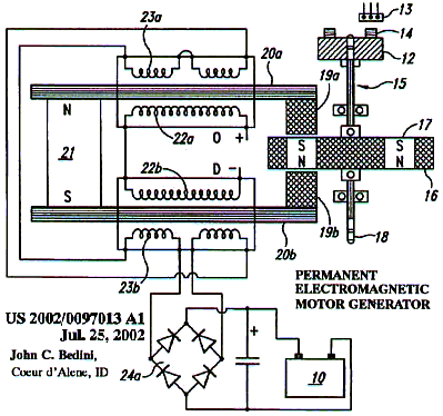
July 25, 2002 – Permanent Electromagnetic Motor Generator, John C.Bedini
Abstract: This invention is a back EMF permanent electromagnetic motor generator and method using a regauging process for capturing available electromagnetic energy in the system. The device is comprised of a rotor with magnets of the same polarity; a timing wheel in apposition to a magnetic Hall Effect pickup switch semiconductor; and a stator comprised of two bars connected by a permanent magnet with magnetized pole pieces at one end of each bar. There are input and output coils created by wrapping each bar with a conducting material such as copper wire. Energy from the output coils is transferred to a recovery rectifier or diode. The magnets of the rotor, which is located on a shaft along with the timing wheel, are in apposition to the magnetized pole pieces of the two bars. The invention works through a process of regauging, that is, the flux fields created by the coils is collapsed because of a reversal of the magnetic field in the magnetized pole pieces thus allowing the capture of available back EMF energy. Additional available energy may be captured and used to re-energize the battery, and/or sent in another direction to be used as work. As an alternative, the available back EMF energy may be dissipated into the system.
Claims: What is claimed is:
1. A back EMF permanent electromagnetic motor generator using a regauging process for capturing available electromagnetic energy in the system comprising: a. a means for producing a source of input energy to said motor generator, said energy conducted through a power switch and a magnetic timing switch; b. a means for timing said motor generator, said timing means a timing wheel connected to a shaft, said timing wheel comprised of one or more magnets, said magnets arranged so that the South polarity faces outward and is in apposition with said timing switch; c. a rotor and a means for transferring a force on said shaft, said rotor containing magnets having the same polarity; d. a stator comprised of two bars made of a magnetic conductive means, said bars connected by a permanent magnet and having a pole piece at one end of each said bar, said pole pieces thereby magnetized and in apposition with magnets of said rotor, said rotor positioned between said pole pieces; e. an input coil comprised of a conductive material wrapped around each of said bars of said stator, said input coil connected the electronic circuitry; f. an output coil comprised of a conductive material wrapped around each of said input coil of said bars, said output coils connected to a recovery rectifier or diode; g. a circuit for transferring electrical power, said circuit connecting said battery to said power switch, said circuit comprising a magnetic pickup timing switch thereby providing an electronic voltage pulse to said circuit and then to said magnetic coils resulting in rotation of said rotor, said rotor turning said timing wheel to provide additional electronic voltage pulses to said circuit and then to said coils again, thereby providing a means for collecting available back EMF energy for storage, use or dissipation into the system.
2. The motor generator of claim 1, wherein said input energy means is a battery.
3. The motor generator of claim 1, wherein said magnetic pickup timing switch is a Hall Effect magnetic pickup semiconductor.
4. The motor generator of claim 1, wherein the number of rotors may range from 1 to 60.
5. The motor generator of claim 1, wherein the number of magnets in said rotor has a range of 2 to 60.
6. The motor generator of claim 1, wherein said means for bar magnetic conduction may be ferrous, powdered iron, silicon steel, stainless magnetic steel, laminations of a conductive material or any other magnetic conductive material.
7. The motor generator of claim 1, wherein the number of magnetic conductive bars has a range of 2 to 120.
8. The motor generator of claim 1, wherein said means for transferring a force from said shaft may be a power take-off mechanism, gears, flywheels, belts or other methods of transferring force for the purpose of doing work.
9. A back EMF permanent electromagnetic motor generator using a regauging process for capturing available electromagnetic energy in the system comprising: a. a battery connected to a power switch and a Hall Effect magnetic pickup switch semiconductor, said magnetic pickup switch in apposition with a timing wheel, said timing wheel on a shaft; b. a rotor and a power take-off means on said shaft, said rotor having four magnets of the same polarity, said magnets equidistant from each other; c. a stator, said stator comprised of two iron bars connected by a permanent magnet and wrapped in a first copper conducting material to form an input coil that is connected to the electronic circuitry, said input coil wrapped in a second copper conducting material to form an output coil with said output coil connected to a recovery rectifier or single diode, said iron bars further having a pole piece at one of each end of said bars, said pole pieces in apposition to said magnets on said rotor; d. a circuit for transferring electrical power, said circuit connecting said battery to said power switch, said circuit comprising said Hall Effect magnetic pickup switch thereby providing an electronic voltage pulse through said circuit and then to said magnetic coils resulting in rotation of said rotor, said rotor turning said timing wheel to provide additional electronic voltage pulses to said coils again, thereby providing a means for collecting available back EMF energy for storage, use or dissipation into the system.
10. A method of producing a back EMF permanent electromagnetic motor generator using a regauging process comprising the steps of: a. placing a rotor containing magnets of the same polarity on a shaft with a timing wheel on said shaft; b. placing in apposition to said timing wheel a Hall Effect magnetic pickup switch semiconductor; c. placing in apposition to said magnets of said rotor magnetized pole pieces of a stator, said stator comprised of two conducting bars connected by a permanent magnet; d. wrapping said bars with a first conducting material to form an input coil, said input coil connected the electronic circuitry; f. wrapping said input coil with a seconding conducting material to form an output coil, said output coil connected to a recovery rectifier or a single diode; g. connecting a circuit for transferring electrical power, said circuit connected to a battery and a power switch, said circuit comprising a Hall Effect magnetic pickup switch thereby providing an electronic voltage pulse to said circuit and then to said magnetic coils resulting in increase rotation of said rotor, said rotor turning said timing wheel to provide additional electronic pulses to said circuit and then to said coils again, thereby providing a means for collecting available back EMF energy for storage, use or dissipation into the system.
2003, USP 0117111 A1
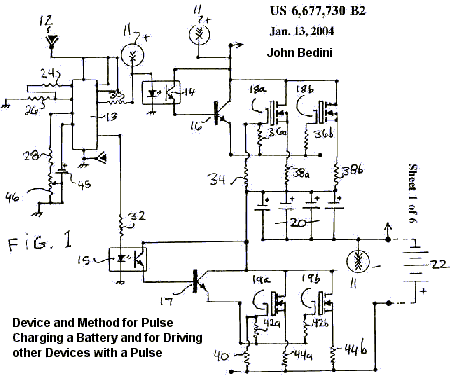
Jun. 26 2003, Device and Method for Pulse Charging a Battery and for Driving other Devices with a Pulse,
By John C. Bedini, Coeur d’Alene, ID (US).
– See more details on this patent on the dedicated page: zpe_bedini_solid.html
Abstract: A two-phase solid-state battery charger can receive input energy from a variety of sources including AC current, a battery, a DC generator, a DC-to-DC inverter, solar cells or any other compatible source of input energy.
Phase I is the charge phase and phase II the discharge phase wherein a signal or current passes through a dual timing switch that controls independently two channels dividing the two phases.
The dual timing switch is controlled by a logic chip or pulse width modulator. A potential charge is allowed to build up in a capacitor bank, the capacitor bank is then disconnected from the energy input source and then pulse charged at high voltage into the battery to receive the charge.
The momentary disconnection of the capacitor from the input energy source allows for a free-floating potential charge in the capacitor. Once the capacitor has completed discharging the potential charge into the battery, the capacitor disconnects from the battery and re-connects to the energy source thus completing the two-phase cycle.
