### Gray, Edward Vincent: his Patents (page created August 2007, updated November 2007)
## UKP GB2030801 A, Regenerative Energy Recovery System e.g. for electromagnetic propulsion, filled 21 Aug 1978, inventor Edwin Vincent Gray, file ‘GB2030801A.pdf’ from yahoogroup ‘alfenergy’
# Documents cited : GB 1358942 – GB 1358941 – GB 1309661 – GB 1302102 – GB 1228410 – GB 999978
# Field of search: H2F – H2J
# Applicant: Zetex Limited. Box 61, Grand Cayman, Cayman Islands, BWI
# Abstract: Back e.m.f. can result in energy loss, or inefficient use of energy, in inductive circuits. A regenerative energy recovery system embodying the present invention employs switching 6 to discharge a capacitor 3, through an inductive load 5, e.g. a motor.
When capacitor 3 is discharged, a diode 4 creates an alternative circuit path through which inductively maintained current may then continue to flow, for example to charge a battery 7.
The invention may be of particular value in electromagnetic propulsion systems.
# Specification: Regenerative energy recovery system
Backfround of the invention: The inventor believes this to be a unique and novel approach to the control of electrical energy for possible future application for the propulsion of inductive devices.
Through the use of certain inductive devices which enables the device to hold for a short period of time discharges of the capacitors to an external inductive load. The back EMF produced is captured and stored for future use. The result, then being, that the inventor believes this to be a more efficient use of energy.
Summary of the invention: The invention relates to ‘The Regenerative Energy Recovery System’ designed into a configuration wherein energy is momentarily stored for subsequent release for use in propelling electromagnetic devices.
The ‘Regenerative Energy Recovery System’ is designed to accept a high potential charge from a capacitor which has been charged from a high voltage power source. When the magnitude has been attained at a high level, this will cause a high current spike which can then be utilized into the inductive load. A part of the EMF, that is lost normally, is re-captured and re-routed and stored for future use.
According to the preferred embodiment of this invention is an energy conseving system. Examplary embodiments of the invention are herein illustrated. These examplary illustrations and descriptions should not be construed as limiting the invention to the embodiments shown, because those skilled in the arts appertaining to the invention may conceive of other embodiments in the light of the description.
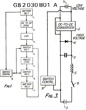
Description of the preferred embodiment: As herein mentioned, the basic principle of the regenerative energy recovery system, will be explained using the simplified block diagrams of FIG.1 and FIG.2.
Figure 1 shows all the major and necessary components in simplified block form.
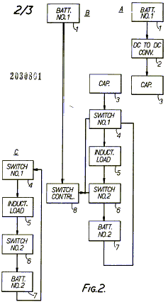
Figure 2 duplicates FIG.1 but is broken into three (3) sections A, B, C, corresponding to the three phases of operation of the process which takes place sequentially. The explanation will use FIG.2, but also applies to FIG.1.
Figure 3 shows an electrical schematic view of the system of FIGs.1 and 2.
Brief description of drawings: During phase A a capacitor (item 3) is charged to a high voltage of about 2,000 Volts. Battery No.1 shown as 24V (item 1) has its voltage charged to 2,000 V by the use of DC to DC converter (item 2). Item 1 is shown as a battery because that is usually a portable electrical energy source. Item 2 is any means suitable to change a low voltage to a high voltage. The phase A purpose is to obtained a high voltage charge in a suitable capacitor.
During phase B the capacitor (item 3) charged to a high voltage is discharged by closing the normally open (N.O.) switch (item 6). The switch control (item 8) programs when the switches (item 4 and 6) are operated. The discharge current is rapidly passed through switch number 1 (item 4), through the inductive load (item 5) and through the now closed switch number 2 (item 6), and through the energy recovery battery number 2 (item 7). Phase B continues until the capacitor approaches zero voltage whereupon the inertia of the current in the inductance of the inductive load would normally start an overshoot on reserved charge into the capacitor.
During phase C, the switch number 1 (item 4) disconnects capacitor (item 3) without interrupting the current flowing in the path described in phase B. That is, the current path is through items 5, 6, 7 and back through item 4 into the inductive load (item 5) in a closed loop.
Switches, items 4 and 6 are any devices which will perform the desired switching function in the corresponding parts of the circuit.
Inductive loads (item 5) may be a single load, or multiple loads. If a single load, the circuit may be duplicated so two inductive loads can interact in an inductive configuration.
If a single load, a permanent magnetic field may also be used so two interacting magnetic fields can cause force and motion. If multiple loads, one may be designated a rotor load. Suitable polarities will determine whether attractive or repulsive interaction will occur. The timing of the discharge will occur at the instant the loads are properly positioned. The timing of discharge will be determined by the switch control.
Claims:
1. A regenerative energy recovery system substantially as hereinbefore described with reference to FIGs.1 and 2 of the accompanying drawings.
2. A regenerative energy recovery system substantially as hereinbefore described with reference to FIG.3 of the accompanying drawings.
Printed for her Majesty’s Stationary Office by Burgess & Son (Abingdon) Ltd – 1980.
Published at The Patent Office, London.
## Edward V. Gray: Electro-Magnetic Association (EMA) Motor http://www.rexresearch.com/evgray/1gray.htm
## US Patent # 3,890,548 ; Pulsed Capacitor Discharge Electric Engine ; Edwin V. Gray
Abstract:
There is disclosed herein an electric machine or engine in which a rotor cage having an array of electromagnets is rotatable in an array of electromagnets, or fixed electromagnets are juxtaposed against movable ones. The coils of the electromagnets are connect3ed in the discharge path of capacitors charged to relatively high voltage and discharged through the electromagnetic coils when selected rotor and stator elements are in alignment, or when the fixed electromagnets and movable electromagnets are juxtaposed. The discharge occurs across spark gaps disclosed in alignment with respect to the desired juxtaposition of the selected movable and stationary electromagnets. The capacitor discharges occur simultaneously through juxtaposition of the selected movable electromagnets wound so that their cores are in magnetic repulsion polarity, thus resulting in the forced motion of movable electromagnetic elements away from the juxtaposed stationary electromagnetic elements at the discharge, thereby achieving motion. In an engine, the discharges occur successively across selected ones of the gaps to maintain continuous rotation. Capacitors are recharged between successive alignment positions of particular rotor and stator electromagnets of the engine.
Background of the Invention:
1. Field of the Invention:
There is no known engine or motor operated on the principle of the present invention, that a capacitor charged to a relatively high voltage from a low-voltage DC source is discharged across a spark gap to provided current through motor drive coils in the discharge path, these being solenoids which generate motion by magnetic repulsion of juxtaposed pairs of cores. The solenoids are preferably configured in motor and stator assemblies to effect motion of the rotor element with respect to the stator.
The present invention utilizes this principle to provide a rotary motion machine or engine which can develop considerable torque through the magnetic repulsion action of rotor and stator cores wound with coils through which capacitors are discharged synchronously with the positioning of the rotor coils opposite particular stator coils. Similarly, a linear action can be achieved with a stationary electromagnet juxtaposed against a movable electromagnet and the movable electromagnet can perform work with a tool or piston attached thereto.
A novel control mechanism is associated with the rotor is the engine to position discharge elements appropriately to create the desired discharge through the electromagnet coils when the juxtaposed rotor and stator electromagnets are in alignment. The electromagnets in the stator and rotor are so arranged that the control mechanism can advance or retard the discharge points relative to rotor-stator positions for control of rotational speed.
The discharge overshoot or back emf from the collapsing fields in the coils from the capacitor discharge is used to energize external batteries for conservation of power. The recovered energy thus stored may be used to operate equipment associated with the engine or motive force-producing device.
The engine or rotary electric machine of the invention is believed to operate on the principle of conservation of energy, in that once rotation is achieved, current is needed only a the instant of a capacitor discharge in order to advance the rotor. The rotor moves to the next discharge point on the inertia of the repulsion action. The capacitor is recharged during the interval and stores the energy until the discharge at the next rotor-stator coil coincidence. Thus, the new engine produces torque and stores the excess energy for subsequent use.
In a linear motion device according to the invention, only a single pulse discharge is needed to perform work.
The applications of the engine include use as an electric automotive engine which is economical and which can regenerate a part of the energy consumed to provide power for other loads in the automotive electric vehicle. As a linear actuator an economical use of power is possible because each stroke will result from a single discharge pulse of a capacitor through a coil.
2. Prior Art:
An extensive prior art search by the applicant uncovered no capacitor-discharge operated motor resembling that of the present invention. All motors of the patents located in the search employed direct electrical connection between coils and electric power sources. When selective switching is involved, semiconductor devices are employed, such as silicon-controlled rectifiers. Capacitors are used only for starting and phasing purposes, and not for basic motor operation from the discharge thereof, as in this invention.
# Summary of the Invention:
This invention relates to electric motors or engines, and more particularly to a new electric machine including electromagnetic poles in a stator configuration wherein in one form thereof the rotor is rotatable within the stator configuration and where both are energized by capacitor discharges through rotor and stator electromagnets at the instant of the alignment of a rotor electromagnet with a stator electromagnet. The rotor electromagnet is repelled from the stator electromagnet by the discharge of the capacitor through the coils of both the stator and rotor electromagnets at the same instant.
In an exemplary rotary engine according to this invention, rotor electromagnets may be disposed 120 degrees apart on a central shaft and major stator electromagnets may be disposed 40 degrees apart in the rotor housing about the stator periphery. Other combinations of rotor elements and stator elements may be utilized to increase torque or rotation rate.
In another form, a second electromagnet is positioned to one side of each of the major stator electromagnets on a center line 13-1/2 degrees from the center line of the stator magnet, and these are excited in a predetermined pattern or sequence. Similarly to one side of each major rotor electromagnet is a second electromagnet spaced on a 13-1/2 degree center line from the major rotor electromagnet. Electromagnets in both the rotor and stator assemblies are identical, the individual electromagnets of each being aligned axially and the coils of each being wired so that each rotor electromagnetic pole will have the same magnetic polarity as the electromagnet in the stator with which it is aligned and which it is confronting at the time of discharge of the capacitor.
Charging of the discharge capacitor or capacitors is accomplished by an electrical switching circuit wherein electrical energy from a battery or other source of DC potential may be applied in alternating polarity to ignition coils or other voltage step-up arrangements from which a high voltage DC potential is derived through rectification by diodes.
The capacitor charging circuit comprises a pair of high frequency switches which feed respective automotive-type ignition coils employed as step-up transformers. The “secondary” of each of the ignition coils provides a high-voltage square wave to a half-wave rectifier to generate a high voltage output pulse of DC energy with each switching alternation of the high frequency switcher. Only one polarity is used so that a unidirectional pulse is applied to the capacitor bank being charged.
Successive unidirectional pulses are accumulated on the capacitor or capacitor bank until discharged. Discharge of the bank of capacitors occurs across a spark gap by arc-over. The gap spacing determines the voltage at which discharge or arc-over occurs. An array of gaps is created by fixed elements in the engine housing and moving elements positioned on the rotor shaft. At the instant when the moving gap elements are positioned opposite fixed elements during the rotor rotation, a discharge occurs through the coils of the aligned rotor and stator electromagnets to produce the repulsion action between the stator and rotor electromagnet cores.
A plurality of fixed gap elements are arrayed in the motor housing to correspond to the locations of the stator electromagnets in the housing. The rotor gap elements correspond to the positions of the rotor electromagnets on the rotor so that at the instant of correct alignment of the gaps the capacitors are discharged to produce the necessary current through the stator and rotor coils to cause the electromagnets to repel one another.
The charging circuits are arranged in pairs, and are such that the discharge occurs through both rotor and stator windings of the electromagnets, which are opposite one another when the spark gap elements are aligned and arc-over.
The speed of the rotor can be changed by means of a clutch mechanism associated with the rotor. The clutch shifts the positions of the rotor gap elements to that the discharge will energize the stator coils in a manner to advance or retard the time of discharge with respect to the normal rotor/stator alignment positions. The discharge through the rotor and stator then occurs when the rotor has passed the stator 6-2/3 degrees for speed advance.
By causing the discharge to occur when the rotor position is approaching the stator, the repulsion pulse occurs 6-2/3 degrees before the alignment position of the rotor and stator electromagnets, thus slowing the speed.
The clutch mechanism for aligning capacitor discharge gaps for discharge is described as a control head. It may be likened to a firing control mechanism in an automobile combustion engine in that it “fires” the electromagnets and provides a return of any discharge overshoot potential back to the battery or other energy source.
The action of the control head is extremely fast. From the foregoing description, it can be anticipated that an increase in the speed or a decrease in speed of rotation can occur within the period in which the rotor electromagnet moves between any pair of adjacently located electromagnets in the stator assembly, which are 40 degrees apart in the exemplary engine according to the invention. Thus, speed changes can be effected in a maximum of one-ninth of a revolution.
The rotor speed-changing action of the control head and its structure are believed to be further novel features of the invention, in that they maintain normal 120 degree firing positions during uniform speed or rotation conditions, but shift to + 6-2/3 degrees longer or shorter intervals for speed change by the novel shift mechanism in the rotor clutch assembly.
Accordingly, the preferred embodiment of this invention is an electric rotary engine wherein motor torque is developed by discharge of high potential from a bank of capacitors through stator and rotor electromagnet coils when the electromagnets are in alignment. The capacitors are charged from batteries by a switching mechanism, and are discharged across spark gaps set to achieve the discharge of the capacitor charge voltage through the electromagnetic coils when the gaps and predetermined rotor and stator electromagnet pairs are in alignment.
Exemplary embodiments of the invention are herein illustrated and described. These exemplary illustrations and description should not be construed as limiting the invention to the embodiments shown, because those skilled in the arts pertaining to the invention may conceive of other embodiments in the light of the description within the ambit of the appended claims.
# Brief Description of the Drawings:
Figure 1 is an explanatory schematic diagram of a capacitor charging and discharging circuit utilized in the present invention;
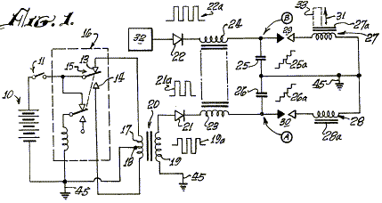
Figure 2 is a block diagram of an exemplary engine system according to the invention;
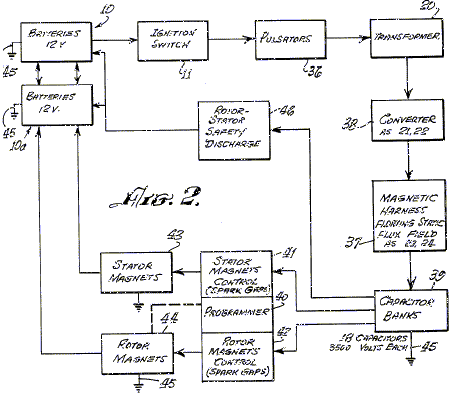
Figure 3 is a perspective view of a typical engine system according to the invention, coupled to an automotive transmission;
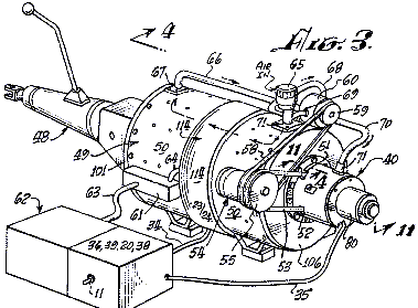
Figure 4 is an axial sectional view taken at line 4-4 in Figure 3;
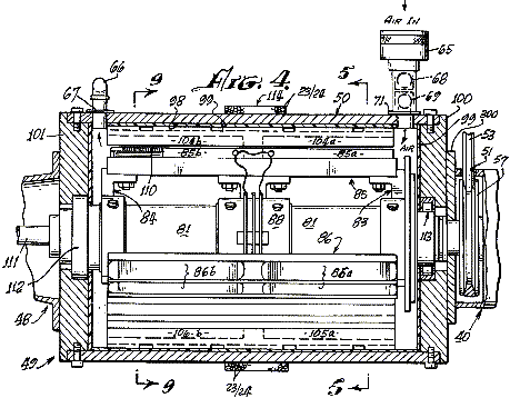
Figure 5 is a sectional view taken at line 5-5 in Figure 4;
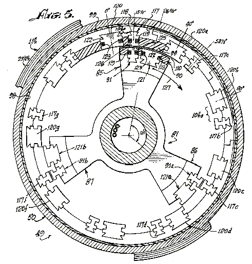
Figure 6 and Figure 7 are fragmentary sectional views, corresponding to a portion of Figure 5, illustrating successive advanced positions of the engine rotor therein;
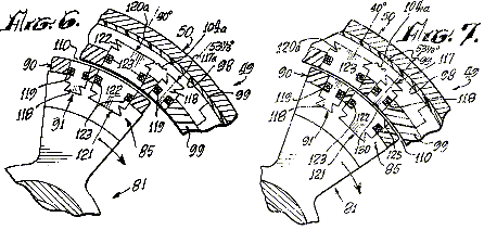
Figure 8 is an exploded perspective view of the rotor and stator of the engine of Figures 3 and 4;
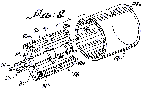
Figure 9 is a cross-sectional view taken at line 9-9 of Figure 4;
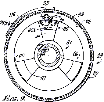
Figure 10 is a partial sectional view, similar to the view of Figure 9, illustrating a different configuration of electromagnets in another engine embodiment of the invention;
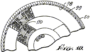
Figure 11 is a sectional view taken at line 11-11 in Figure 3, illustrating the control head or novel speed change controlling system of the engine;
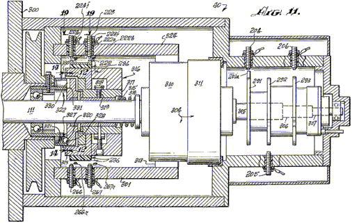
Figure 12 is a sectional view, taken at line 12-12 in Figure 11, showing a clutch plate utilized in the speed control system of Figure 11;
Figure 13 is a fragmentary view, taken at line 13-13 in Figure 12;
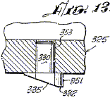
Figure 14 is a sectional view, taken at line 14-14 in Figure 11, showing a clutch plate which operates with the clutch plate of Figure 12;
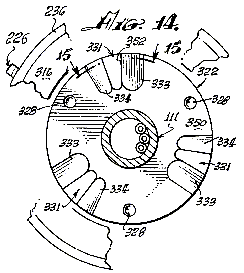
Figure 15 is a fragmentary sectional view taken at line 15-15 of Figure 13;
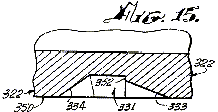
Figure 16 is a perspective view of electromagnets utilized in the present invention;
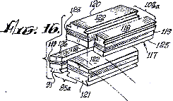
Figure 17 is a schematic diagram showing cooperating mechanical and electrical features of the programmer portion of the invention;
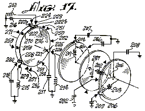
Figure 18 is an electrical schematic diagram of an engine according to the invention, showing the electrical relationships of the electromagnetic components embodying a new principle of the invention; and
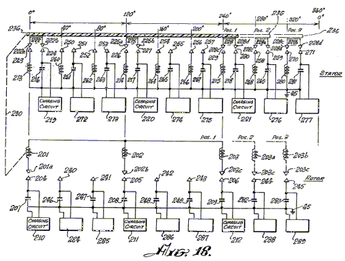
Figure 19 is a developed view, taken at line 191-19 of Figure 11, showing the locations of displaced spark gap elements of the speed changing mechanism of an engine according to the invention.
# Description of the Preferred Embodiment:
As hereinbefore mentioned, the basic principle of operation of the engine of the invention is the discharge of a capacitor, across a spark gap through an inductor. When a pair of inductors is used, and the respective magnetic cores thereof are arranged opposite and another in magnetic polarity repulsion relation, the discharge through them causes the cores to repel each other with considerable force.
Referring to the electrical schematic diagram of Figure 1, a battery 10 energizes a pulse-producing vibrator mechanism 16, which may be of the magnetic type incorporating an armature 15 moving between contacts 13 and 14, or of the transistor type (not shown) with which a high frequency bipolar pulsed output is produced in primary 17 of transformer 20. The pulse amplitude is stepped up in secondary 19 of transformer 20. Wave form 19a represents the bi-directional or bipolar pulsed output. A diode rectifier 21 produces a unidirectional pulse train, as indicated at 21a, to charge capacitor 26. A delay coil 23 is connected in series with the unipolar pulsed output to capacitor 26. Successive unidirectional pulses of wave 21a charge capacitor 26 to a high level, as indicated at 26a, until the voltage amplitude at point A reaches the breakdown potential of spark gap 30. At the breakdown of spark gap 30, capacitor 26 discharges across the arc created through the inductor coil 28. A current pulse is produced which magnetizes core 28a. Simultaneously, another substantially identical charging system 32 produces a discharge through inductor 27 across spark gap 29 to magnetize core 27a. Cores 28s, 27a are wound with coils 28, 27 so that their magnetic polarities are the same. As the cores 27a, 28a confront one another, they tend to fly apart when the discharge occurs through coils 27 and 28 because of repulsion of identical magnetic poles, as indicated by arrow 31. If core 28a is fixed or stationary and core 27a is movable, then core 27a may have tools 33 attached to it to perform work when the capacitor discharges.
Referring to Figures 1 and 2, a DC electrical source or battery 10 energizes pulsators 36 (including at least two vibrators 16 as previously described) when switch 11 between the battery 10 and pulsator 36 is closed, to apply relatively high frequency pulses to the primaries of transformers 20. The secondaries of transformers 20 are step-up windings which apply bipolar pulses, such as pulses 19a (Figure 1) to the diodes in converter 38. The rectified unidirectional pulsating output of each of the diodes in converter 38 is passed through delay coils 23, 24, thus forming a harness 37 wound about the case of the engine, as hereinafter described, which is believed to provide a static floating flux field. The outputs from delay lines 37 drive respective capacitors in banks 39 to charge the capacitors therein to a relatively high charge potential. A programmer and rotor and stator magnet control array 40, 41, 42 is formed by spark gaps positioned, as hereinafter described, so that at predetermined positions of the rotor during rotation of the engine, as hereinafter described, selected capacitors of capacitor banks 39 will discharge across the spark gaps through the rotor and stator electromagnets 43, 44. The converters 38, magnetic harness 37, capacitor banks 39, programmer 40, and controls 41, 42 form a series circuit path across the secondaries of transformer 20 to the ground, or point of reference potential, 45. The capacitor banks 39 are discharged across the spark gaps of programmer 40 (the rotor and stator magnet controls 41, 42). The discharge occurs through the coils of stator and rotor electromagnets 43, 44 to ground 45. Stator and rotor electromagnets are similar to those shown at 27, 27a, 28, 28a in Figure 1.
The discharge through the coils of stator and rotor electromagnets 43, 44 is accompanied by a discharge overshoot or return pulse, the output of which is applied in an appropriate polarity to a secondary battery 10a to store this excess energy. The overshoot pulse returns to battery 10a because after discharge the only path open is that to battery 10a, since the gaps in 40, 41, and 42 have broken down, because the capacitors in banks 39 are discharged and have not yet recovered the high voltage charge from the high frequency pulsers 36 and converter rectifier units 38.
In the event of a misfire in the programmer control circuits 40, 41, 42,the capacitors are discharged through a rotor safety discharge circuit 46 and returned to batteries 10-10a, adding to their capacity. The circuit 46 is connected between the capacitor banks 39 and batteries 10, 10a.
Referring to Figure 3, a motor or engine 49 according to the present invention is shown connected with the automotive transmission 48. The transmission 48 represents one of many forms of loads to which the engine may be applied. A motor housing 50 encase the operating mechanism hereinafter described. The programmer 40 is axially mounted at one end of this housing. Through aperr4es 51, 52, a belt 53 couples to a pulley 57 (not shown in this view) and to an alternator 54 attached to housing 50. A pulley 55 on the alternator has two grooves, one for belt 53 to the drive pulley, and the other for a belt 58 coupled to a pulley 59 on a pump 60 attached to housing 50. A terminal box 61 on the housing interconnects means between the battery assembly 62 and motor 49 via cables 63 and 64.
An intake 65 for air is coupled to pump 60 via piping 68, 69 and from pump 60 via tubing or piping 66, 70 to the interior of housing 50 via coupling flanges 67 and 71. The air flow tends to cool the engine, and the air may preferably be maintained at a constant temperature and humidity so that a constant spark gap discharge condition is maintained. A clutch mechanism 80 is provided on programmer 40.
Referring to Figures 4, 5, and 9, rotor 81 has spider assemblies 83, 84 with three electromagnet coil assembly sets mounted thereon, two of which are shown in Figure 4, on 85 at 85a and 85b, and on 86 at 86a and 86b. One of the third electromagnet coil assemblies, designated 871, is shown in Figure 5, viewed from the shaft end. As more clearly shown in the perspective view of Figure 8, a third spider assembly 88 provides added rigidity and a central support for the rotor mechanism on shaft 81.
The electromagnet sets 85a and 85b, 86a and 86b, 87a and 87b, disposed on rotor 81 and spiders 83, 84, and 88 each comprise pairs of front units 85a, 86a, 87a and pairs of rear units 85b, 86b, 87b. Each pair consists of a major electromagnet and a minor electromagnet, as hereinafter described, which are embedded in an insulating material 90, which insulates the electromagnet coil assemblies from one another and secures the electromagnets rigidly in place on the spider/rotor cage 81, 83, 84, 88.
The interior wall 98 of housing 50 I coated with an electrically insulating material 99 in which are embedded electromagnet coils, as hereinafter described, and the interiors of end plates 100, 01, of the housing 50. On the insulating surface 98 of housing 50 is mounted a series of stator electromagnet pairs 104a, identical with electromagnet pairs 85a, 86a, 87a, etc. Electromagnet pairs such as 104a and 105a are disposed every 40 degrees about the interior of housing 50 to form a stator which cooperates with the rotor 81-88. An air gap 110 of very close tolerance is defined between the rotor and stator electromagnets, and air from pump 65 flows through this gap.
As shown in Figure 8, the electromagnet assemblies, such as 85 through 87, of the rotor and magnet assemblies, such as 104a in the stator are so embedded in their respective insulative plastic carriers (rotor and stator) that they are smoothly rounded in a concave contour for the stator, and in a convex contour on the rotor to permit smooth and continuous rotation of rotor 81 in stator housing 50. The air gap 110 is uniform at all positions of any rotor element within the stator assembly, as is clearly shown in Figure 16.
The rotor 81 and spiders 83, 84, 88 are rigidly mounted on a shaft 111 journaled in bearing assemblies 12, 113 which are of conventional type, for easy rotation of the rotor on shaft 111 within housing 50.
Around the central outer surface of housing 50 are wound a number of turns of wire 23, 24 to provide a static flux coil 114 as hereinbefore described, which is a delay line, as previously described.
Figures 5, 6, 7 and 9 are cross-sectional views of the rotor assembly 81-88, arranged to show the positioning and alignment of the rotor and stator assemblies at successive stages of the rotation of rotor 81-88 through a portion of a cycle of operation thereof. For example, I Figure 5 the rotor assembly 81-88 is shown so positioned that a minor stator electromagnet assembly 91 is aligned with a minor electromagnet assembly 117.
As shown in further detail in Figure 16, minor electromagnet assembly 117 consists of an iron core 118, grooved so that there may be wound thereabout a coil of wire 119. Core 118 is the same in stator electromagnet 117 as it is in rotor electromagnet 91.
At a position 13-1/2 degrees to the right of rotor electromagnet 91, as viewed in Figure 5, there is a second or major stator electromagnet 120 whose core 122 is of the same configuration as core 122 of rotor electromagnet 121. A winding 123 about core 122 of electromagnet 120 is of the same character as winding 123 on electromagnet 121.
Electromagnet assembly pair 85a on the rotor is identical in configuration with that of the electromagnet stator assembly pair 104a except for the position reversal of the elements 117-120 and 91-121 of the respective pairs.
There are nine pairs of electromagnets 120-117 (104a) disposed at 40-degree intervals about the interior of housing 50. The center line of core 122 of electromagnet 120 is positioned 13-1/2 degrees to the left of the center line of the core 118 of electromagnet 117. Three pairs of electromagnets 85a, 86a, 87a, are provided on rotor assembly 81-88 as shown in Figure 5.
Other combinations are possible, but the number of electromagnets in the rotor should always be an integral fraction of the number of electromagnets in the stator. As shown in Figure 8, for the rotor assembly 85a, 85b, there are three of each of the front and back pairs of electromagnetic assemblies. Similarly, as shown in Figures 4 and 8, there are nine front and back pairs of electromagnets in the stator such as 104a and 104b.
In order to best understand the operation of the rotor 81-88 rotating within the stator housing 50 of an engine according to this invention, the positions of rotor electromagnets 91 and stator electromagnets 117 are initially exactly in line at the 13-1/2 degree peripheral starting position marked on the vertical center line of figure 5. The winding direction of the coils of these magnets is such that a DC current through the coils 119 will produce a particular identical magnetic polarity on each of the juxtaposed surfaces 125 of magnets 117 and 126 of magnet 91 (Figure 5). Figures 6 and 16 illustrate the next sep in motion wherein the two major electromagnets, 120 in the stator and 121 in the rotor, are in alignment.
When the DC-discharges from the appropriate capacitors in banks 39 occur simultaneously across spark gaps through the coils 119 of electromagnets 117 and 91, at the instant of their alignment, their cores 118 will repel one another to cause rotor assembly 81-88 to rotate clockwise in the direction indicated by arrow 127. The system does not move in the reverse direction because it has been started in the clockwise direction by the alternator motor 54 shown in Figure 3, or by some other starter means. If started counterclockwise, the rotor will continue to move counterclockwise.
As hereinbefore noted, the discharge of any capacitor occurs over a very short interval across its associated spark gap, and the resulting magnetic repulsion action imparts motion the rotor. The discharge event occurs when electromagnets 117 and 91 are in alignment. As shown in Figure 5, rotor electromagnet 91a is aligned with stator electromagnet 117c, and rotor electromagnet 91b is aligned with stator electromagnet 1173 at the same time that similar electromagnets 117 and 91 are aligned. A discharge occurs through all six of these electromagnets simultaneously (that is, 117, 91; 117c, 91a; 117e and 91b). A capacitor and a spark gap are required for each coil of each electromagnet. Where, as in the assembly shown in Figure 8, front and back pairs are used, both the axial in-line front and back coils are energized simultaneously by the discharge from a single capacitor or from a bank of paralleled capacitors such as 25, 26 (Figure 1). Although Figures 4 and 8 indicate the used of front and back electromagnets, it should be evident that only a single electromagnet in any stator position and a corresponding single electromagnet in the rotor position, may be utilized to accomplish the repulsion action of the rotor with respect to the stator. As stated, each electromagnet requires a discharge from a single capacitor or capacitor bank across a spark gap for it to be energized, and the magnetic polarity of the juxtaposed magnetic core faces must be the same, in order to effect the repulsive action to produce the rotary motion.
Referring to Figures 5 and 6, the repulsion action causes the rotor to move 13-1/3 degrees clockwise, while electromagnets 91, 91a and 91b move away from the electromagnets 117, 117c and 117e to bring electromagnets 121, 121a and 121b into respective alignment with electromagnets 120a, 120d and 120f. At this time, a capacitor discharge across a spark-gap into their coils 123 occurs, thus moving the rotor. Another 13-1/3 degree ahead, as shown in Figure 7, major electromagnets 121, 121a and 121b come into alignment with minor electromagnets 117a, 117d and 117f, at which time a discharge occurs to repeat the repulsion action, this action continuing as long as DC power is applied to the system to charge the capacitors in the capacitor banks.
Figure 18 further illustrates the sequencing of the capacitor discharges across appropriate spark gap terminal pairs. Nine single stator coils and three single rotor coils are shown with their respective interconnections with the spark gaps and capacitors with which they are associated for discharge. When the appropriate spark gap terminals are aligned, at the points in the positioning of the rotor assembly for most effective repulsion action of juxtaposed electromagnet cores, the discharge of the appropriate charged capacitors across the associated spark gap occurs through the respective coils. The capacitors are discharged in sets of three through sets of three coils at each discharge position, as the rotor moves through the rotor positions. In Figure 18, the rotor electromagnets are positioned linearly, rather than on a circular base, to show the electrical action of an electric engine according to the invention. These motor electromagnets 201, 202, and 203 are aligned with stator electromagnets 213, 214, and 215 at 0 degrees, 120 degrees and 450 degrees respectively. The stator electromagnets are correspondingly shown in a linear schematic as if rolled out of the stator assembly and laid side by side. For clarity of description, the capacitors associated with the rotor operation 207, 208, 209 and 246, 247, 248, 249, 282 ad 283 are arranged in vertical alignment with the respective positions of the rotor coils 201, 202, 203 as they move from left to right, this corresponding to clockwise rotation of the rotor. The stator coils 213, 214, 215, 260, 261, 262, 263, 264, 265, 266, etc., and capacitor combinations are arranged side by side, again to facilitate description.
An insulative disc 236 (shown in Figure 17 as a disc, but opened out linearly in Figure 18) has mounted thereon three gap terminal blocks 222, 225 and 228. Each block is rectangularly U-shaped, and each interconnects two terminals with the base of the U. Block 222 has terminals 222a and 222b, block 225 has terminals 225a and 225b, block 228 has terminals 228c and 228d. When insulative disc 230 is part of the rotor, as indicated by mechanical linkage 290, it can be seen that terminal U 222 creates a pair of gaps with gap terminals 223 and 224, respectively. The stator electromagnets are correspondingly shown in linear schematic as if rolled out of the stator assembly and laid side by side. For clarity of description, the capacitors associated with the rotor operation 207, 208, 209, and 246, 247, 248, 249, 282 and 283 are arranged in vertical alignment with the respective positions of the rotor coils 201, 202, 203 as they move from left to right, this corresponding to clockwise rotation of the motor. The stator coils 213, 214, 215, 260, 261, 262, 263, 264, 265, 266, etc., and capacitor combinations are arranged side by side, again to facilitate description.
An insulative disc 236 (shown in Figure 17 as a disc, but opened out linearly in Figure 18) has mounted thereon three gap terminal blocks 222, 225, and 228. Each block is rectangularly U-shaped, and each interconnects two terminals with the base of the U. Block 222 ha terminals 222a and 222b, block 225 has terminals 225a and 225b, and block 228 has terminals 228c and 228d. When insulative disc 230 is part of the rotor, as indicated by mechanical linkage 290, it can be seen that terminal U 222 creates a pair of gaps with terminals 223 and 224, respectively. Thus, when the voltage on capacitor 216 from charging circuit 219 is of a value which will arc over the air spaces between 222a and 223, and between 222b and 224, the capacitor 216 will discharge into the coil of electromagnet 213 to ground. Similarly gap terminal U 225 forms a dual spark gap with terminals 226 and 227 to result in arc-over when the voltage on capacitor 217, charged by charging circuit 220, discharges into the coil of electromagnet 214. Also, U-gap terminal 228 with terminals 228c and 228d, creates a spark gap with terminals 229 and 230 to discharge capacitor 218, charged by charging circuit 221, into coil 215. At the same time, rotor coils 201, 202 and 203 across gaps 201a-204, 202b-205 and 203c-206 each receives a discharge from respective capacitors 207, 208 and 209.
When the electromagnet coils 213, 214, 215 an 201, 202, 203 are energized, the repulsion action causes the rotor assembly to move to position 2 where a new simultaneous group of discharges occurs into rotor coils 201, 202, and 203 from capacitors 246, 248, and 282 across gaps 201a-240, 202b-242 and 203c-244. Simultaneously, because gap U-elements 222, 225, and 228 have also moved to position 2 with the rotor assembly, capacitor 261 is discharged through electromagnet coil 260, capacitor 265 is discharged through electromagnet coil 264, and capacitor 269 is discharged through electromagnet coil 168 in alignment with position 2 of the rotor electromagnet coils, thus to cause the rotor electromagnets to move to position 3 where the discharge pattern is repeated now with capacitors 247, 249 and 283 discharging through the rotor electromagnet coils 201, 202, 203, and the capacitors 263, 267 and 281 discharging respectively through stator electromagnet coils 262, 266 and 280.
After each discharge the charging circuits 219-221 and 272-277 for the stator capacitors, and 210-212 and 284-289 for the rotor capacitors, are operated continuously from a battery source, as described earlier with reference to Figure 1, to constantly recharge the capacitors to which each is connected. Those versed in the art will appreciate that, as each capacitor discharges across an associated spark gap, the resulting drop in potential across the gap renders the gap an open circuit until such time as the capacitor can recharge to the arc-over level of the gap. This recharge to a discharge potential occurs before a rotor element arrives at the next position in question.
The mechanical schematic diagram of Figure 17 further clarifies the operation of the spark-gap discharge programming system. A forward disc 236 of an electrically insulative material, has thereon the set of U-shaped gap terminal connectors previously described. These are positioned at 0 degrees, 120 degrees and 240 degrees respectively. In Figure 17, schematic representations of the position of the coil and capacitor combinations at the start of a cycle are shown to correspond to the description hereinabove with reference to Figure 18. Accordingly, the coil and capacitor combinations 213/216, 214/217, and 215/218 are shown connected with their gap terminals, respectively, 223/224, 226/227, and 229/230. On the rotor coil and capacitor connection three separate discs 291, 292 and 293 are shown, each with a single gap terminal. The discs 291-293 are rotated so as to position their respective gap terminals 201a, 202b and 203c at 120 degree increments, with the 0 degree position corresponding to the 0 degree position of U-gap terminal 222 on disc 230.
Representative gap terminals are shown about the peripheries of discs 230, 291-193 to clearly indicate how, as the discs turn in unison, the gap alignments correspond so that three rotor coil/capacitors always line up at 120 degree intervals about the rotary path, producing an alignment every 40 degrees, there being nine stator coils. Thus there are three simultaneous discharges into stator coils and three into rotor coils at each 40 degree position. Nine positions displaced 40 degrees apart provide a total of 27 discharge points for capacitors into the stator coils in one revolution.
It will be understood that, as illustrated in Figures 17 and 18, nine individual electromagnet coils are shown in the stator and three in the rotor, in order to show in its simplest form how the three rotor electromagnets are stepped forward from the alignment with three of the stator electromagnets, when the appropriate spark gaps are in alignment, to effect the discharge of capacitors through juxtaposed pairs of rotor/stator electromagnets. The repulsion moves the rotor electromagnet from the stator electromagnet to the next alignment position advanced at an arc of 40 degrees from the preceding alignment position. In the interval until another rotor electromagnet, 120 degrees removed, is aligned with the stator electromagnet that has just been excited, the associated capacitor is recharged to a potential which will cause the spark gap to break down to produce another discharge of this capacitor on the next revolution. Thus the rotor moves from one position to the next, with capacitor discharges occurring each 40 degrees of rotation, a total of nine per revolution. It should be obvious that, with other rotor/stator combinations, the number of electromagnet coincidences and spark-gap discharges will vary. For example, with the coil pairs shown in Figures 4 through 8, a total of 27 discharges will occur. Although there are 18 stator electromagnets and three rotor electromagnets, the discharge pattern is determined by the specific spark gap arrangement.
The rotor/stator configuration of Figures 5 and 8, involving the major and minor pairs of electromagnets such as 85a and 104a (the terms “major” and “minor” referring to the difference in size of the elements), include nine pairs of electromagnets in the stator, such as 104a, with three electromagnet pairs of the rotor, such as 85a. Because of the 13-1/3 degree separation between the major and minor electromagnets in the rotor pair 85a, with the same separation of minor and major electromagnets of the stator pair 104a, the sequence of rotation and discharge described above, with respect to the illustrative example of Figure 5, involves the following:
(1) A minor element 117 of stator pair 104a is aligned with the minor element 91 of rotor pair 85a. On the discharge, this moves the rotor ahead 13-1/3 degrees.
(2) The major rotor element 122 of the pair 85a now is aligned with the major stator element 120b of the next electromagnet pair, in the stator array as shown in Figure 6. On the discharge, the rotor moves ahead 13-1/3 degrees.
(3) This brings the minor rotor electromagnet 91 into alignment with the major stator element 120 b of pair 104d, and the major electromagnet 122 (just discharged) of pair 85a into alignment with minor electromagnet 117b of pair 104d, and the rotor spark gap elements into alignment with a different position of gap elements connected with capacitors not discharged in the previous position of the rotor. It should be remembered at this point that it is the positioning of a rotatable spark gap array, similar to that illustrated in Figures 17 and 18, which controls the time of discharge of capacitors connected to these gap terminals. Therefore, any electromagnet can be energized twice successively from separate capacitors as the motor brings appropriate gap terminals into alignment with the coil terminals of a particular electromagnet.
Thus, although major electromagnet 120b of pair 104d has just been energized as described above, it can now be energized again along with minor rotor electromagnet 91 in step 3, because the rotor moved to a new set of terminals of the spark gap arrays connected with capacitors not yet discharged. These capacitors now discharge through rotor electromagnet 91 and stator electromagnet 120b, causing rotor to move ahead another 13-1/3 degrees, thus again aligning two minor electromagnets again, these being 117b of stator pair 104 d and 91 of rotor pair 85a. The rotor has now moved 40 degrees since step 1 above. The sequence is repeated, and it is to be noted that at each 13-1/3 degree step, the discharges rotate the rotor another 13-1/3 degrees. There are 27 steps per revolution with nine stator coil pairs. The discharge sequence is not uniform, as is shown in Table 1. In the stator, three major electromagnets 120 degrees apart are energized twice in sequence followed by a hiatus of one step while three minor electromagnets of the stator, 120 degrees apart, are energized during the hiatus. In the rotor the major electromagnets are energized during a hiatus step following two minor electromagnet energization steps. A total of 27 energizations are thus accomplished in the nine pairs of coils of the stator.
In Table 1, the leftmost column depicts the location of each rotor arm 85, 86, 87 at an arbitrarily selected step No. 1 position. For example, in step 1 rotor arm 85 has a minor stator and minor rotor electromagnet in alignment for capacitors to discharge through them simultaneously at the 13-1/3 degree position.
Table 1: Capacitor Discharge Sequence for One Revolution of Rotor in System of Figures 5 & 8
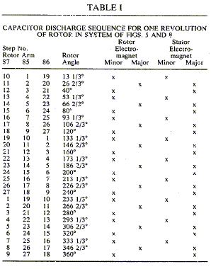
Similarly, in step 1 rotor arm 86 is at the 133-1/2 degree position with a minor rotor and minor stator electromagnet in alignment for discharge. Simultaneously, rotor arm 87 is at the 253-1/3 degree position with a minor rotor and minor stator in alignment for capacitor discharge therethrough. The other steps of the sequence are apparent from Table 1, for each position of the three rotor arms at any step and the juxtapositions of respective stator and rotor electromagnet elements at that position.
In the simplified motor arrangement shown in schematic form in Figure 18, with single electromagnet configuration the alignment is uniform and the discharge sequences follow sequentially.
As hereinafter mentioned, a change in speed is effected by displacing the stator spark gap terminals on the rotor (shown at 236 in Figures 17 and 18) either counter-clockwise or clockwise 6-2/3 degrees so that the discharge position of the stator electromagnets is displaced 6-2/3 degrees either clockwise or counter-clockwise of the rotor electromagnet at the time of discharge. Referring to Figures 11 to 15, the simultaneous discharge of selected capacitors into the electromagnets so displaced results in a deceleration at the time the rotor electromagnet is just approaching the associated stator, or an acceleration if the rotor electromagnet is just leaving its associated stator electromagnet. In each event, there is a repulsive reaction between the stator and rotor electromagnets, so that if the rotor is approaching the stator, there is a slow-down and if the rotor is receding from the stator there is a speed-up.
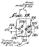
Referring to Figure 11, clutch mechanism 304 about shaft 111 is operated electromagnetically in conventional manner to displace the spark-gap mechanism 236 which is operated in appropriate matching alignment with the rotor spark-gap discs 291, 292, 293. Clutch 304 has a fixed drive element 311 containing an electromagnetic drive coil (not shown) and a motor element 310 which, when the electromagnetic drive coil is energized, can be operated by a direct current. The operation of motor element 310 brings into operation spark gap elements 224r, 223r or 223f, 224f of the system shown in Figures 4, 5, and 8, as illustrated in Figure 19.The fixed stator coil spark gap terminal pairs 223, 224 and 266, 267 are arrayed about a cylindrical frame 322 which is fabricated in insulative material. In the illustrative example of Figures 17 and 18, there are nine such spark gap terminal pairs about the periphery of cylinder frame 324. In the engine of Figures 4 to 8, a total of 27 such spark gap pairs are involved. In addition, although not shown in the drawing, there are also pairs of terminals, such as 223r or 223f, 224r or 224f and 266r or 226f, 267r or 267f, displaced 6-2/3 degrees on either side of the pairs 223, 224, or 266, 267, and all other pairs in the spark gap array, the letters r and f denoting “retard” and “faster’. The latter displaced pairs are used in the control of speed of the engine rotor. The displaced pairs not shown are involved with the operation of clutch 304, the speed changing control element.
Clutch 304 is associated with shaft 111 in that the movable element 10 draws clutch disc element on shaft 111 away form clutch disc element 322 when energized by a voltage of appropriate polarity applied to its motor electromagnet 311. Such clutch drives are well known in the art.
The clutch mechanism 304 of Figures 11 and 19, when not energized is in the configuration shown in Figure 11. The energized configuration of clutch 304 is not specifically illustrated. Upon energization, spark-gap element 222 on disc 236 is displaced rightward, as viewed in Figure 11, by broken lines 236x, into alignment with the positions of fixed spark-gap terminals 223f, 224f and 267r, 266r. When the disc is in position 236x, the flattened edge 332 of pin 330 in disc 325 rides on surface 350 of disc 322. Normally, the flattened edges 351 of pins 330 are engaged against the flat edge 352 in recess 331 of disc 322. The displacement of disc 322 on shaft 111 is effected by the action of clutch 304 against spring 314 (Figure 11). An electric switch (not shown) of clutch mechanism 304 energizes it from a DC power source, and has two positions, one for deceleration and one for acceleration. In either position, clutch 304 is engaged to pull clutch disc 322 from clutch disc 325, momentarily. For the decelerate or accelerate position, the displaced alignment of spark gap elements 222 is with the 224f, 223f and the 224r, 223r spark-gap terminal elements. However, only the 224f, 223f spark-gap elements are switched into operation with appropriate capacitors for the accelerate position, while in the decelerate position only the 223r and 224r spark-gap elements are switched into the circuit with their associated capacitors.
Of course, when insulative disc 236 is displaced by clutch 304, its gap terminals 22, 225 and 228 (Figures 14 and 18) are all displaced into the alignment position of 236x so as to engage the r and f lines of fixed spark gap elements. Although the accelerate and decelerate positions of disc 236 are the same, it is the switching into operation of the 223, 224 or 266, 267 exemplary r or f pairs of terminals which determine whether speed up or slow down action of the rotor will occur.
The momentary displacement of clutch disc 322 from clutch disc 325 results in rotation of disc 325 about disc 322 through an angle 0f 120 degrees. The detent ball and spring mechanism 320, 321 in disc 325 positions itself between open detent dimple 328 and a succeeding one 328 at a position 120 degrees away on disc 325. As stated, flat 332 of pin 330 rides on surface 350 of disc 322, and pin 330 leaves the pin-holding groove 331/352 along ramp 333 in disc 322 during the momentary lifting of disc 322 by clutch 304. Pin 330 falls back into the next groove 331 at point 120 degrees further on about disc 322. Pin 330 falls into place in groove 331 on ramp 334. Pins 330 are rotatable in their sockets 353, so that for either clockwise or counterclockwise rotation, the flat 351 will engage the flat 352 by the particular ramp it encounters.
The deceleration or acceleration due to the action of clutch 304 thus occurs within a 120-degree interval of rotation of disc 325. Disc 322 during this interval may only move a fraction of this arc.
There has been described hereinabove an electromotive engine system wherein at least one electromagnet is in a fixed position and a second electromagnet of similar configuration is juxtaposed with it in a magnetic polarity relationship such that, when the cores of the electromagnets are energized, the juxtaposed core faces repel one another. One core being fixed and the second core being free to move, any attachments to the second electromagnet will move with it. Hence, if a plurality of fixed cores are positioned about a circular confining housing, and, within the housing, cores on a shaft are free to move, the shaft is rotationally urged each time the juxtaposed fixed and rotatable cores are in alignment and energized. Both the fixed and the movable cores are connected to spark gap terminal elements, and the associated other terminal elements of the spark gaps are connected to capacitors which are charged to a high voltage from pulsed unipolar signal generators. These capacitors are discharged through the electromagnets across the spark gaps. By switching selected groups of capacitors into selected pairs of spark gap elements for discharge through the electromagnets, the rotor of the circular array systems is accelerated and decelerated.
By confining a fixed electromagnet array in a linear configuration with a linearly movable electromagnet to which a working tool is attached, exciting the juxtaposed pairs of electromagnets by capacitor discharge results in the generation of linear force for such tools as punch presses or for discharging projectiles with considerable energy.
The inventor claims: [Claims not included here]
## US Patent # 4,595,975 ; Efficient Power Supply Suitable for Inductive Loads ; Edwin V. Gray, Sr.
# Abstract
Disclosed is an Electrical Driving and Recovery System for a High Frequency environment. The recovery system can be applied to drive present day direct-current or alternating-current loads for better efficiency. It has a low-voltage source coupled to a vibrator, a transformer and a bridge-type rectifier to provide a high voltage pulsating signal to a first capacitor. Where a high-voltage source is otherwise available, it may be coupled directly to a bridge-type rectifier, causing a pulsating signal to the first capacitor. The first capacitor in turn is coupled to a high voltage anode of an electrical conversion switching element tube. The switching element tube also includes a low voltage anode which is connected to a voltage source by a commutator and a switching element tube. Mounted around the high voltage anode is a charge receiving plate which is coupled to an inductive load to transmit a high voltage discharge from the switching element tube to the load. Also coupled to the load is a second capacitor for storing the back EMF created by the collapsing electrical field of the load when the current to the load is blocked. The second capacitor is coupled to the voltage source. When adapted to present day direct-current or alternating-current devices the load could be a battery or capacitor to enhance the productivity of electrical energy.
Inventors: Gray, Sr.; Edwin V. (P.O. Box 362, Council, ID 83612) ; Appl. No.: 662339 ~ Filed: October 18, 1984
# References Cited
Foreign Patent Documents: 2030801 Mar., 1983 GB.
# Description
1. Field of the Invention:
The present invention relates to an electrical driving system and a conversion element, and more particularly, to a system for driving an inductive load in a greatly improved and efficient manner.
2. Description of the Prior Act:
In the opinion of the inventor, there is no known device which provides the conversion of energy from a direct-current electric source or an alternating-current electric source to a mechanical force based on the principle of this invention. EXAMPLE: A portable energy source, (1) such as a battery, (2) such as alternating-current, (3) such as the combination of battery and alternating-current, may be used with highly improved efficiency to operate a mechanical device, whose output is a linear or rotary force, with an attendant increase in the useful productive period between external applications of energy restoration for the energy source.
# Summary of the Invention:
The present invention provides a more efficient driving system comprising a source of electrical voltage; a vibrator connected to the low-voltage source for forming a pulsating signal; a transformer connected to the vibrator for receiving the pulsating signal; a high-voltage source, where available, connected to a bridge-type rectifier; or the bridge-type rectifier connected to the high voltage pulse output of the transformer; a capacitor for receiving the voltage pulse output; a conversion element having first and second anodes, electrically conductive means for receiving a charge positioned about the second anode and an output terminal connected to the charge receiving means, the second anode being connected to the capacitor; a commutator connected to the source of electrical voltage and to the first anode; and an inductive load connected to the output terminal whereby a high energy discharge between the first and second anodes is transferred to the charge receiving means and then to the inductive load.
As a sub-combination, the present invention also includes a conversion element comprising a housing; a first low voltage anode mounted to the housing, the first anode adapted to be connected to a voltage source; a second high voltage anode mounted to the housing, the second anode adapted to be connected to a voltage source; electrically conductive means positioned about the second anode and spaced therefrom for receiving a charge, the charge receiving means being mounted to the housing; and an output terminal communicating with the charge receiving means, said terminal adapted to be connected to an inductive load.
The invention also includes a method for providing power to an inductive load comprising the steps of providing a voltage source, pulsating a signal from said source; increasing the voltage of said signal; rectifying said signal; storing and increasing the signal; conducting said signal to a high voltage anode; providing a low voltage to a second anode to form a high energy discharge; electrostatically coupling the discharge to a charge receiving element; conducting the discharge to an inductive load; coupling a second capacitor to the load; and coupling the second capacitor to the source.
It is an aim of the present invention to provide a system for driving an inductive load which system is substantially more efficient than any now existing.
Another object of the present invention is to provide a system for driving an inductive load which is reliable, is inexpensive and simply constructed.
The foregoing objects of the present invention together with various other objects, advantages, features and results thereof which will be evident to those skilled in the art in light of this disclosure may be achieved with the exemplary embodiment of the invention described in detail hereinafter and illustrated in the accompanying drawings.
# Brief Description of the Drawings
Figure 1 is a schematic circuit diagram of the electrical driving system.
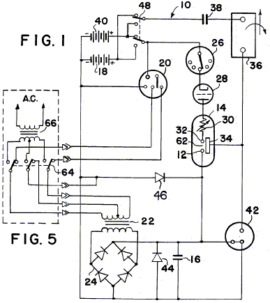
Figure 2 is an elevational sectional view of the electrical conversion element.
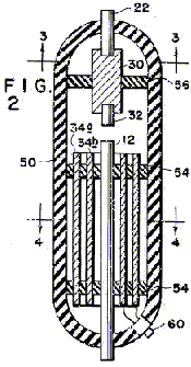
Figure 3 is a plan sectional view taken along line 3–3 of Figure 2.
Figure 4 is a plan sectional view taken along line 4–4 of Figure 2.
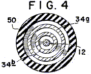
Figure 5 is a schematic circuit diagram of the alternating-current input circuit.
# Description of the Preferred Embodiment
While the present invention is susceptible of various modifications and alternative constructions, an embodiment is shown in the drawings and will herein be described in detail. It should be understood however that it is not the intention to limit the invention to the particular form disclosed; but, on the contrary, the invention is to cover all modifications, equivalents and alternative constructions falling within the spirit and scope of the invention as expressed in the appended claims.
There is disclosed herein an electrical driving system which, on theory, will convert low voltage electric energy from a source such as an electric storage battery to a high potential, high current energy pulse that is capable of developing a working force at the inductive output of the device that is more efficient than that which is capable of being developed directly from the energy source. The improvement in efficiency is further enhanced by the capability of the device to return that portion of the initial energy developed, and not used by the inductive load in the production of mechanical energy, to the same or second energy reservoir or source for use elsewhere, or for storage.
This system accomplishes the results stated above by harnessing the “electrostatic” or “impulse” energy created by a high-intensity spark generated within a specially constructed electrical conversion switching element tube. This element utilizes a low-voltage anode, a high-voltage anode, and one or more “electrostatic” or charge receiving grids. These grids are of a physical size, and appropriately positioned, as to be compatible with the size of the tube, and therefore, directly related to the amount of energy to be anticipated when the device is operating.
The low-voltage anode may incorporate a resistive device to aid in controlling the amount of current drawn from the energy source. This low-voltage anode is connected to the energy source through a mechanical commutator or a solid-state pulser that controls the timing and duration of the energy spark within the element. The high-voltage anode is connected to a high-voltage potential developed by the associated circuits. An energy discharge occurs within the element when the external control circuits permit. This short duration, high-voltage, high-current energy pulse is captured by the “electrostatic” grids within the tube, stored momentarily, then transferred to the inductive output load.
The increase in efficiency anticipated in converting the electrical energy to mechanical energy within the inductive load is attributed to the utilization of the most optimum timing in introducing the electrical energy to the load device, for the optimum period of time.
Further enhancement of energy conservation is accomplished by capturing a significant portion of the energy generated by the inductive load when the useful energy field is collapsing. This energy is normally dissipated in load losses that are contrary to the desired energy utilization, and have heretofore been accepted because no suitable means had been developed to harness this energy and restore it to a suitable energy storage device.
The present invention is concerned with two concepts or characteristics. The first of these characteristics is observed with the introduction of an energizing current through the inductor. The inductor creates a contrary force (counter-electromotive force or CEMF) that opposes the energy introduced into the inductor. This CEMF increases throughout the time the introduced energy is increasing.
In normal applications of an alternating-current to an inductive load for mechanical applications, the useful work of the inductor is accomplished prior to terminating the application of energy. The excess energy applied is thereby wasted.
Previous attempts to provide energy inputs to an inductor of time durations limited to that period when the optimum transfer of inductive energy to mechanical energy is occurring, have been limited by the ability of any such device to handle the high current required to optimize the energy transfer.
The second characteristic is observed when the energizing current is removed from the inductor. As the current is decreased, the inductor generates an EMF that opposes the removal of current or, in other words, produces an energy source at the output of the inductor that simulates the original energy source, reduced by the actual energy removed from the circuit by the mechanical load. This “regenerated”, or excess, energy has previously been lost due to a failure to provide a storage capability for this energy.
In this invention, a high-voltage, high-current, short duration energy pulse is applied to the inductive load by the conversion element. This element makes possible the use of certain of that energy impressed within an arc across a spark-gap, without the resultant deterioration of circuit elements normally associated with high energy electrical arcs.
This invention also provides for capture of a certain portion of the energy induced by the high inductive kick produced by the abrupt withdrawal of the introduced current. This abrupt withdrawal of current is attendant upon the termination of the stimulating arc. The voltage spike so created is imposed upon a capacitor that couples the attendant current to a secondary energy storage device.
A novel, but not essential, circuit arrangement provides for switching the energy source and the energy storage device. This switching may be so arranged as to actuate automatically at predetermined times. The switching may be at specified periods determined by experimentation with a particular device, or may be actuated by some control device that measures the relative energy content of the two energy reservoirs.
Referring now to Figure 1, the system 10 will be described in additional detail. The potential for the high-voltage anode, 12 of the conversion element 14 is developed across the capacitor 16. This voltage is produced by drawing a low current from a battery source 18 through the vibrator 20. The effect of the vibrator is to create a pulsating input to the transformer 22. The turns ratio of the transformer is chosen to optimize the voltage applied to a bridge-type rectifier 24. The output of the rectifier is then a series of high-voltage pulses of modest current. When the available source is already of the high voltage, AC type, it may be coupled directly to the bridge-type rectifier.
By repetitious application of these output pulses from the bridge-type rectifier to the capacitor 16, a high-voltage, high-level charge is built up on the capacitor.
Control of the conversion switching element tube is maintained by a commutator 26. A series of contacts mounted radially about a shaft, or a solid-state switching device sensitive to time or other variable may be used for this control element. A switching element tube type one-way energy path 28 is introduced between the commutator device and the conversion switching element tube to prevent high energy arcing at the commutator current path. When the switching element tube is closed, current from the voltage source 18 is routed through a resistive element 30 and a low voltage anode 32. This causes a high energy discharge between the anodes within the conversion switching element tube 14.
The energy content of the high energy pulse is electrostatically coupled to the conversion grids 34 of the conversion element. This electrostatic charge is applied through an output terminal 60 (Figure 2) across the load inductance 36, inducing a strong electromagnetic field about the inductive load. The intensity of this electromagnetic field is determined by the high electromotive potential developed upon the electrostatic grids and the very short time duration required to develop the energy pulse.
If the inductive load is coupled magnetically to a mechanical load, a strong initial torque is developed that may be efficiently utilized to produce physical work.
Upon cessation of the energy pulse (arc) within the conversion switching element tube the inductive load is decoupled, allowing the electromagnetic field about the inductive load to collapse. The collapse of this energy field induces within the inductive load a counter EMF. This counter EMF creates a high positive potential across a second capacitor which, in turn, is induced into the second energy storage device or battery 40 as a charging current. The amount of charging current available to the battery 40 is dependent upon the initial conditions within the circuit at the time of discharge within the conversion switching element tube and the amount of mechanical energy consumed by the work load.
A spark-gap protection device 42 is included in the circuit to protect the inductive load and the rectifier elements from unduly large discharge currents. Should the potentials within the circuit exceed predetermined values, fixed by the mechanical size and spacing of the elements within the protective device, the excess energy is dissipated (bypassed) by the protective device to the circuit common (electrical ground).
Diodes 44 and 46 bypass the excess overshoot generated when the “Energy Conversion Switching Element Tube” is triggered.
A switching element 48 allows either energy storage source to be used as the primary energy source, while the other battery is used as the energy retrieval unit. The switch facilitates interchanging the source and the retrieval unit at optimum intervals to be determined by the utilization of the conversion switching element tube. This switching may be accomplished manually or automatically, as determined by the choice of switching element from among a large variety readily available for the purpose.
Figure 2, 3, and 4 show the mechanical structure of the conversion switching element tube 14. An outer housing 50 may be of any insulative material such as glass. The anodes 12 and 22 and grids 34a and 34b are firmly secured by nonconductive spacer material 54, and 56. The resistive element 30 may be introduced into the low-voltage anode path to control the peak currents through the conversion switching element tube. The resistive element may be of a piece, or it may be built of one or more resistive elements to achieve the desired result.
The anode material may be identical for each anode, or may be of differing materials for each anode, as dictated by the most efficient utilization of the device, as determined by appropriate research at the time of production for the intended use.
The shape and spacing of the electrostatic grids is also susceptible to variation with application (voltage, current, and energy requirements).
It is the contention of the inventor that by judicious mating of the elements of the conversion switching element tube, and the proper selection of the components of the circuit elements of the system, the desired theoretical results may be achieved. It is the inventor’s contention that this mating and selection process is well within the capabilities of intensive research and development technique.
Let it be stated here that substituting a source of electric alternating-current subject to the required current and/or voltage shaping and/or timing, either prior to being considered a primary energy source, or thereafter, should not be construed to change the described utilization or application of primary energy in any way. Such energy conversion is readily achieved by any of a multitude of well established principles. The preferred embodiment of this invention merely assumes optimum utilization and optimum benefit from this invention when used with portable energy devices similar in principle to the wet-cell or dry-cell battery.
This invention proposes to utilize the energy contained in an internally generated high-voltage electric spike (energy pulse) to electrically energize an inductive load; this inductive load being then capable of converting the energy so supplied into a usefu1 electrical or mechanical output.
In operation the high-voltage, short-duration electric spike is generated by discharging the capacitor 16 across the spark-gap in the conversion switching element tube. The necessary high-voltage potential is stored on the capacitor in incremental, additive steps from the bridge-type rectifier 24.
When the energy source is a direct-current electric energy storage device, such as the battery 12, the input to the bridge rectifier is provided by the voltage step-up transformer 22, that is in turn energized from the vibrator 20, or solid-state chopper, or similar device to properly drive the transformer and rectifier circuits.
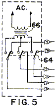
When the energy source is an alternating-current, switches 64 disconnect transformer 22 and the input to the bridge-type rectifier 24 is provided by the voltage step-up transformer 66, that is in turn energized from the vibrator 20, or solid-state chopper, or similar device to properly drive the transformer and rectifier circuits.
The repetitions output of the bridge rectifier incrementally increases the capacitor charge toward its maximum. This charge is electrically connected directly to the high-voltage anode 12 of the conversion switching element tube.
When the low-voltage anode 32 is connected to a source of current, an arc is created in the spark-gap designated 62 of the conversion switching element tube equivalent to the potential stored on the high-voltage anode, and the current available from the low-voltage anode. Because the duration of the arc is very short, the instantaneous voltage, and instantaneous current may both be very high. The instantaneous peak apparent power is therefore, also very high. Within the conversion switching element tube, this energy is absorbed by the grids 34a and 34b mounted circumferentially about the interior of the tube.
Control of the energy spike within the conversion switching element tube is accomplished by a mechanical, or solid-state commutator, that closes the circuit path from the low-voltage anode to the current source at that moment when the delivery of energy to the output load is most auspicious. Any number of standard high-accuracy, variable setting devices are available for this purpose. When control of the repetitive rate of the system’s output is required, it is accomplished by controlling the time of connection at the low-voltage anode.
Thus there can be provided an electrical driving system having a low-voltage source coupled to a vibrator, a transformer and a bridge-type rectifier to provide a high voltage pulsating signal to a first capacitor. Where a high-voltage source is otherwise available, it may be coupled direct to a bridge-type rectifier, causing a pulsating signal to a first capacitor. The capacitor in turn is coupled to a high-voltage anode of an electrical conversion switching element tube. The element also includes a low-voltage anode which in turn is connected to a voltage source by a commutator, a switching element tube, and a variable resistor.
Mounted around the high-voltage anode is a charge receiving plate which in turn is coupled to an inductive load to transmit a high-voltage discharge from the element to the load. Also coupled to the load is a second capacitor for storing the back EMF created by the collapsing electrical field of the load when the current to the load is blocked. The second capacitor in turn is coupled to the voltage source.
# Claims
What is claimed is:
1. An electrical driving system comprising: a source of electrical voltage; a vibrator connected to said source for forming a pulsating signal; a transformer connected to said vibrator for receiving said pulsating signal; a rectifier connected to said transformer having a high-voltage pulse output; a capacitor for receiving said voltage pulse output; a conversion switching element tube having first and second anodes, electrically conductive means for receiving a charge positioned about said second anode and an output terminal connected to said charge receiving means, said second anode being connected to said capacitor; a commutator connected to said source of electrical voltage and to said first anode; and an inductive load connected to said output terminal whereby a high energy discharge between said first and second anodes is transferred to said charge receiving means and then to said inductive load.
2. A system as claimed in claim 1, including a second capacitor for receiving a charge from said load.
3. A system as claimed in claim 2, including a switching element tube positioned in series between said commutator and said first anode.
4. A system as claimed in claim 3, including a second source of voltage and a switch for receiving a signal from said second capacitor.
5. A system as claimed in claim 4 wherein: said conversion switching element tube includes a resistive element in series with said first anode; and said charge receiving means is tubularly shaped.
6. A system as in claim 1 wherein said source comprises a direct current source and wherein said system further comprises:a source of alternating current; and a switch means for selecting said direct-current or said alternating-current power source as input to said rectifier.
7. A system as in claim 1 wherein said rectifier comprises a bridge-type rectifier.
8. A method for providing power to an inductive load comprising the steps of providing a voltage source; pulsating a signal from said source; increasing the voltage of said signal; rectifying said signal; storing and increasing said signal; conducting said signal to a high-voltage anode; providing a low-voltage to a second anode to form a high energy discharge; electrostatically coupling said discharge to a charge receiving element; conducting said discharge to an inductive load; coupling a second capacitor to said load; and coupling said capacitor to said source.
## US Patent # 4,661,747 ; Efficient Electrical Conversion Switching Tube Suitable for Inductive Loads ; Edwin V.Gray, Sr.
# Abstract
Disclosed is an electrical driving and recovery system for a high frequency environment. The recovery system can be applied to drive present day direct-current or alternating-current loads for better efficiency. It has a low-voltage source coupled to a vibrator, a transformer and a bridge-type rectifier to provide a high voltage pulsating signal to a first capacitor. Where a high-voltage source is otherwise available, it may be coupled directly to a bridge-type rectifier, causing a pulsating signal to the first capacitor. The first capacitor in turn is coupled to a high voltage anode of an electrical conversion switching element tube. The switching element tube also includes a low voltage anode which is connected to a voltage source by a commutator and a switching element tube. Mounted around the high voltage anode is a charge receiving plate which is coupled to an inductive load to transmit a high voltage discharge from the switching element tube to the load. Also coupled to the load is a second capacitor for storing the back EMF created by the collapsing electrical field of the load when the current to the load is blocked. The second capacitor is coupled to the voltage source. When adapted to present day direct-current or alternating-current devices the load could be a battery or capacitor to enhance the productivity of electrical energy.
Inventors: Gray, Sr.; Edwin V. (P.O. Box 362, Council, ID 83612) ; Appl. No.: 791508 ~ Filed: October 25, 1985
# References Cited:
U.S. Patent Documents:
– 3,443,142 (May 1969) Koppl, et al. (315/58.)
– 3,663,855 (May 1972) Boettcher (315/330)
– 3,798,461 (Mar. 1974) Edson (315/36)
– 3,939,379 (Feb. 1976) Sullivan, et al. (315/330)
– 4,198,590 (Apr. 1980) Harris (315/335)
– 4,370,597 (Jan. 1983) Weiner, et al. (315/58)
Foreign Patent Documents : 0540,361 (Dec. 1976) SU 315/335.
# Background of the Invention
1. Field of the Invention:
The present invention relates to an electrical driving system and a conversion element, and more particularly, to a system for driving an inductive load in a greatly improved and efficient manner.
2. Description of the Prior Act:
In the opinion of the inventor, there is no known device which provides the conversion of energy from a direct-current electric source or an alternating-current electric source to a mechanical force based on the principle of this invention. EXAMPLE: A portable energy source, (1) such as a battery, (2) such as alternating-current, (3) such as the combination of battery and alternating-current, may be used with highly improved efficiency to operate a mechanical device, whose output is a linear or rotary force, with an attendant increase in the useful productive period between external applications of energy restoration for the energy source.
# Summary of the Invention
The present invention provides a more efficient driving system comprising a source of electrical voltage; a vibrator connected to the low-voltage source for forming a pulsating signal; a transformer connected to the vibrator for receiving the pulsating signal; a high-voltage source, where available, connected to a bridge-type rectifier; or the bridge-type rectifier connected to the high voltage pulse output of the transformer; a capacitor for receiving the voltage pulse output; a conversion element having first and second anodes, electrically conductive means for receiving a charge positioned about the second anode and an output terminal connected to the charge receiving means, the second anode being connected to the capacitor; a commutator connected to the source of electrical voltage and to the first anode; and an inductive load connected to the output terminal whereby a high energy discharge between the first and second anodes is transferred to the charge receiving means and then to the inductive load.
As a sub-combination, the present invention also includes a conversion element comprising a housing; a first low voltage anode mounted to the housing, the first anode adapted to be connected to a voltage source; a second high voltage anode mounted to the housing, the second anode adapted to be connected to a voltage source; electrically conductive means positioned about the second anode and spaced therefrom for receiving a charge, the charge receiving means being mounted to the housing; and an output terminal communicating with the charge receiving means, said terminal adapted to be connected to an inductive load.
The invention also includes a method for providing power to an inductive load comprising the steps of providing a voltage source, pulsating a signal from said source; increasing the voltage of said signal; rectifying said signal; storing and increasing the signal; conducting said signal to a high voltage anode; providing a low voltage to a second anode to form a high energy discharge; electrostatically coupling the discharge to a charge receiving element; conducting the discharge to an inductive load; coupling a second capacitor to the load; and coupling the second capacitor to the source.
It is an aim of the present invention to provide a system for driving an inductive load which system is substantially more efficient than any now existing.
Another object of the present invention is to provide a system for driving an inductive load which is reliable, is inexpensive and simply constructed .
The foregoing objects of the present invention together with various other objects, advantages, features and results thereof which will be evident to those skilled in the art in light of this disclosure may be achieved with the exemplary embodiment of the invention described in detail hereinafter and illustrated in the accompanying drawings.
# Brief Description of the Drawings
Figure 1 is a schematic circuit diagram of the electrical driving system.
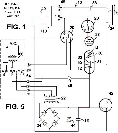
Figure 2 is an elevational sectional view of the electrical conversion element.
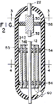
Figure 3 is a plan sectional view taken along line 3–3 of Figure 2.
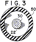
Figure 4 is a plan sectional view taken along line 4–4 of Figure 2.
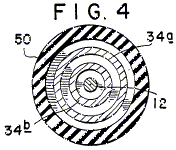
Figure 5 is a schematic circuit diagram of the alternating-current input circuit.
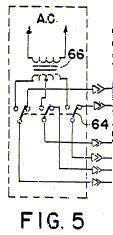
# Description of the Preferred Embodiment
While the present invention is susceptible of various modifications and alternative constructions, an embodiment is shown in the drawings and will herein be described in detail. It should be understood however that it is not the intention to limit the invention to the particular form disclosed; but, on the contrary, the invention is to cover all modifications, equivalents and alternative constructions falling within the spirit and scope of the invention as expressed in the appended claims.
There is disclosed herein an electrical driving system which, on theory, will convert low voltage electric energy from a source such as an electric storage battery to a high potential, high current energy pulse that is capable of developing a working force at the inductive output of the device that is more efficient than that which is capable of being developed directly from the energy source. The improvement in efficiency is further enhanced by the capability of the device to return that portion of the initial energy developed, and not used by the inductive load in the production of mechanical energy, to the same or second energy reservoir or source for use elsewhere, or for storage.
This system accomplishes the results stated above by harnessing the “electrostatic” or “impulse” energy created by a high-intensity spark generated within a specially constructed electrical conversion switching element tube. This element utilizes a low-voltage anode, a high-voltage anode, and one or more “electrostatic” or charge receiving grids. These grids are of a physical size, and appropriately positioned, as to be compatible with the size of the tube, and therefore, directly related to the amount of energy to be anticipated when the device is operating.
The low-voltage anode may incorporate a resistive device to aid in controlling the amount of current drawn from the energy source. This low-voltage anode is connected to the energy source through a mechanical commutator or a solid-state pulser that controls the timing and duration of the energy spark within the element. The high-voltage anode is connected to a high-voltage potential developed by the associated circuits. An energy discharge occurs within the element when the external control circuits permit. This short duration, high-voltage, high-current energy pulse is captured by the “electrostatic” grids within the tube, stored momentarily, then transferred to the inductive output load.
The increase in efficiency anticipated in converting the electrical energy to mechanical energy within the inductive load is attributed to the utilization of the most optimum timing in introducing the electrical energy to the load device, for the optimum period of time.
Further enhancement of energy conservation is accomplished by capturing a significant portion of the energy generated by the inductive load when the useful energy field is collapsing. This energy is normally dissipated in load losses that are contrary to the desired energy utilization, and have heretofore been accepted because no suitable means had been developed to harness this energy and restore it to a suitable energy storage device.
The present invention is concerned with two concepts or characteristics. The first of these characteristics is observed with the introduction of an energizing current through the inductor. The inductor creates a contrary force (counter-electromotive force or CEMF) that opposes the energy introduced into the inductor. This CEMF increases throughout the time the introduced energy is increasing.
In normal applications of an alternating-current to an inductive load for mechanical applications, the useful work of the inductor is accomplished prior to terminating the application of energy. The excess energy applied is thereby wasted.
Previous attempts to provide energy inputs to an inductor of time durations limited to that period when the optimum transfer of inductive energy to mechanical energy is occurring, have been limited by the ability of any such device to handle the high current required to optimize the energy transfer.
The second characteristic is observed when the energizing current is removed from the inductor. As the current is decreased, the inductor generates an EMF that opposes the removal of current or, in other words, produces an energy source at the output of the inductor that simulates the original energy source, reduced by the actual energy removed from the circuit by the mechanical load. This “regenerated”, or excess, energy has previously been lost due to a failure to provide a storage capability for this energy.
In this invention, a high-voltage, high-current, short duration energy pulse is applied to the inductive load by the conversion element. This element makes possible the use of certain of that energy impressed within an arc across a spark-gap, without the resultant deterioration of circuit elements normally associated with high energy electrical arcs.
This invention also provides for capture of a certain portion of the energy induced by the high inductive kick produced by the abrupt withdrawal of the introduced current. This abrupt withdrawal of current is attendant upon the termination of the stimulating arc. The voltage spike so created is imposed upon a capacitor that couples the attendant current to a secondary energy storage device.
A novel, but not essential, circuit arrangement provides for switching the energy source and the energy storage device. This switching may be so arranged as to actuate automatically at predetermined times. The switching may be at specified periods determined by experimentation with a particular device, or may be actuated by some control device that measures the relative energy content of the two energy reservoirs.
Referring now to Figure 1, the system 10 will be described in additional detail. The potential for the high-voltage anode 12 of the conversion element 14 is developed across the capacitor 16. This voltage is produced by drawing a low current from a battery source 18 through the vibrator 20. The effect of the vibrator is to create a pulsating input to the transformer 22. The turns ratio of the transformer is chosen to optimize the voltage applied to a bridge-type rectifier 24. The output of the rectifier is then a series of high-voltage pulses of modest current. When the available source is already of the high voltage AC type, it may be coupled directly to the bridge-type rectifier.
By repetitious application of these output pulses from the bridge-type rectifier to the capacitor 16, a high-voltage high-level charge is built up on the capacitor.
Control of the conversion switching element tube is maintained by a commutator 26. A series of contacts mounted radially about a shaft, or a solid-state switching device sensitive to time or other variable may be used for this control element. A switching element tube type one-way energy path 28 is introduced between the commutator device and the conversion switching element tube to prevent high energy arcing at the commutator current path. When the switching element tube is closed, current from the voltage source 18 is routed through a resistive element 30 and a low voltage anode 32. This causes a high energy discharge between the anodes within the conversion switching element tube 14.
The energy content of the high energy pulse is electrostatically coupled to the conversion grids 34 of the conversion element. This electrostatic charge is applied through an output terminal 60 (Figure 2) across the load inductance 36, inducing a strong electromagnetic field about the inductive load. The intensity of this electromagnetic field is determined by the high electromotive potential developed upon the electrostatic grids and the very short time duration required to develop the energy pulse.
If the inductive load is coupled magnetically to a mechanical load, a strong initial torque is developed that may be efficiently utilized to produce physical work.
Upon cessation of the energy pulse (arc) within the conversion switching element tube the inductive load is decoupled, allowing the electromagnetic field about the inductive load to collapse. The collapse of this energy field induces within the inductive load a counter EMF. This counter EMF creates a high positive potential across a second capacitor 38 which, in turn, is induced into the second energy storage device or battery 40 as a charging current. The amount of charging current available to the battery 40 is dependent upon the initial conditions within the circuit at the time of discharge within the conversion switching element tube and the amount of mechanical energy consumed by the work load.
A spark-gap protection device 42 is included in the circuit to protect the inductive load and the rectifier elements from unduly large discharge currents. Should the potentials within the circuit exceed predetermined values, fixed by the mechanical size and spacing of the elements within the protective device, the excess energy is dissipated (bypassed) by the protective device to the circuit common (electrical ground).
Diodes 44 and 46 bypass the excess overshoot generated when the “Energy Conversion Switching Element Tube” is triggered.
A switching element 48 allows either energy storage source to be used as the primary energy source, while the other battery is used as the energy retrieval unit. The switch facilitates interchanging the source and the retrieval unit at optimum intervals to be determined by the utilization of the conversion switching element tube. This switching may be accomplished manually or automatically, as determined by the choice of switching element from among a large variety readily available for the purpose.
Figures 2, 3, and 4 show the mechanical structure of the conversion switching element tube 14. An outer housing 50 may be of any insulative material such as glass. The anodes 12 and 32 and grids 34a and 34b are firmly secured by nonconductive spacer material 54, and 56. The resistive element 30 may be introduced into the low-voltage anode path to control the peak currents through the conversion switching element tube. The resistive element may be of a piece, or it may be built of one or more resistive elements to achieve the desired result.
The anode material may be identical for each anode, or may be of differing materials for each anode, as dictated by the most efficient utilization of the device, as determined by appropriate research at the time of production for the intended use.
The shape and spacing of the electrostatic grids is also susceptible to variation with application (voltage, current, and energy requirements).
It is the contention of the inventor that by judicious mating of the elements of the conversion switching element tube, and the proper selection of the components of the circuit elements of the system, the desired theoretical results may be achieved. It is the inventor’s contention that this mating and selection process is well within the capabilities of intensive research and development technique.
Let it be stated here that substituting a source of electric alternating-current subject to the required current and/or voltage shaping and/or timing, either prior to being considered a primary energy source, or thereafter, should not be construed to change the described utilization or application of primary energy in any way. Such energy conversion is readily achieved by any of a multitude of well established principles. The preferred embodiment of this invention merely assumes optimum utilization and optimum benefit from this invention when used with portable energy devices similar in principle to the wet-cell or dry-cell battery.
This invention proposes to utilize the energy contained in an internally generated high-voltage electric spike (energy pulse) to electrically energize an inductive load; this inductive load being then capable of converting the energy so supplied into a useful electrical or mechanical output. In operation the high-voltage, short-duration electric spike is generated by discharging the capacitor 16 across the spark-gap in the conversion switching element tube. The necessary high-voltage potential is stored on the capacitor in incremental, additive steps from the bridge-type rectifier 24.
When the energy source is a direct-current electric energy storage device, such as the battery 12, the input to the bridge rectifier is provided by the voltage step-up transformer 22, that is in turn energized from the vibrator 20, or solid-state chopper, or similar device to properly drive the transformer and rectifier circuits.
When the energy source is an alternating-current, switches 64 disconnect transformer 22 and the input to the bridge-type rectifier 24 is provided by the voltage step-up transformer 66, that is in turn energized from the vibrator 20, or solid-state chopper, or similar device to properly drive the transformer and rectifier circuits.
The repetitious output of the bridge rectifier incrementally increases the capacitor charge toward its maximum. This charge is electrically connected directly to the high-voltage anode 12 of the conversion switching element tube.
When the low-voltage anode 32 is connected to a source of current, an arc is created in the spark-gap designated 62 of the conversion switching element tube equivalent to the potential stored on the high-voltage anode, and the current available from the low-voltage anode. Because the duration of the arc is very short, the instantaneous voltage, and instantaneous current may both be very high. The instantaneous peak apparent power is therefore, also very high. Within the conversion switching element tube, this energy is absorbed by the grids 34a and 34b mounted circumferentially about the interior of the tube.
Control of the energy spike within the conversion switching element tube is accomplished by a mechanical, or solid-state commutator, that closes the circuit path from the low-voltage anode to the current source at that moment when the delivery of energy to the output load is most auspicious. Any number of standard high-accuracy, variable setting devices are available for this purpose. When control of the repetitive rate of the system’s output is required, it is accomplished by controlling the time of connection at the low-voltage anode.
Thus there can be provided an electrical driving system having a low-voltage source coupled to a vibrator, a transformer and a bridge-type rectifier to provide a high voltage pulsating signal to a first capacitor. Where a high-voltage source is otherwise available, it may be coupled direct to a bridge-type rectifier, causing a pulsating signal to a first capacitor. The capacitor in turn is coupled to a high-voltage anode of an electrical conversion switching element tube. The element also includes a low-voltage anode which in turn is connected to a voltage source by a commutator, a switching element tube, and a variable resistor.
Mounted around the high-voltage anode is a charge receiving plate which in turn is coupled to an inductive load to transmit a high-voltage discharge from the element to the load. Also coupled to the load is a second capacitor for storing the back EMF created by the collapsing electrical field of the load when the current to the load is blocked. The second capacitor in turn is coupled to the voltage source.
# Claims
What is claimed is:
1. An electrical conversion switching element tube comprising: a closed insulative housing (50); a first low-voltage anode (32) mounted internally to said housing and extending internally to an electrical discharge area (62), said first anode adapted to be connected to a voltage source external to the housing; a second high-voltage anode (12) mounted internally to said housing and extending internally to said electrical discharge area (62), said second anode also being adapted to be connected to a voltage source external to the housing; electrically conductive means (34b) positioned internally within said housing and extending circumferentially about said second anode while being directly exposed thereto but not conductively connected thereto but, rather, spaced therefrom for receiving an electrostatic charge from the second anode when a discharge current is triggered across said discharge area between said first and second anodes, said charge receiving electrically conductive means also being internally mounted to said housing; and an output terminal (60) communicating with said charge receiving electrically conductive means, said terminal adapted to be connected to an inductive load externally of said housing.
2. An electrical conversion switching element tube as claimed in claim 1, including a resistive element (30) in series with said first anode.
3. An electrical conversion switching element tube as claimed in claim 1 wherein: said charge receiving electrically conductive means is tubularly shaped.
4. An electrical conversion switching element tube as claimed in claim 3, including a second tubularly shaped charge receiving electrically conductive means (34a) positioned circumferentially about said first mentioned charge receiving electrically conductive means.