MEMO 8, Memo WFC 427
http://users.skynet.be/fa272699/Energie/Meyer/memos/section8.pdf
Voltage Wave-Guide Propagating ; “Resonant Action” By Voltage Tickling of State Space
The “Mode of Operability” of determining the “Operational Parameters of adjusting thermal explosive energy (gtnt) exiting Water Fuel Injector nozzle-port is directly related to the type of Voltage Pulse Train being used and the geometrical configuration of the Resonant Cavity.
Combining “Electrical Voltage Parameters” with “Physical Design Parameters” of a given type of Resonant Cavity allows the energy-yield of the Hydrogen Gas Flame Front to be either more or less Thermal Explosive Energy (gtnt) over thermal heat energy and herein is called “Energy Vectoring” … and is performed in the following way:
The “mode-of-operability” of determining the “operational parameters” of releasing thermal explosive energy (gtnt) (flame force-yield) in direct relationship to thermal heat-yield (flame temperature) beyond applied voltage pulse-frequency of opposite polarity intensity (farthest from state of equilibrium) is effectuated by simply changing or altering the physical configuration of the “Voltage Wave-guides” (Resonant Cavity structure of design) in direct reference to applied ever changing Unipolar Voltage Amplitude Pulse-Wave (see Figure 6-3 of WFC memo 425) to bring-on and propagate a predetermine flamedensity of projection by preselecting the “State Space” in which the injected and incoming water bath is subjected to … performing work of instantly converting water into thermal explosive energy (gtnt) on demand … using water as fuel. The established “State Space” is governed by either one of two variables being of either “Static” or “Dynamic” state of condition. Dynamic State condition is a variable of condition that is changing all the time; whereas, Static variable of condition is set at some point but then never changes. A point in “State Space” represents the state of the flame-system at a given time and is either in an synchronized and synchrony movement. Interaction of either ” Static State Space” or “Dynamic State Space” in similar state of conditions or opposite conditions of “states” allows “Energy-Vectoring” of the hydrogen flame-front or flame projection of trajectory … establishing an interrelationship on how to design retrofit the water fuel injector ® to any existing type of energy consuming device.
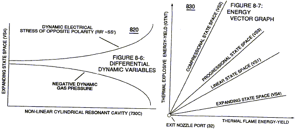
Static variables condition is established when the resultant gas pressure is held constant with the never changing static electrical stress of opposite polarity of Voltage Pulse-Wave (64) of Figure (3-20) of WFC memo 422DA. Dynamic variable conditions exists when both the applied electrical stress of opposite polarity and dynamic gas pressure are continually changing in a preset time frame. Where, Combinatorial variables conditions is a “State Space” function of subjecting constant static gas pressure to an ever changing electrical stress of opposite polarity (RR’-SS’). And, Differential dynamic variables condition of “State Space” is accomplished whenever changing dynamic electrical stress of opposite polarity (RR’-SS’) encounters a negative (decrease/drop-in) dynamic gas pressure. In each and all “Space State” of changes, the combustible gas atoms of water is/are “Electrically Stress” under “different” pressure levels to bring-on the triggering point of thermally igniting the combustible gases of water beyond or away from “Stable State” of Equilibrium. Voltage Tickling of State Space under “Resonant Electrical Stress” without amp influxing while “Tuning-ln” to the dielectric properties of water is herein referred to in this WFC Tech-manual as “Resonant Action.”
Traveling Voltage Wave-Guides
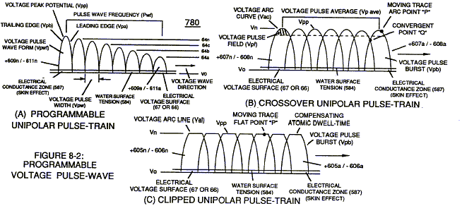
The formation of tubular Traveling Voltage Wave-guide (570a).of Figure (7-12) (WFC memo 426) as to (770) of Figure (8-1) is physically formed when positive electrical voltage surface (661E9) and negative electrical voltage surface (671E 10) are placed in parallel space relationship to form voltage swfaces (E91E1O) about an cylindrical axis of rotation having space-gap (35) there between … and thus, fanning Cylindrical Resonant Cavity (730A) of Figure (7-12) as to (770A) of Figure (8-1) when space-gap (616) of Figure (720) exposes injected water bath (85) to unipolar puIse-oscillation of high voltage intensity of opposite polarity (67/66) as to (780) of Figure (8-2) which, in turn, propagates opposite electrical attraction force (RR’ _ 88′) of Figure (7-4), as illustrated in (590) of Figure (6-2) as to (585) of Figure (8-1). The dielectric property of water (85) (resistance to electron flow) in conjunction with VIC Coil Matrix Circuit (690) of Figure (7-8) (WFC memo 426) as to VIC Coil Assembly (580) of Figure (6-1) (WFC memo 425) ability to inhibit amp “influxing” (Electron Bounce Phenomenon EbP) during pulsing operations (49a xx 49n) allows voltage amplitude of pulse-frequency potential (T1a xxx T1n) as to (Vo -64a-64b -64c – Vn) of (780A) Figure (8-2) to be applied across cross-sectional circularring water bath (85) (donut shape) to cause Voltage Wave-Form (57) of Figure (6-2) to travel the entire longitudinal length of water-gap (616) since stainless steel material (s/s) (T304) forming Voltage surfaces (E9/E1O) electrically conducts and transfers (skin effect) Voltage Pulse-Freqnency Potential (583) alone the inside surface area of the chemically inert and non-oxidizing stainless steel (s/s) tubular materia1 (E9/E1O) which physically dictates the shape and configuration of voltage waves (66/67) … forming tubular voltage wave-guide (s) (570) of Figure (7-12) that, now, becomes the same physical configuration of Water Gap (616), as i11ustrated in (720) of Figure (7-11).
The surface tension of water (584) adjacent to both voltage surfaces (E9IEIO) further aids the transmission of voltage potential (66/67) since Electrical Charging Effect (585) of Figure (7-4) does not change or alter the dielectric value of water (Re). Together, the Voltage Coefficient of Water (e/Eo) of Equation (Eq 21) and the Voltage Coefficient of the stainless steel (s/s) material funning voltage surfaces (E9/EIO), now, allows the establishment and performance of Traveling Electtica1 VoItage Wave-Guide (583/602) since electrical conductance zone (587) between electrical surface (S) (E9IEI0) and the dielectric surface tension of water (584) acts and performs as a electrical conductor (Skin Effect) … since electrical transmission zone (587) is almost free of electron leakage … since Water Bath (85) is a dielectric-liquid (typically 78.54Q) that does not like to transfer nor exchange electrons … thereby, maintaining voltage amplitude potential (VO _ 64a _ 64b –64c – Vn) of Figure (8-6) without experiencing amp arc-over across Water-Gap (616) in any appreciable amount … allowing pulsating opposite electrical attraction forces (RR’ _ SS’) to perform the work of “Electrically Charging” water bath (85) to bring-on and trigger Hydrogen Fracturing Process (90) of Figure (5-5), as illustrated in Energy Pumping stage (520) of Figure (5-3). Voltage Intensifier Matrix Circuit (690) of Figure (7-8) electrically connected with resistive liquid (85/Re) (forming Resonant Water Gap Q2 of Figure 7-8) propagates the transmission of Traveling Voltage Wave-Form (57) of Figure (6-2) as to (770) of Figure (8-1) by the functional Stanley A. Meyer 8-3 relationship of Circuit Resistance Equation (Eq 9) during programmable Voltage Pulsing operations (49a xxx 1’3 xxx49n) of Figure (8-2).
Electrical Voltage-Pulse Wave-Transmission (583a xxx 583n), now formed, occurs along Electrical Conductance Zone (587) since applied Electrical Pulse Voltage amplitude (Vo – 64a – 64b – 64c – Vn) is time responsive (T1/T2a – T3 T1/T2n) to incoming gated Voltage Pulse Frequency (49a xxx – 1’3 – xxx 49n). Each Voltage Pulse duration time-period (T1 on time) from start to finish is directly related to applied Voltage-Pulse Amplitude (Vo xxx Vn) and reoccurring Voltage Pulse Frequency (49a xxx 49n) forming “Unipolar Voltage Pulse-Wave” (583) from zero voltage ground state (Vo) to a predetermined Voltage Level ( xxx 64 x – 64y – 64z – Vn) on the leading edge of the Voltage Pulse-Wave (Vpa) and, then, reversing voltage up swing to drop on the trailing edge (Vpb), completing Voltage-wave (583). The newly established leading voltage edge (Vpa) and trailing voltage edge (Vpb) being uniform in shape/configuration since both Resonant Charging Chokes (56/Z2 62/Z3) resistive values are the same (Typically 11.6 k each) and incoming signal (49a xxx 49n) is electrically linked with Water-Gap Capacitor (Cp) of Figure (7-8) having dielectric liquid of Water (85) there between … Thereby, preventing coil-ringing during each pulse off-time … allowing Electron Bounce Phenomenon (EbP) to occur without amp influxing within VIC Matrix Circuit (690) of Figure (7-8) as so governed by Circuit Resistance Equations (Eq. 9) which, in activated electrical-state, allows positive Voltage Pulse-Wave (583) to be duplicated in succession to form Voltage Pulse Train (66 – 583a xxx 583n), as illustrated in (770) of Figure (8-1). Opposite negative Voltage Pulse Train (67 – 602a xxx 602n) is similarly formed since “Electron Clustering Effect” (631) of Figure (7-9) produces a “Negative Electrical Voltage Intensity (67) in equal magnitude to the “Positive Electrical Voltage Intensity (66) during :=ach/repetitious magnetic pulsecycle (Rp/71). Remember, Secondary Voltage pickup coil (52) of Figure (7-8) displaces and separates Resonant Charging Chokes (56/62) on opposite end of said Secondary Pickup Coil (52).
State Space (Sp)
During the electrical-formation (66- Vpa/Vpb – 67- Vpa/Vpb) of each opposite Electrical Voltage? 1:ise-Wave (66-583 – 67-602), opposite electrical attraction force (RR’ – SS’) of Figure (7-4) is produced across water cap (Cp) of Figure (7-8) which, now, sets up and defines the conditions of State Space,” as illustrated in (770AIB) of Figure (8-1) as to (650) of Figure (7-4). The newly formed Opposite Electrical Attraction Force (RR’ – SS’) intensity is directly related to the applied Voltage Amplitude Burst-Time (Vpa – Vn -Vpb) as to the Voltage Burst-Frequency (49a xxx 49n) as to Voltage Peak Excursion Point “P” at the height of Unipolar Voltage Pulse Wave (583/602) which, in turns, determines maximum Voltage Peak-Potential (Vpp) at any given time during each Voltage Pulsing Cycle (Vpa/Vpb). Electrical Attraction Force intensity (RR’ – SS’ as to RU/RU’ – ST/ST’ as to 550 of Figure 5-8) at Peak Voltage Potential (Vpp) is either increasing or decreasing or remaining constant as to Voltage Peak Excursion Point “P” trace-position which scans the exact bltagePu1se Wave-Form (66- 583/67-602) being produced, as illustrated in (780B) of Figure (82). Equalizing Voltage Pulse-Scan (Bps) from start of one Voltage Pulse-Field (Vpf) to the start of next Voltage Pulse-Field (Vpfa + Vpfb + Vpfc + Vpfn) is determined by the total average of the number of applied Voltage-Pulses (Vp ave.) making up opposite Voltage Pulse Train (583/602a xxx 583/602n) in synchronous movement. Generally speaking, Arc Curve (Vac) changing /varying to Arc-Line (Val) of Unipolar Voltage Pulse Wave-form (Vpwf) defines Voltage Pulse Field (Vpf) scan profile (Vsp) by which Trace-point “P” determines the type of “State Space” being used to propagate “Voltage Tickling” of water molecule (85) undergoing “Electrical Stress” under different fluid-pressures.
Whenever, Voltage Excursion Point “P” is always changing in a given space-time, “State Space” is referred to as Dynamic State Space;” whereas, “Static State Space” exists when Voltage Excursion Point “P” remains constant during a precise period of space-time at Peak Voltage Potential (Vpp) forming clipped Voltage Pulse Wave-form (Vcwf) during Voltage Pulse Shaping by way of Programmable Pulsing Circuit (WFC project 422DA/423DA) electrically interfaced with VIC Matrix Circuit (690), as illustrated in (780) of Figure (8-2). Dynamic State Space causes Opposite Electrical Attraction Force (RR’ – SS’) to continually vary in electrical intensity (RR’SS’ cei) as to formation of Voltage Peak Curve (Vpc); wherein, Static State Space allows Opposite Attraction Force (RR’ -SS’) to remain at constant electrical intensity (RR’ – SS’cei) when Peak Voltage Potential (Vpp) is clipped in forming Arc-Line (Val), as illustrated in (780C) of Figure (82). Crossover Unipolar Pulse Train (780B) is used when particle oscilIation of the water molecule atom (s) is/are to be continually electrical stressed (RR’ -SS’ vei) under changing conditions of higher magnitude (Compressing Voltage Pulse Wave-form) than the use of Planar Unipolar Pulse Train (780A). Clipped Unipolar Pulse Train (780C) is used to encourage further increase in atomic dwell-time capable of raising Atomic Energy Level (AEI) of the Water Atoms to even a higher energy-state before Snapping-Action occurs when Unipolar Pulse Wave (Upw) returns to ground state (Vo) after voltage propagation (Vpa/Vpb). Of course, the repetition-rate of.”Atomic SnappingAction” (Asa) (the number of Voltage Pulse Fields Vpf occurring per unit of space-time) directly determines the resultant energy level of Static Electrical Charging Effect (585) of Figure (8-1) since Particle Oscillation” is being used as a Energy Generator” (EGpo), as so subscribed in WFC memo (424) titled Atomic Energy Balance of Water as to the functional parameters associated with Dynamic Voltage Potential Wave-form (600) of Figure (6-3) … which uses Voltage Pulse Potential of opposite electrical polarity of attraction (RR’ – SS’ as to RU/RU’ ST/DST’) to perform work in the following sequence of events in an instant of time: Electrical Polarization Process (160) (elongating the water molecule … changing the time share rate of the covalent electrons … switching off the covalent bond by attenuating the electromagnetic fields of the electrical stressed atoms undergoing molecule separation; Universal Energy Priming Stage (500) (particle oscillation as a energy generator by deflecting atomic particles under changing electrical stress); Liquid to Gas Ionization Stage (230) (ejecting electrons from the atomic structure under divergent electrical stress); and Thermal Gas Triggering Stage (E9d) (gas igniting the electrically stress combustible gas atoms farthest from the state of electrical equilibrium) … triggering Hydrogen Fracturing Process (90) (subcritical-state combustible gases being spark-ignited under Electrical Resonance of Stress).
In terms of Particle Oscillation (Poe) as a Energy-Generator (EGpo), if Voltage Arc Line (Val) length is extended while Voltage Amplitude (xx 64a – 64b – 64c – Vn) is adjusted to higher Voltage Peak-Potential (Vpp) then greater atomic interaction (585) of Figure (8-1) (see WFC memo 424 titled Atomic Energy Balance of Water, once again) occurs when particle oscillation (Poe) of deflection of atomic mass (see 550 of Figure 5-8) (atom elongation) is electrically stressed farthest from the point of state of atomic-equilibrium by way of opposite Voltage Electrical Attraction Force (RR’ – SS’ as to RU/RU’ – ST/ST’), as further illustrated in (500) of Figure (5-1) as to (510) of Figure (5-2). Voltage Tickling of State Space under “Resonant Electrical Stress” without amp influxing while ”Tuning-~” to the dielectric properties of water is herein referred to in this WFC Tech-manual as “Resonant Action,” as illustrated graphically in Figure (5-4 A,B,C) as to Resonant Cavity (170) of Figure (3-25) as to Figure (1-13).
Energy Vectoring (Ev)
The “mode of operability” of determining the “Operational Parameters” of adjusting the thermal explosive energy (gtnt) exiting from nozzle-port (32) of Figure (4-5) as to (40) of Figure (4-2) is directly related to the characteristics of the applied Voltage Pulse Potential (Vpp) Wave-form (s) (Vpwt) and the geometrical configuration of Resonant Cavity (90) of Figure (4-7) as to (730) of Figure (7-12). In terms of Voltage Pulse Wave-form (s) (Vpwt) several ”Electrical Operational Parameters” exists: Dynamic State Space (Dss) which continually changes/varies Electrical Attraction Force (RR’ – SS’ as to RUIRU’ – ST/ST’) from low stress intensity (S-low) to high stress intensity (S- high) and back to low stress point (S-low) as to Arc Curve (Vac) forming Voltage Pulse Field (Vpt) atop Voltage Pulse Burst (Vpb) … which combined together (Vpf + Vpb) Electrical Stress (Es) variances corresponds to the Voltage Pulse Shape of each synchronized opposite Voltage Pulse Wave (583 – 602) of (770A) of Figure (8-1) being produced during applied Voltage Pulse Operation (49a xxx 49n); Static State Space (Sss) is the electrical condition by which Electrical Attraction Force (RR’ – SS’ as to RU/RU’ – ST/ST’) is being held constant once Voltage Pulse Burst Vpb) occurs during Voltage Pulsing Operation (Vpwf) … forming synchronized Clipped Voltage Wave-form (780C) of Figure (8-2) in like manner to voltage sync-pulse (583 – 602).
In the area of Voltage Sync-Wave (+/-) propagation, Unipolar Voltage Pulse Train (583/602a xxx 583/602) of (770A) of Figure (8-1), clipped Voltage Pulse Train (605/606a xxx 605/606n) of Figure (780C) of Figure (8-2), and Crossover Unipolar Pulse Train (607/608a xxx 607/608n) bringson Static Voltage Stimulation (Vsvs) by which Static Electrical Charging Effect (585) is being held constant since Electrical Stress Force (Est) averages out either Dynamic State Space (Dss) or Static State Space (Sss) during repeated pulsing operation (49a xxx 49n). On the other hand, Progressive Voltage Sync-Wave (+609 / – 611) (609/611a xxx 609/611n) of Figure (780A) of Figure (8-2) encomages Dynamic Voltage Stimulation (Dvs) since Voltage Peak Potential (Vpp) increases as Voltage Sync-Wave Front ( a to b to c and so on) advances in the number of Unipolar Voltage Pulse (s) (Vwp), as illustrated in Figure (3-21) … causing Dynamic State Space (Dss) or Static State Space (Sss) to be progressively increased in Electrical Stress Intensity (Esi) during a given space-time continuum … producing Dynamic Electrical Charging Effect (612) of Figure (8-1) that increases Electrical Stress Pressure (Espa + Espb + Espc, and so on) continually during each gated voltage pulsing cycle (49a xxx T3 xxx 49n). To further adjust incoming Voltage Priming Stage (Vps) Unipolar Voltage Pulse Train (Vpt) is either gated full-on to allow space-time continum or back-off in gated format from 100% to a lower percent (%) of Pulse-Frequency on-time, as illustrated in Figure (3-20).
VIC Voltage Sync-Pulse Circuit
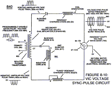
Voltage Sync-Pulse Gated Frequency (583 / 602a xxx 583 / 602n) (603/604a xxx 603/604n) of Figure (8-1) as to (605/606a xxx 605/606n) (607/608a xxx 6071608n) (609 / 611a xxx 609 / 611n) of Figure (8-2) … all, forming Voltage Pulse Burst Wave (619) as to Unipolar Pulse-Train (780A), Crossover Unipolar Pulse-Train (780B), and Clipped Unipolar Pulse Train (780C) as to Traveling Voltage Wave-Action (770) of Figure (8-1) of opposite voltage polarity (+/-) of equal Voltage-Pulse Amplitudes (+Vpp/- Vpp) are zero reference to electrical ground state (OV) by placing Amp Inhibitor Circuit (860) (Amp Inhibiting Coil 617, Blocking Diode 618, and Magnetic Induction Core 619) between electrical ground (OV) and Center Tap of Dual Bifilar Secondary Pickup Coils (616A/B) of VIC Matrix Circuit (690) of Figure (7-8) as to VIC Impedance Network Circuit (620) of Figure (7-1) , as illustrated in (840) of Figure (8-10). By doing so, Balance Phasing of opposite voltage intensity (+Vpp / – Vpp) is accomplished without experiencing current influxing caused by differential variances where Negative Voltage Peak Potential (-Vpp) is less than Positive Voltage Peak Potential (+Vpp) or Vise Versa … allowing Inductor Resonant Choke Coils Electromagnetic Fields Intensity (+Z2 / -Z3) to be, in turn, free of Electromagnetic variances of intensity (Z2 – Z3). This non-voltage shift (Balance Phasing of opposite Voltage Potential) helps prevents atom displacement during “Snapping-Action” by which “Resonant Electrical Stress” of opposite electrical polarity (RU/RU’ – ST/ST’) is applied equally across Water Molecule (s) (85) to propagate either Static (585) or Dynamic (612) Electrical Charging Effect (s) at elevated Voltage Peak Potential (s). Amp Inhibiting Coil-Assembly (617) is made up of magnetic inductance Stainless Steel 430FIFR wire material wrapped around a closed-loop Induction Magnetic Core (619) which is a separate coil-unit (860) apart from VIC Coil Assembly (580) of Figure (6-1).Blocking Diode (618) functions as an “Electrical Isolator” that prevents electrical discharge of Dual Secondary Coil (616A / B) during applied Pulsing Operations (49a xxx 49n).
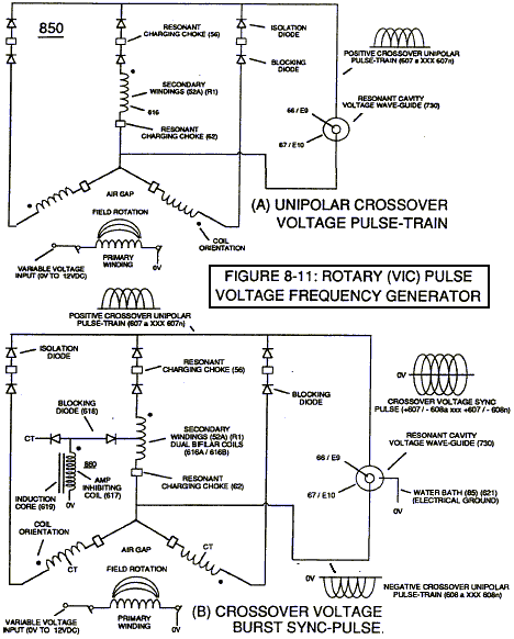
To ensure and maintain Capacitance Charging Effect (650) of Figure (7-4) across Water– Gap (Cp) of (7-8) during applied pulsing operations (49a xxx 49n), Crossover Voltage Wave-Form (780B) as to (780C) of Figure (8-2) is generally utilized by not allowing Convergent Point “Q” of Figure (780B) to reach Electrical Ground Point (OV) when each Unipolar Voltage Pulse (Vpp) is electrical energized in phase-distance relationship to cause the trailing edge (Vpb) of the first Voltage-Pulse (Vppl) to meet the uprising leading edge (Vpa) of the second Voltage Pulse Wave (Vpp2) at a distance above ground state (OV) determined by the Space-movement of the reforming Voltage Peak Wave (Vppa xxx Vppn) within Voltage Pulse Width (TI), as illustrated in Rotary Crossover Voltage Sync-Pulse Circuit (850) of Figure (8-11) where each VIC Pickup Coils (52A- 52B -52C) are axially spaced 120· apart to cause Convergent Point “Q” to be located 1/3 the height of Voltage Amplitude Peak Level (Vpp), as an example.
Resonant Cavity Configuration (s)
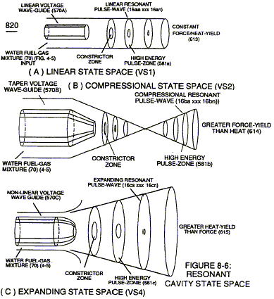
In reference to Resonant Cavity geometrical configuration to bring-on further response to Energy Vectoring (Ev)apart from Voltage Priming Stage (Vps) (applied incoming Voltage Pulse- Frequency 49a xxx 49n), Resonant Cavity (730) physical design parameter (s) is/are, now, taken into account in determining flame-heat projection (16), as illustrated in (70) of Figure (4-5) as to (590) of Figure (6-2): (A) Linear Cylindrical Resonant Cavity; (B) Taper Cylindrical Resonant Cavity; and (C) Non-Linear Cylindrical Resonant Cavity, as illustrated in (730) of Figure (7-12).
Linear Cylindrical Resonant Cavity (730A) Static Variable Condition (Svc) (790) of Figure (8-3) allows Flame-Front (VS1» of Figure (8-7) to be of equal magnitude when thermal explosive energyyield (gtnt) is compared with thermal heat-energy (Teh) since Electrical Stress Factor (RR’-SS’ as to RU/RU’ – ST/ST’) is constant with Static Gas Pressure (Sgp), as illustrated in Energy Vector graph (830) of Figure (8-7). Dynamic Variable (800) of Figure (8-4) produces Flame Front (VS3) when Dynamic Electrical Stress (RR’ – SS’ as to RU/RU’ – ST/ST’) and Dynamic Gas Pressure (Dgp) are both increasing in magnitude by the use of Taper Cylindrical Resonant Cavity (730B) of Figure (7- 12), as further indicated in Energy Vector graph (830) of Figure (8-7) under the titled-line “Progressional State Space” (VS3). Combinatorial Variable exists when Dynamic Voltage Pulse Wave (600) of Figure (6-3) is utilized with Linear Cylindrical Resonant Cavity (730A) of Figure (7- 12), as illustrated in performance graph (810) of Figure (8-5). Greater Heat-yield of Flame Front (16) is realized when Non-Linear Cylindrical Resonant Cavity (730C) of Figure (7-12) is used in conjunction with Differential Dynamic Variables (820) of Figure (8-6) where Dynamic Electrical Stress (RR’ – SS’ as to RU/RU’ – STIST’) is increased while the resultant gas pressure is allow to drop during the gas ignition stage (E9d) of Figure (6-3) as to Figure (590) of Figure (6-2), as finally noted by Energy Vector Graph (830) of Figure (8-7) under titled-line “Expanding State Space” (VS4).
Application of Usage
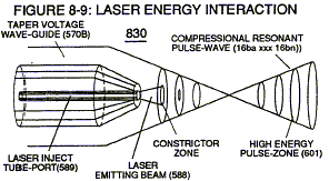
By simply intermixing /mterchanging any applied Electrical Voltage Pulse-State with any Gas Pressure State as herein described above can result in a predetermined hydrogen Gas Flame- Front that can be utilized for a particular application of usage. For example, Taper Resonant Cavity (590) of Figure (6-2) as to (820B) of Figure (8-6) is ideally suited for internal combustion I. C. engines as well as Rocket Engines where high thrust-yield of explosive power (gtnt) (582B) is required; whereas, Expanding Resonant Cavity (730C) of Figure (7-12) as to (820C) of Figure (86) is best suited for Furnace Applications. Linear Resonant Cavity (730A) of Figure (7-12) as to Figure (820A) is for Cutting-Torch applications (582) … to mention a few. In each and all Flame-Front (582A,B,C,) Resonant Pulse Waves are produced to net higher energy:-yield beyond normal gas burning levels. Laser Energy (588) being injected into Resonant Pulse Waves (16) by way of Laser Inject Tube-Port (589) helps maintain Plasma-temperatures at extremely elevated temperatures over the prior art.

