http://users.skynet.be/fa272699/Energie/Meyer/memos/section2.pdf
WATER FUEL CELL
Quenching Circuit Technology ; Rendering Hydrogen Safer Than Natural Gas
The Quenching Circuit Technology is a combination and integration of several Gas-Processes that uses noncombustible gases to render hydrogen safer than Natural Gas.
The, « Non-Burnable » gases are used to adjust hydrogen « Burn-Rate » to Fuel-Gas burning levels … recyc1ed to stabilize Gas-Flame temperatures .. .intermixed to sustain and maintain an hydrogen Gas-Flame … and used to prevent Spark-Ignition of supply gases.
The utilization and recycling of the non-combustible gases allows the Water Fuel Cell to become a Retrofit Energy System.
The Quenching Circuit Technology is systematically activated and performed in the following way:
Operational Parameters
Spark-Ignition Tube
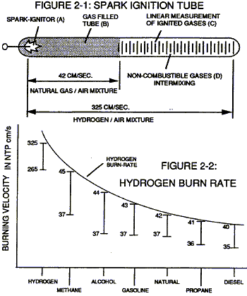
Spark-Ignition Tube (B) is a tubular test apparatus (1/8 diameter) that determines and measures the « Bum-Rate » of different types of Burnable Gases intermixed with Ambient Air, as illustrated in Figure (2-1).
Spark-Ignitor (A) causes and starts the Burnable Gas-Mixture (B) to undergo Gas-Ignition which, in turns, supports and allows Gas Combustion to take place … forming and sustaining a Gas-Flame. The expanding and moving Gas-Flame travels (away from spark-ignitor) the linear length of the gas filled tube (C) and is « detected » and « measured » (length between spark-ignitor and light-detector) in one second after gas-ignition. The Gas-Ignition Process, now, establishes the « Burn-Rate » of a Burnable Gas-Mixture in centimetres per second (cm/sec.), as illustrated in Figure (2-2).
Different types of « Burnable » Gas-Mixtures exposed to the Gas-Ignition Process were tested, measured, recorded and systematically arranged as to cm/sec. length, see vertical bar Graph (2-2) again. The Gas-Ignition Process was performed several times to establish the « average » Burn-Rate of the Fuel-Gases which, in turn, establishes the length of the vertical bars.
Gas Injection Process
Injecting and intermixing a Non-Combustible Gas (D) (non-burnable gas) with the ‘Burnable » Gas-Mixture (B) « changes » or « alters » the gas-mixture « Burn-Rate ». Increasing the volume-amount of Non-Combustible Gas (D) diminishes and/or lowers the « Burn-Rate » of the Gas-Mixture (B/D) still further. Progressive and controlled intermixing of the non-combustible gases (B/D) allowed the « Burn- Rate » of Hydrogen to be « lowered » or « adjusted » to « match » or … equal » the « Bum-Rate » of other Fuel-Gases, see curve line in Figure (2-2).
In terms of operational performance, the Non-Burnable gas (D) does « Not » support the Ji5 Combustion Process since the Non-Burnable Gas (D) « restricts » or « retards » the speed at which the Oxygen Atom unites with Hydrogen Atoms to cause Gas Combustion. The « Gas Retarding Process » is, of course, applicable to any type or combination of Burnable Gases or Burnable gas-mixture.
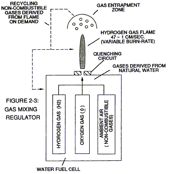
Gas Mixing Regulator Inherently, the Water Fuel Cell allows the « Burn-Rate » of Hydrogen to be « Changed » or « adjusted » from 325 cm/sec. to 42 cm/sec. (Co-equalling Natural Gas Burning levels) since Non-Combustible Gases (such as Nitrogen, Argon, and other non-burnable gases) derived from Ambient Air dissolved in natural water performs the Gas Retarding Process … sustaining and maintaining an Open-Air Flame beyond 5000-degrees F, as illustrated in Figure (2-3)
Natural water acts and performs as a « Gas-Mixing Regulator » when the Fuel-Cell is electrically energized by way of voltage stimulation (Electrical Polarization Process) …. producing a uniform gas-mixture (B/D) regardless of the Gas Flow-Rate of the Fuel-Cell producing a uniform gas-mixture (B/D) only when needed. In quiescent-state, the supply of gases (BID) being released from the water bath is « terminated » and « stopped » when the Fuel-Cell becomes « deenergized ».
The unused water, of course, remains as a non-burnable liquid. The gases (B/D) above the water bath is « vented » for safety purposes.
Flame Temperature Adjustment
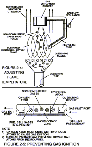
By capturing and recycling the expelled non-combustible gas (D) (derived from and supplied by the water bath) back into the sustained hydrogen gas-flame or Fuel-Cell causes the gasflame temperature to be « changed » or « altered » by way of the Gas Retarding Process, as illustrated in Figure (2-4) as to Figure (2-3). The recycling gases (D) controlled by an Gas Flow Regulator allows the gas flame-temperature to be « adjusted » or « calibrated » to any gas burning level (S), as so illustrated in Figure (2-2).
The « newly » formed and established gas flame-temperature remains constant regardless of the gas flow-rate of the Fuel-Cell. Continual feedback of non-combustible gases (D) is, hereinafter, called « The Gas Combustion Stabilization Process ». Automatically, the Gas Combustion Stabilization Process changes the « Burn-Rate » of the Fuel Cell gases (B/D) when obtaining the desired gas-flame temperature.
Quenching Circuit
Spark-Ignition of the Fuel-Cell gases (B/D) is prevented when the « Gas Retarding Process » is used in conjunction with a « Quenching Circuit », as illustrated in Figure (2-3), (2-4), (2-5) and 26).
The non-combustible gases (D) separates and prevents the hydrogen atoms to unite with oxygen atoms to « bring-on » or « initiate » Gas-Ignition. The narrow passaway (at least 1/8 inch long and having a .015 diameter) prevents the moving gas atoms from « Re-Grouping ». The alignment of the Fuel-Cell gases (BID) inside the tubular-passaway is, hereinafter, called « The Quenching Circuit ». The Quenching Circuit « Anti-Spark technique » is « independent » of both Gas-Velocity and Gas-Pressure.
Quenching Nozzle
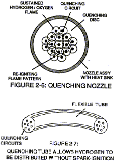
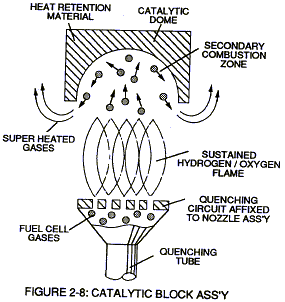
Additional Quenching Circuits arranged in a Disc-shape configuration forms a « Quenching Nozzle » when attached to an « Quenching Tube », as illustrated in Figure (2-4) as to Figure (2-6). The Multi Gas-Port Disc compensates for increased Gas-Velocity while « preventing » spark-ignition of the Fuel-Cell gases. The overlapping Flame-Pattern re-ignites the expelling hydrogen gas-mixture (B/D) should Flame-Out occur. Ceramic material is used to form the « Quenching Disc » to « prevent » hole-size enlargement due to gas-oxidation.
The non-combustible gases (D) keeps the Ceramic Material « cool-to-the-touch » by projecting the Gas-Flame beyond and away from the disc-surface … the Quenching Disc remains « cool » even if the Gas-Flame Temperature exceeds the melting-point of the disc-material.
Quenching Tube
The Quenching Disc is extended into a Flexible Tube to transport the Fuel-Cell gases safely over long distances, as illustrated in Figure (2-7). The Spark-Arresting Gas-Line is, hereinafter, called « The Quenching Tube. »
Catalytic Block Assembly
An Inverted hemispherical cavity placed on top of and in space relationship to the « Quenching Disc » insures total gas-combustion by recycling any « escaped » or « unused » burnable gases back into the gas-flame for Gas-Ignition … preventing Gas-Oxide formation, as illustrated in Figure (2-8) as to Figure (2-4).
Internal Combustion Engine
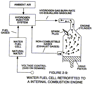
The Gas Combustion Stabilization Process (recycling non-combustible gases) is also applicable to operating an Internal Combustion Engine without changing Engine-Parts since the Gas Retarding Process allows the hydrogen « Burn-Rate to « equal » the « Burn-Rate » of Gasoline or Diesel-Fuel, as illustrated in Figure (2-2). The engine provides its own non-combustible gases derived from Ambient Air undergoing the gas-combustion process. Engine temperature remains the same since The Gas Stabilization Process is used.
Gas Grid System
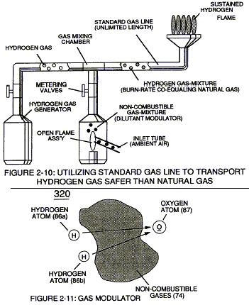
Ambient Air is the prime source of Non-Combustible Gases when the Air-Gases are exposed to and passes through an Open-Air Flame, as illustrated in Figure (2-10). The Gas Combustion Process of the Gas-Flame eliminates oxygen and burnable gas atoms from the expelling gases … producing an endless supply of non-combustible gases.
Mixing the « processed » Air-Gases with an Hydrogen Supply Source sets up The Gas Retarding Process … allowing the Hydrogen Gas-Mixture to be transported safely through existing Gas-Grid System.
Operational Parameters
The utilization and recycling of non-combustible gases, now, renders hydrogen gas as safe as Natural Gas or any other Fuel-Gas … allowing the Water Fuel Cell to become a Retrofit Energy System.