Lindemann, Peter, Attraction Motor 2
(page created for November 2007 update)
Peter Lindemann posts on Energetic Forum about the Attraction Motor Concept
From http://www.energeticforum.com/renewable-energy/271-electric-motor-secrets.html
Page 4 of the thread
# 91 ; by Peter Lindemann, Senior Member, 05-17-2007, 01:10 PM ;Passive vs Active Rotor
Quote: Originally Posted by Drexel : Dear Dr. Lindemann. Thank you for the clear explanation, now the “missing” Lenz effects make sense. To approach this problem from an energy viewpoint, the iron rotor piece requires no energy from the coil via transformer action so no energy is needed from the coil, except for the small losses induced in the iron rotor caused by eddy currents. It also appears that the eddy losses in iron may be the small Lenz effect you discussed – is this correct?
Taking this a step further, what if the passive iron rotor piece was replaced by a permanent magnet? This change now seems to make things much more complicated. With the right polarities the approaching attraction part should be enhanced, but now the leaving magnetic fields are going to want to induce currents into the coil to oppose the motor action. If the coil circuit is opened at that point then very high voltages should result. Does this make sense?
End of quote.
Drexel, I am glad to see you thinking this through. OK, the motor designs I am suggesting have a passive iron rotor. This allows these motors to operate with No Back EMF and gain in efficiency because they do not create any forces or fields that buck or resist themselves. There is ONLY ONE magnetic field in the system, the field of the stator coils, and they passively attract the rotor while turning on and off.
The moment you introduce a permanent magnet in the rotor, now you have TWO MAGNETIC FIELDS in the system. These two fields can and do interact with each other. These interactions invariably cause cross inductions, leading to the Back EMF problems the passive iron rotor avoids.
The small Lenz Law forces that appear in the stator coils account for the “rise time” and the “collapse time” of the magnetic fields produced by turning the current On and OFF. The movement of the iron rotor changes the inductance of the coil/core and therefore also affects the rise time and collapse time of the magnetic fields. But these changes are small, when compared to the losses produced by Back EMF.
Perhaps you should just run a few experiments on your own so you can see what happens. Thinking about these things can only get you so far. At some point, you must “see for yourself.”
# 94 ; by Peter Lindemann, Senior Member, 05-23-2007, 03:58 AM ;Slowly getting it…
Quote: Originally Posted by sykavy : Hi Peter. I watched your DVD again. Now maybe I understand better. But i’ll try and explain what I think I understood.
Id like to focus on Teals set-up.
I understand the most torque from the magnetic attraction means the iron needs to be very close. Why then is there a iron lip on the top of the coil. I still don’t understand that. Also could the spool for the coil be wrapped around a copper pipe or does it need to be plastic?
End of quote.
Sykavy. Thanks for your questions.The purpose of the “iron lip” on the top, inside of the coil is to close the magnetic field HALF WAY through the stroke. This allows the power stroke (point of strongest attraction) to coincide with the mid-point on the crank shaft (point of greatest tangential force). This arrangement allows the motor to produce the highest amount of mechanical energy for the least amount of electrical input.
The drawings I have used in the DVD are not the only configuration that will work to create this set of conditions. Its only meant to illustrate the point. If the coil is wrapped on a copper pipe, the copper will act as a “shorted turn” one loop secondary coil and create Back EMF against the power coil when it turns ON and OFF. This will dramatically slow down the rise-time and decay-time of the power pulse in the coil. Since rapid rise-time and decay-time is advantageous for higher RPMs of the motor, using copper pipe like this inside the coil is not recommended.
# 96 ; by Peter Lindemann, Senior Member, 05-25-2007, 10:06 AM ; For the Last Time!
Quote: Originally Posted by kenny_PPM : Peter, with all respect , isn’t this method, i Should say, working model, a flynn PPT motor (without any permanent magnets of course) with Bedini circuit recovering the collapsing field??
If it is more than that please reply, as I am going to water jet cut laminates within .005 thousandth air gap to rotor and build a flynn (4x force)with the recovery circuit of bedini as you also have posted and if I can add to that efficiency I would be all ears! Ken
End of quote.
Dear Kenny. The method and principles of building an electric motor with No Back EMF is MY DESIGN. I built my first working model in 1983. It could recover 80% of the electrical energy and produce high torque. This was before I ever met John Bedini. These motors produce mechanical energy at a much higher rate than any other method I know of, including Faraday’s direct induction, Flynn, Bedini, or anybody. Recovery of the collapsing field is a bonus, but it is NOT NECESSARY for the mechanical energy gain.
I’m pretty sick of people like you, Kenny, (with all respect…sic) who haven’t bothered to study my information, while you are perfectly willing to listen to people who obviously don’t understand it. My system is NOT merely a Flynn/Bedini motor that I am stealing. None of these characterizations are true. In the last 25 years NOBODY has suggested doing what I am saying now. NOBODY!!!
Flynn’s system requires permanent magnets; mine doesn’t use any. Flynn’s system uses a combination of a permanent magnet field AND an electromagnetic field to produce a combined magnetic field with extra strength. If you think you are going to build a unit that combines this idea with John’s recovery circuit I published, what you are REALLY doing is just trying to build Bedini’s BUCK-BOOST motor from his first patent. This has NOTHING to do with what I am talking about! You haven’t even bothered to read all of the posts in this forum, where the distinctions are clearly defined.
Bedini’s Mono-Pole system recover 95% of its electrical energy but produces low torque because the magnetic fields are open. My system produces high torque and a recovery that is not suitable for battery charging because my magnetic fields are closed down all the way, so very little Radiant Energy is produced. Actually, my system doesn’t even need to recover the inductive collapse to produce energy, although it can be a bonus if it is engineered right.
If you want to learn about the benefits of building a No Back EMF motor, then buy my DVD and study the material. If not, just build your “Flynn” motor and do what you want. Peter
# 99 ; by Peter Lindemann, Senior Member, 05-25-2007, 12:52 PM ; Let’s Be Perfectly Clear…
Ken, Who invented Back EMF recovery? NOBODY! Joseph Henry invented the first electro-magnet, in 1821, using power from a battery running in a coil of wire. He was the first to see that when contact is broken, a big spark appears. Various researchers and scientists, since then, have studied this phenomena. Most people considered the effect a nuisance. Tesla was the first to suggest that there was a new form of energy in this discharge. Most people ignored him too. I credit John Bedini for working out how to use this energy to charge batteries. Scouring the historic record, nobody else figured out how to do that.
Bob Teal knew the energy was there to recover, but only figured out how to light light bulbs with it. This can be seen in the interview clips and the still photos of his motors. Even in my 1983 Flux Motor design, we had the energy recovery, but we never applied it to recharge a battery. Ed Gray was charging capacitors, dumping the charge into an inductor, getting the mechanical energy production, AND recovering the inductive collapse to charge another capacitor. Gray EXPLODED batteries trying to recover the energy, but never really figured that part out.
So, JOHN BEDINI is rightly credited with INVENTING the circuits and methods for safely and effectively using the energy of the inductive collapse to charge batteries. But NOBODY invented the inductive collapse. This is simply a process of nature. Every DC-to-DC converter uses the process to create a voltage rise, but there is no energy GAIN in this method. Even Rick has to covert some of the mechanical energy back to electrical to get the machine to self-run. So, the TRUTH is, the free energy in all of these machines shows up as MECHANICAL ENERGY! Nobody is claiming more that 95% electrical recovery in the Mono-Pole motors.
Also, I do not claim to have invented either the No Back EMF motor or the idea of attracting iron to an electromagnet. That would be preposterous, in the extreme. I do claim to have built working models of No Back EMF magnetic attraction motors in 1983. I do claim to UNDERSTAND the conditions that must be satisfied to maximize the production of mechanical energy in these motors, and I do claim to appreciate the benefits of using these methods over all others. That is what my DVD is about.
You have seen, in your own experiments, that the torque is there in the methods I am discussing. You have also said that you can produce 9x torque using a Flynn type design. So, the question is, HOW MUCH electricity does it take to create each effect? You don’t need MAX torque, you just need the max torque for the least electrical input. If you focus on this question, it will show YOU what direction YOUR research should take.
You want to build the “ultimate machine” and you want it to be the next one you build. DON’T WE ALL! The only thing you can do is build your next machine, based on the best knowledge you have at this time. That’s what we all do. John Bedini has THE LARGEST museum of machines that were built and tested of anyone that I know of. He found what he was looking for! I have also built and tested over 50 different experimental designs. I also found what I was looking for. John and I were looking for different things.
# 101 ; by Peter Lindemann, Senior Member, 05-26-2007, 02:38 AM
Ken. Sounds like you are well along in your research. I have looked for the “easiest, simplest, low-tech” method that works. Something that will run for years with no maintenance and just hum along in the closet. Something that can be built from junk, lying around, or fixed with a saw and a hammer…. and maybe a file and a screw driver too!
No sense knowing how to build a machine if it can’t keep your own lights on. Best wishes, Peter
# 102 ; by nali2001, Member, 05-28-2007, 05:40 AM ; To Lindemann
Hallo Peter and thanks for the reply regarding the old FLuxgate generator and your work on it. If you have the time and feel like it, please supply us with the data and info regarding that device.
Now you might already knew this one, but here is a very detailed and helpful patent which describes a means and method of building motors and generators which do not suffer from Back emf / or Lenz Law. Even more so the back emf is rendered so that is aids motor motion or generated output power. See it here:
or Motor and generator wherein magnetism aids motion – Google Patents http://www.google.com/patents?id=dboCAAAAEBAJ&dq=6169343
I know you have always been interested in Gray radiant energy stuff, well some old video’s have been surfacing lately. So helpfully people will show more interest in the old Gray stuff and related Tesla technology’s in the near future.
Here are some shots from the conversion tubes for example: http://home.planet.nl/~sintt000/Gray/Tube1.jpg
http://home.planet.nl/~sintt000/Gray/Tube2.jpg
http://home.planet.nl/~sintt000/Gray/Tube3.jpg
http://home.planet.nl/~sintt000/Gray/Tube4.jpg
http://home.planet.nl/~sintt000/Gray/MaybeTube5.jpg
http://home.planet.nl/~sintt000/Gray/TableSys.jpg
http://home.planet.nl/~sintt000/Gray/TableSys2.jpg
# 105 ; by Peter Lindemann, Senior Member, 05-30-2007, 11:18 AM ; No Load Generators…
Steven. Just so people are clear. A fair number of patents have issued in the last 20 years on No Back EMF motors and generators. But there are still a few of us around who were doing this more than 25 years ago, who never filed for patents. Both John Bedini and I had working systems that date from the early 1980’s, and John has some stuff that dates earlier than that.
The “free energy” community has been GROPING around for the last 20 years, looking for a simple ENERGY GAIN methodology. The No Back EMF methods ARE one such method that people, for the most part, are not aware of. Those of us who have known this, and known for DECADES, have been quiet about it, thinking some business opportunity might arise. I no longer believe the business opportunity will arise, so I am PUBLISHING what I know.
The designs and methods for producing No Back EMF Generators are much more complex than the Motor designs. This forum is to share information on the No Back EMF Motor designs to those who wish to learn. I am NOT interested in CHATTING or COMMENTING on dozens of semi-related ideas.
# 107 ; by Peter Lindemann, Senior Member, 06-01-2007, 12:37 PM ; Why not….
Quote: Originally Posted by Shad : Hi Peter. I have one question about the no-Back-EMF-Motor ; Would it be possible to run it like a electric coil-gun?
Below I give two websites on the basics on how coil-guns function, for those, who havent heard about it or might need more detailed info. You will see that it is very similar to the no-back-EMF-Motor.
Theory http://www.coilgun.eclipse.co.uk/coilgun_basics_1.html
Experiments – Thyristor Fired Coilgun http://www.coilgun.eclipse.co.uk/thyristor_fired_coilgun_experiments.html
The piston might need to be a bit shorter than what you show in one of your videos, so it can accelerate nicely in the coil and wont get stuck. These coil-guns produce tremendous powers. If now this projectile would work like a kind of air-spring it theoretically should make a nice motor?! The piston would compress the air together, with tremendous power, the compressed air acts like a spring and presses the piston back into its original position. Springs in common show a weird effect, physics can not really explain. If it discharges or releases the force a two to three times stronger force will result, which was invested in the compressing of the spring. Naudin made good experiments with springs one can see them on his website, with OU effects. This would give a nice interaction, and the invested energy would be recovered in this way.
But what occupies me much more is if the coils could not be directly fed with dielectricity and thereby built up a magnetic field in the coil, which after the collapse would invert into a dielectric field, which could be caught in a capacitor again.
Lighty and I in the past two years did experiments with positive and negative dielectric spikes and could observe very interesting effects in the coils. Although there almost was no current going into the coils a striking effect occurs on the magnetic fields and the magnet jumps under the influence of this force. On the other hand magnetic materials like iron or mu-metals react almost not at all, or the reaction is very weak.
If a magnetic projectile would be taken now, instead of an iron-piston one would need very little energy to run it. If I remember well, did the inventor Bob Teal use his invention for air compressors? Could it be he simply had an air-spring which could recover its energy?
End of quote.
Shad. The question you are asking is “can the magnetic attraction motor be run from capacitor discharges?” The answer is YES. Ben discussed doing just that in post #39 in this forum. You can see in the schematic of your coilgun that the energy of the inductive collapse is thrown away with the shorting diode 1N5402. It would be simple to divert this into a second capacitor to conserve the majority of this charge for the next shot. With a 10ms discharge, a very high percentage of the energy could be recovered for another use.
Ed Gray was doing what you suggest with the dielectric discharges. He was able to repel plastic projectiles with extremely high force using dielectric discharges. He claimed he could launch a plastic projectile with a million amps and accelerate it to 88,000 feet per second in under 0.001 second. So, YES, your ideas are correct.
As for the air compressor part of Teal’s second patent, it looks like an attempt by his patent attorney to toss in another application. None of the pictures, videos or other company literature ever shows or mentions the air compressor feature. Building an electric motor with high torque and low electricity consumption was the primary purpose of the design, as far as I can tell.
# 112 ; by Peter Lindemann, Senior Member, 06-18-2007, 08:15 AM ; See for yourself….
Everybody. With the help of a friend, I have built a Rotary Attraction Motor from a Series Wound DC motor. All of the windings have been removed from the rotor and the iron sections shaved off to produce more of a “bar rotor” shape. Aaron came by last week and made a video of the motor that will be posted soon. He will also post the schematic, pictures of the rotor modifications, and pictures of the whole set up.
For those of you who have been “waiting and wondering”, I hope this helps you focus your interest in this line of research. Please wait for Aaron to post these new materials before asking any questions. Thank you.
Please visit this link for the the following video Lindemann Rotary Attraction Motor http://www.esmhome.org/library/bob-teal/index.html
(MDG nov07: Or see the first page on Dr. Lindemann)
# 115 ; by Aaron, Energetic Scientist, 06-18-2007, 04:09 PM ; power output
Hi Gyula, Peter will give you the more technical answer on this but what I understand is that the motor you you see has the same gap as an unmodified one. With a larger gap like this, there is a lot less power. I don’t think it is practical to close the gap by adding anything to the rotor, etc… but a rotor can be made so that the gap is smaller if made that way from the beginning.
Peter was explaining to me about the concept of the math of the increase in the power by decreasing the gap. I don’t understand the numbers but I’m very excited to see one of these that has a rotor made to have a very, very, very small gap. If the current rotor had a gap 2/3 smaller, the power could be 3 times as much for the exact same input. That comparison may not be accurate but that is the concept anyway.
# 118 ; by Peter Lindemann, Senior Member, 06-19-2007, 12:36 PM ; Re: Some more measurement data
Dear Gyula. This motor has both advantages and disadvantages. It represents an experiment to see if an off-the-shelf motor can be converted to run on the attraction motor principles. The answer is, it can. This motor was made WITHOUT any machine tools, like a lathe or a mill. This makes this model well within the realm of many backyard experimenters to build and learn its principles of operation from. That is the advantage.
The disadvantage is that it carries forward all of the inherent design characteristics of the motor it was made from. It happened that this motor was handy for the first experiment of this kind. It had an air-gap of .021 inches, and was wound for 115 volt AC or DC operation. It is rated at 1/4th horse power, and probably has an efficiency of about 75% (not measured by me).
In its unmodified form, this style of induction motor produces torque by the current running in the rotor windings as they intersect the stator’s magnetic field. The gap is made larger in these commercial motors so as the bearings wear out, the motor will continue to run without the rotor hitting the side of the stator. These motors are designed for longevity of operation, NOT for high efficiency.
The purpose of posting the movie and pictures is NOT to prove to you all that you can make a “free energy” motor out of this. It is to demonstrate that the principles of the rotary attraction motor are universal and can be made from a variety of motor geometries.
This motor demonstrates all of the principles I discuss in the DVD, so you can see them with your own eyes. But, the torque is not maximum because the gap can still be closer, and the electrical recovery is not maximum because the ON time is longer than it takes to magnetize the iron in the stator. If you understand what this means, then you are learning something. If you want everything shown to you on a Silver Platter, then you have to wait longer.
Measurements of the torque on this model have been a challenge. All I have is the aluminum pulley to work with. I made 4 different leather straps to make the dynomometer braking mechanism with, and each one grabbed the curved, inside edge of the pulley violently at a certain point and made the process very dangerous. I then tried a piece of nylon rope, which worked OK, but it also stretched, so all of the deflection was not on the spring scales. This made the reading of the torque artificially lower by some unknown amount. Even so, the initial torque measurement for this decidedly flawed set-up was 22% efficiency for the mechanical energy created and about 20% electrical recovery. Considering the very simple circuit running it and the off-the-shelf nature of the physical geometry, NOT BAD. It shows that torque can be produced, with room for improvement by making the air-gap smaller, and that electricity can be recovered, with lots of room for improvement, by timing the impulses appropriately.
Obviously, there is no “free energy” being demonstrated. But that wasn’t the point of showing it. All I am trying to convey is that there is another motoring principle here that works, that is different than direct induction (Faraday), the Bedini SG method, or switched reluctance. Each of these motoring principles has advantages and disadvantages.
So, if you find a commercial motor with a close gap to start with, and apply the principles to maximize the electrical recovery, there is no reason a motor with 80-90% mechanical efficiency can’t be made that also practices 80-90% electrical recovery. With some simple circuits, the recovered electricity can be put back on the front of the circuit, so (worst case scenario) an 80% mechancial energy production can be produced for a 20% input (100% – 80% = 20%). That is a COP of 4.
I hope this extra detail helps you understand, not only what this model is doing, but also what is still possible as improvements.
Page 5
# 122 ; by Peter Lindemann, Senior Member, 06-20-2007, 12:02 AM ; System Suggestions
Steven. Thanks for reviewing the latest materials. Especially, thanks for thinking about how to improve the processes.
When using the left-over rotor from a modified series motor, the rotor iron ends up having slots in it. I believe this introduces unwanted and unnecessary inefficiencies in the magnetic attraction process, by breaking up one, continuous attraction into a number of smaller attractions. Adding extra slots to the stator pole faces, I think, only makes this situation more complicated. You can see that the effect of your suggestion is to ADD more AIR space to the rotor/stator interface zone. Since it is generally agreed that the air-gap introduces inefficiencies, and that the optimum design would use the smallest practicable air-gap, I predict that your suggestion may not produce the benefit you anticipate.
I believe that a new, solid core rotor piece facing the solid core stator piece will give better results. But, that is my opinion. Like I said, I’m glad to see you thinking about this. You should try your adaptation, and see what it does. The experimental results are the truth.
Another possible solution is to break up the input ON time into a series of shorter pulses, based on the rise-time of the inductor. I believe this will produce a more beneficial effect by maximizing the electrical recovery and by maximizing the amount of the motor torque produced by the electrical recovery. This is the new motoring principle I describe at the end of the DVD. The new motor movie clearly shows that the motor works on less input when the electrical recovery produces its share of the motor torque.
Each different stator/rotor arrangement will have adaptations of the principles that maximize its operations. Thanks for suggesting that people can find this type of iron lamination stator core from old washing machine motors. This gives home experimenters another possible starting point from which to begin. Thanks!
# 123 ; nali2001, Member, 06-20-2007, 12:32 AM ; Idea
Yeah pulsing the same coil multiple times with the same rotor as you drew in the picture might indeed also have good results.
Anyway I got the idea from this page: Waveform Optimization http://www.me.berkeley.edu/PREM/waveform.htm
# 126 ; by Peter Lindemann, Senior Member, 06-20-2007, 09:57 AM ; Good idea
Lighty. Your idea of using an 8-bit logic chip to control the circuit can definitely work. This is for advanced engineers and is beyond most backyard experimenters. I am researching various approaches. I am also looking at going in the other direction and modifying the brush commutator to run the motor. That way, only a diode to channel the kick back would need to be added.
I’m not sure setting an efficiency benchmark to build from with the current modified motor is useful. It has too many built-in design features that reduce the efficiency. This was just a first test to see if a series wound motor could be modified to produce a rotary attraction motor. For those of us who are working on this project, it proved that further work on this idea is worthwhile. We have already identified an other, larger series motor that has a much tighter air-gap. More extensive modification will be made to this second motor, to try to make up for more of its deficiencies. I have shared what we have done so far. That’s all.
# 128 ; by Peter Lindemann, Senior Member, 07-09-2007, 11:47 PM ; I’ve told you everything, already…
Dear Forum Members, I assume many of you have seen the news that the Steorn Magnet Motor public demonstration failed to work. It is my personal opinion that this demonstration was probably interfered with somehow, since it worked for 4 hours the day before, and then developed “friction” problems in the display case. They have had multiple working models for years, having asked over 100 Universities to test them in private.
As I have stated in my public writings for years, I do not believe the authorities will allow an unequivocal demonstration of a fuel-less power plant in the foreseeable future. If you want one, you are going to have to learn how to think, build models, test them, and share quietly with your friends.
I have told you everything you need to know about how to build an electric motor that can produce 80% mechanical energy and return 80% of its input electrical power. That is enough to build an electric motor with a COP = 4. The probability of me being able to SHOW you anything more is low.
I encourage all of you who have been waiting to see a finished model to start experimenting. Print out everything I have posted in this Forum and study it until you understand it. Then build a model. Best wishes, Peter
# 137 ; by Peter Lindemann, Senior Member, 08-06-2007, 01:13 PM ; Recommended Air-Gap
Quote: Originally Posted by nali2001 ; Hello Peter. I was wondering, what airgap size would be a good value in your opinion. Im asking this because you (as I remember correctly) said the airgap in your demo motor was too large, well here we use cm and mm so when you said it had a 0.021 inch gap I never took the trouble to convert it to mm to get a better sense of size. Well I just did a conversion and I was kind of surprised that you call a 0.021 inch or 0.53mm gap too large. I mean in my opinion it is pretty small already. I remember from my fluxgate Ecklin generators (sorry for that) that getting super tiny air gaps is a real pain and so I was kind surprised that 0.021 inch would not cut it. I understand it depends on the actual rotor size but what would you thing to be a good size? It cant be to tiny since we need to consider bearing wear and metal expansion due to Eddy Current heating and such.
End of quote.
Dear Steven, Yes, getting the air-gap small is a “pain”, but that is what is required for high mechanical power production. The Flux-Motor I built in 1983 had air-gaps of .002″ per gap, for a total air-gap of .004″. This is one-fifth the air-gap of the demo unit shown in the YouTube clip. If that unit was up-graded with an air-gap of .004″ (instead of .021″) the mechanical power produced would be more that 4 times greater for the same electrical energy input.
I measured the mechanical power output of the demo motor at about 23%, so increasing that by 4 times brings it into the 90% mechanical energy range that I have said would be there. Look at the air-gaps practiced in the Switched Reluctance Motors. You’ll see they are very small when the motor is rated at 94% efficiency. Peter
# 138 ; by Peter Lindemann, Senior Member, 08-06-2007, 01:36 PM ; Reflections on Criticism
Dear Grace, Thank you for your support. You understand me pretty well. But I do have feelings and people’s critical comments do bother me. There has not been ANY scientific criticism of the information. That is, no one with an educational background in electric motors has refuted any of the information I present.
Periodically, I do receive supportive comments. The following is a clip taken from the kind of emails I get privately:
“The quality of the material in the book was high enough that I ordered two of your DVDs, which arrived yesterday. I am rather ashamed to admit that I was not expecting much from the secrets of electric motors. Electric motors are everywhere. We know a lot about them, after all.
I finished learning about the secrets of electric motors on the stroke of midnight last night. I understood every word you said. At the end, I was STUNNED. STUPEFIED! I literally felt faint. I just sat in my chair in the living room and stared at the black television screen, thinking, “How could we ALL have missed that, all these years? Are we really that blind and stupid?” I know that I certainly felt that way. Needless to say, I didn’t sleep well last night.
I have a PhD in mechanical engineering – specializing in control theory – from the University of Missouri in Columbia. I got my bachelor’s degree in 1979, worked awhile in a power plant, went back to school, and got the PhD in 2002. You and I are maybe the same age. I attended the electric motor labs in college where we learned about back EMF. I was around large generators for years. Certainly, the existence of back EMF bugged me, and I remember wondering why we couldn’t get rid of it. Then, in graduate school, I encountered back EMF again when developing control strategies involving induction motors. I never tried to figure out how to get rid of back EMF because there were so many engineers who are smarter than me, designing motors. If it could be done, they would have done it.”
(I continue to correspond with this person but I have not received his permission to post his comments here, so I am withholding his name.)
The real project is to “light up” one mind at a time. Thank you for your understanding and your support. Best wishes, Peter
# 141 ; by Peter Lindemann, Senior Member, 08-08-2007, 12:41 PM ; Thank You
Sykavy, Thank you. It means a lot to me that you care enough to apologize publicly. This shows a high degree of “civility” operating within you, and I would like to acknowledge this. You are on the right track.
Free Energy will power some future civilization where people voluntarily restrain themselves from inappropriate actions that may hurt others. War will have been outlawed and dishonesty will be out of fashion. That machines will power themselves will seem secondary to the more important truth that people will want to live together in peace and cooperation.
Caring for others, speaking your truth, and living in integrity is the beginning of this future. When God’s generosity pours spontaneously through your open heart, you will know the secret of Free Energy. Its not about the machines. Peter
# 143 ; by Peter Lindemann, Senior Member, 08-12-2007, 11:31 PM ; Excellent place to start..
Quote: Originally Posted by nali2001 ; Dear Peter, Thanks for the reply. I must say I respect you and your machinist for achieving that kind of accuracy.
I mean I have an industrial Lathe and Mill. But making a system from scratch even with these tools is not so easy. I mean even machining the center shaft will be hard since once you have done one side you need to take it out of the chuck and machine the other side. And you never get it within absolute accuracy again. And then to note that I am talking about a solid steel rotor . Making the rotor out of laminations is even a difficulty step further.
In my opinion for the sake of this project it should be a good choice to find somewhere a second hand variable/switched reluctance motor, and if necessary re-wind the thing and apply back emf recovery. You will get everything in one package that way. A good stator and an accurate rotor made out of laminates. Ok you might need to replace the bearings but other than that, buying a second hand reluctance motor will be the best, and possible cheapest solution.
Maybe there is a second hand system floating around on Ebay? Or maybe some members here know an area in the industry where this type of motor are often used so we know where to look for them? I think they were used in some exotic car alternators as well, but Im not sure.
End of quote.
Dear Steven, Yes, I think your idea of starting with a switched reluctance motor frame is an excellent choice. In conversations with another researcher, this idea came up as well. He believed that by modifying the power supply pulse timing, the motor could be brought into the proper operating window. I think ALL of these things need to be tried.
This is why I published the material I had. I am very happy that other researchers, such as yourself, are now adding important ideas to this project. Together, we can make this happen. Keep up the great work!
# 150 ; by Peter Lindemann, Senior Member, 08-20-2007, 11:23 AM ; Relationship of Air-gap to Power
Dear Sykavy, You asked “Could the gap be wider if we made a stronger electro-magnetic pulse?” Yes, in the motors I have now, the gap is wider. The motor still runs but is weaker. Making the magnetic field stronger makes the motor run faster and stronger, but also draws more electricity to accomplish this.
The purpose of making the air-gap smaller is to make the motor run faster and stronger WITHOUT drawing more electricity to do it. This makes the production of mechanical energy MORE EFFICIENT.
I hope this helps you understand the relationship between the power of the motor, the air-gap, and the efficiency of mechanical energy production better. Peter
Page 6
# 152 ; nali2001, Member, 08-21-2007, 01:57 AM
Some old variable reluctance ‘Ecklin’ info.
– http://www.rexresearch.com/ecklin/ecklin9.jpg
– http://www.rexresearch.com/ecklin/ecklin7.jpg
– http://www.rexresearch.com/ecklin/hyperv1.jpg
– http://www.rexresearch.com/ecklin/hyperv2.jpg
– http://www.rexresearch.com/ecklin/hyperv3.jpg
– http://www.rexresearch.com/ecklin/garrett1.jpg
– http://www.rexresearch.com/ecklin/garrett2.jpg
– http://www.rexresearch.com/ecklin/ecklin1.jpg
– http://www.rexresearch.com/ecklin/ecklin2.jpg
– http://www.rexresearch.com/ecklin/ecklin3.jpg
– http://www.rexresearch.com/ecklin/ecklin4.jpg
– http://www.rexresearch.com/ecklin/ecklin5.jpg
– http://www.rexresearch.com/ecklin/ecklin6.jpg
– http://www.rexresearch.com/ecklin/ecklin8.jpg
– http://www.rexresearch.com/ecklin/ecklin10.jpg
– http://www.rexresearch.com/ecklin/ecklin11.jpg
Other permanent magnet reluctance machine
– http://home.planet.nl/~sintt000/Gen/002.jpg
– http://home.planet.nl/~sintt000/Gen/003.jpg
– http://home.planet.nl/~sintt000/Gen/001.jpg
# 154 ; by Peter Lindemann, Senior Member, 08-21-2007, 02:57 AM ; Ecklin designs and more…
Steven, Thanks for putting these links up for people to study. The problem with most of the Ecklin designs is that they DON’T work the way Ecklin imagined they would. He was primarily a theorist, not a model maker. He did NOT test most of these designs. During this period, I was working with Bruce DePalma and Michael Knox in Santa Barbara, California. Either Michael Knox and I or someone else in Bruce’s larger circle tried every one of these designs. Many of them, especially the ones with the AC coil and the DC coil on the same piece of iron, don’t work! The DC field is too strong in the local area and even opening and closing the gap with the rotating iron piece causes almost NO FLUX CHANGE in the AC coil. In some cases, special changes had to be made to the circuits to make them work at all. But then it wasn’t an Ecklin design anymore.
The second set of designs you posted are much better, but they too have loading sensitivities. If you put a simple resistive load on the output of these generators, they experience much of the same back EMF drags as a standard generator. Lenz Law is tricky to side step, but it can be done. If you diode block the electricity generation on the magnetizing cycle and only draw power out of the coil during the field collapse, the system works better. With other minor modifications, the performance of this style of generator can be excellent.
Its good for some of the newbies in the group to understand that the ideas I am presenting are well established in the literature, and people have been working on solving these efficiency issues for decades.
Thanks again for the links. This is the material people should be thinking about and experimenting with if the cost of electricity is to be reduced to a tenth of its current cost. Peter
# 155 ; nali2001, Member, 08-21-2007, 06:24 AM ; Ecklin’s real work
Thanks for the reply Peter, I have always wondered if Ecklin actually build/test ‘his’ devices.
I mean look at this one:
As you can see half down this page, the EBM machine uses also a reluctance switching principle.
Leslie Szabo, Energy by Motion, over-unity, free energy generator http://www.rexresearch.com/szabo/szabo.htm
http://www.rexresearch.com/szabo/wo9213.jpg
EBM (Energy By Motion) machine http://video.google.nl/videoplay?docid=-314404128614949275&q=ebm&total=2182&start=0&num=10&so=0&type=search&plindex=2
# 159 ; nali2001, Member, 08-22-2007, 08:39 PM ; Air gaps
Well Sykavy, small air gaps are indeed much desired. But if you go too crazy with them they can in my opinion become problematic. When you want to get in the range of like 0.02mm you really stet the bat pretty high for yourself. Everything must be machined with top notch precision, and also you must start to think about what the eventual bearing wear will be doing, also metal expansion due to to heating will become considerable. Stator vibration and stretching will also now be an issue.
Now there is another way to combat the need for insane small air gaps. And that is to increase the ‘contact’ or ‘pole’ surface. The longer the total pole the more interaction surface you have.
Just look at this render and see the small pole surface: Infolytica » Gallery » TEAM problem 24 – Nonlinear Time-Transient Rotational Test Rig http://www.infolytica.com/cn/coolstuff/ex0076/
Now compare that with the stator of a real use reluctance motor: http://www.eti.uni-karlsruhe.de/wolfju/pictures/Laufer.jpg
# 161 ; nali2001, Member, 08-23-2007, 10:44 PM ; Designs
Hi Sykavy, Well I don’t really know if the solenoid piston design has significant advantages over the ‘normal’ switched reluctance motor design. On the one hand one might think there is better flux interactions since the coil encapsulates the piston core. But on the other hand you must have some support system to guide the piston, which results in noise, losses and wear.
There are so many different types of Reluctance motor design out there you wont’ believe. Here for example is an interesting addition:
http://www.jstage.jst.go.jp/article/ieejias/126/4/385/_pdf
Also another method for reducing the air gap size is having ‘slots’ in the stator and rotor core elements, so that the rotating parts kind of interlock or ‘mix’ with each other. Like this:
http://home.planet.nl/~sintt000/SlotRotor/1.jpg
http://home.planet.nl/~sintt000/SlotRotor/2.jpg
http://home.planet.nl/~sintt000/SlotRotor/3.jpg
# 166 ; nali2001, Member, 08-25-2007, 05:31 AM
Hi Sykavy, Yes, making the slots and fingers will be quite a bit harder to make than just a flat surface rotor. But I think it has some big advantages since now the two poles are ‘virtually’ interlocking. So one might think that the need for the super small air gap will be reduced.
Iron filings have a permeability of next to nothing unless (professionally) pressed. So that would not be a real helpful solution in my opinion.
The main problem here is (as always) money… Like I said a factory where they make motor laminations will have no problem stamping out the laminations needed for a No-Back emf motor. But although I have no idea what it will cost to make such a core for you, I doubt that it is in reach of the ‘common man’. Maybe having them laser cut is more do able.
# 167 ; by Peter Lindemann, Senior Member, 08-25-2007, 10:58 AM ; You’ve got a Good Eye..
Quote: Originally Posted by adam ant ; hello all, This is my first official post and i thought this would be a good place to start. i just finished watching Mr. Lindemann’s DVD and i was very impressed. i studied motors and generators back in 1996 with the US Navy, but their courses are so packed together and in such a short time frame, that i only retained about 10% of that knowledge. after watching that DVD, and also reading these posts, i can say that im glad i lost that garbage “science”.
Mr. Lindemann, i must ask, in your DVD as you begin to mention Teals’ circuits for his patent, and mentioned that their is a battery hooked up. I wondered if you noticed that his schematic drawing of a battery is showing negative (-) facing OUT on both sides. (both + terminals are touching). Is this a typ-o on Mr Teals part, or is he trying to say something here?
End of quote.
Dear Adam (Ant), Yes, there is a error in Teal’s patent drawing concerning the correct nomenclature for a battery. In Figure 5 and Figure 8 in Patent #4,093,880 the batteries are drawn with only 5 plates. Since there are no transistors or diodes in the circuit, we don’t know which is the Positive (+) terminal, but I have always redrawn it with the Positive terminal up. In Figure 6 in Patent #4,024,421 the Negative terminal is clearly shown in the down position and going to the coil first, while the Positive terminal is shown going to the switch. I have always assumed the circuits in the second patent were essentially the same as in the first patent.
The function of the circuit does require a normal battery connection, and not a battery with two Negative terminals. This is definitely an error in the drawing, not a covert secret methodology.
# 168 ; by Peter Lindemann, Senior Member, 08-26-2007, 12:30 AM ; Pistons are Iron
Quote: Originally Posted by adam ant ; thank you Mr Lindemann for your explanation, you clarified this error for me.
another thing that i found, towards the end of the video you show the mechanical drawing of Teal’s motor.(showing the solenoid)
in that picture, there is component #76, im assuming is supposed to be the actual piston. however, there is a little white space in the center of this, a line at the top, and more white space at the top of piston drawing, which is probably supposed to be empty space.
in the actual photo, with the piston fully exposed, there is no hollow area to the piston head. could component #76 actually be an aluminum sleeve, and the white space is the iron?
earlier in this thread, someone mentioned that an aluminum disc hit with a hard electro-magnet spike will shoot it way up into the air.
i would imagine that as the coil energizes, the iron part of the piston would be drawn up into the coil, and when the armature reaches full extension, a huge spike violently repel the aluminum sleeve back out of the coil. this would give direct force to the piston travel both in AND out, virtually doubling your torque.(or more)
if i am way off, please forgive my ignorance, it has been years(12) since i last studied any of this. thank you for your previous answer. -adam ant (bryan)
End of quote.
Bryan, Thank you for using your real name. I appreciate that. To the best of my knowledge, the “white space” inside component #76 is AIR. The area defined by the cross-hatch pattern is the part #76 which is defined in the Patent body as the “core”. Its mounting to the connecting rod (#78) is screwed into the base of the core. The area above this is empty, or in reality, filled with air. The use of Aluminum is never mentioned in Teal’s patents.
These drawings are “symbolic” in many ways, and do not reflect the exact design. You can see, for instance, that all of the photographs show that the tops of the electro-magnets are open so the air can escape when the piston travels up, but Figure 5 does not show this feature, instead showing the top of the cylinder closed.
Please feel free to download these patents and study them carefully. Also look at the photographs of the working units. All of these materials can be accessed on my website at:
Free Energy, Bob Teal | Magnipulsion, Dr Peter Lindemann http://www.free-energy.ws/bob-teal.html
# 169 ; clone477, Junior Member, 08-27-2007, 11:20 AM ; Tesla’s Patent???
Hello Peter and all, I wanted to thank you for opening my eyes to this whole new world on motor designs, you dvd was very interesting and I learned grasped alot. I wanted to point something out to everyone and yourself. And I dont know if this has been pointed out before or not, or even if my assumptions are correct, but here goes….
I Tesla patent #568,177 Apparatus for Producing Ozone, if you closely look at the diagram it looks as though it is wired to collect the spark from a collapsing magnetic field,which looks to be arranged in a resonant circuit. The first part being simular to what we are doing here. Also, he states in the patent “….which enable me to produce, without difficulty and AT VERY SLIGHT EXPENSE, ozone in any desired quantity.” It continues “…..is CAPABLE OF OTHER AND HIGHLY IMPORTANT USES OF A SIMILAR NATURE….”
Was Tesla trying to tell us that design had more than one use????
# 170 ; by Peter Lindemann, Senior Member, 08-27-2007, 01:31 PM ; Designs are symbolic…
Quote: Originally Posted by adam ant ; Mr Lindemann, in your DVD, you describe a “c” shaped iron keeper for your rotary attraction motor. could the use of an “H” shaped iron keeper work better, utilizing BOTH sides of the coil at the same time? (the coil would go on the cross member of the “H”)
End of quote.
Bryan, A wide variety of designs are possible. The purpose of showing the C shaped core is merely to convey the principle of operation. It is probable that a motor could be designed that utilized an H shaped iron keeper, but I have never designed one. Once you thoroughly understand the principles, dozens of new designs are possible.
# 174 ; by Peter Lindemann, Senior Member, 09-04-2007, 11:26 AM ; Stay focused
Quote:Originally Posted by adam ant ; i honestly considered my question about different coil materials to be directly relavant to your DVD.
End of quote.
Bryan, This forum is an attempt to help people understand the fundamental principles concerning a way to build an electric motor that can produce high torque AND return a sizable percentage of its input electricity, thereby creating an electric power plant able to produce 1 HP for a NET electrical use below 746 watts.
The fact is, off-the-shelf switched reluctance motors, which operate on the rotary attraction process, are some of the strongest and highest torque motors sold today. Many are rated at or above 95% efficient in the conversion of electrical input to mechanical output. But these motors are not designed to return any of their electrical energy.
When this motoring principle is COMBINED with the discoveries of John Bedini and the ability of his motor designs to return up to 95% of their electrical input, an astonishing, new type of motor becomes possible. This is what my DVD is about.
These principles are ENOUGH to focus on in this forum. Whether or not different wire can produce different effects in coils as a pure speculation, is NOT on topic here.
IF you build one of these motors, solve all of the technical issues of small air-gap and proper pulse timing, and get it running in a COP > 1 mode, THEN I would be happy to hear of your EXPERIMENTS using different types of wire IN YOUR WORKING MODEL.
The ideas presented here are, apparently, difficult enough for people to learn to not muddy the waters with off-topic speculations.
# 176 ; by Peter Lindemann, Senior Member, 09-04-2007, 12:22 PM ; Simple Recovery
Quote: Originally Posted by clone477 ; Peter, Is there a wiring diagram available that shows the circuitry of a recovery system?? Is it just a matter of running a diode and a stepdown transformer to run the energy from the collapsed field back to the battery??
End of quote.
Clone, Recovery is simple. Circuits as simple as a single diode work well in John Bedini’s SG motors and in these motors. I have running models using the exact circuit shown here:
Rotary Attraction Motor Update
http://www.free-energy.ws/electric-motor-secrets/attraction-motor.html
The “commutator” is a series of magnets on a wheel moving passed a “magnetic reed switch” in the position shown. It is sufficient to demonstrate the principles. No “stepdown” transformer is necessary.
Optimizing torque is about minimizing the air-gap and designing the physical structures to maximize the tangential forces. Optimizing the electrical energy return is about pulse control and shutting off the electro-magnet just before magnetic saturation of the core. My DVD is two and a half hours long, and covers this material in depth.
# 178 ; by Peter Lindemann, Senior Member, 09-13-2007, 02:09 PM ; “S” rotor up-date
Quote: Originally Posted by Jetijs ; Dear Mr Lindemann, I received your dvd some days ago and I must say, that the video was great and easy to understand. You did a great job with this video. Currently I am working on a model based on your S type core. I just sent my cad drawings to a local laser cutting guy who will cut the parts for me. Here is a model in solidworks:
http://www.bildez.lv/bildes/jetijs/strunti2/orig/1189640887.jpg
The rotor sheets will be approx 120mm in diameter (just like CD’s) and the air gap will be about 1 milimeter wide. I have already built some Bedini SSG’s and have some experience with the recovery circuit. I will keep you informed about my success. Thank you for the video and all the things you have done. Gatis
End of quote.
Dear Sir, Thank you for your post and your kind comments. As I have stated in this forum a number of times, tests done on the “S” Rotor after the DVD was produced were disappointing. As soon as we learned this, I posted a page on my website with a design called the “X” Rotor. This basic design is what worked the best in the motor I built back in the 1980’s. There is a sticker on the DVD case telling you to visit this up-date page. Here’s the link again:
Rotary Attraction Motor Update
http://www.free-energy.ws/electric-motor-secrets/attraction-motor.html
If you can stop your local laser cutting guy before he starts making the “S” rotor, please do. The “X” rotor works better. Also, a 1 millimeter gap is too large. That is about .025″ and not conducive for high mechanical torque production.
Your enthusiasm is good, but please slow down and look through all of the posts here before you build anything. If you still have questions, please post them here. I want you to succeed. Peter
# 179 ; by Aaron, Energetic Scientist, 09-13-2007, 02:35 PM ; Impossible Engine Invented For Real – Bob Teal – LA Times Article Found
ARTICLE FOUND!!! Thanks to someone who made contact from the information recently released about Bob Teal, someone came forth with the LA Times article. Impossible Engine Invented For Real
http://www.esmhome.org/library/bob-teal/bob_teal_la_times.pdf
Feel free to pass on the link to this PDF to anyone interested in the attraction motor concepts especially Bob Teal’s Magnipusion and Peter’s Electric Motor Secrets DVD.
# 180 ; Jetijs, Member, 09-13-2007, 04:58 PM
Thank’s Peter. I will redesign the rotor to the X form and make the air gap thinner. But I think, that I won’t be able to make the air gap thiner than maybe 0.5mm, because the tolerance of the laser cutting machine is only 0,15mm. Also the shaft an bearing system must the be very accurate. Or maybe I should cut the X rotor a little bit larger for the startor to fit in and then just machine off the needed thickness with lathe, that way the tolerance of the laser is no longer crucial and I can make the gap even smaller.
I think, my X type rotor could be about 120mm in diameter so I don’t need to redesign the startor core. Tahnk’s,
EDIT: I made the necessary changes. Here how it looks now: (MDG nov07: see original thread for all and full size pictures)
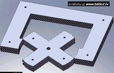
The rotor cross bar face is 30 degree of an arc, just like in the Attraction Motor Update page. Fortunately my laser guy has not started to cut the S rotor plates yet. Will send him the drawings now.
Page 7:
# 181 ; by Peter Lindemann, Senior Member, 09-14-2007, 12:03 AM ; Smallest Gap, any way you can..!
Dear Jetijs, Yes, the new design will work well for you. Your idea of cutting the rotor pieces a little over-sized, and then machining them back on a lathe is the right way to think about it. If the rotor pieces are made of standard motor lamination material, they are very difficult to machine. You will need the hardest ceramic cutting tools in the lathe that you can find. Also, its an “interrupted cut” so the stresses on your rotor can be pretty high. Just take very small cuts, like .001″ or less at a time. If you can do this, you should be able to practice a .1mm gap on both sides for a total gap of .2mm. (Also, don’t forget, when you take a .001″ cut on a lathe, you are taking .001″ off the RADIUS, which is actually .002″ off the DIAMETER of your material.)
When you get to designing the circuit part, post that here to so I can help you with that as well. I’m committed to your success. Every mistake we can catch BEFORE you spend any money is cheaper to fix!
# 183 ; by Peter Lindemann, Senior Member, 09-16-2007, 12:51 AM ; A slightly different take…..
Quote: Originally Posted by nali2001 ; Just to drop a design note in: It also in advantageous to put the coils just at the ‘contact’ surface.
Like this: http://home.planet.nl/~sintt000/Core.jpg
By doing that you eliminate a lot of ‘travel’ for the flux to reach the ‘point of action’. Which means far less steel losses, better response and stronger interaction. Also will this slightly lessen the need for sub micron airgap sizes.Anyway it’s only a slight design change but it has ‘huge’ (relative term) benefits.
End of quote.
Steven, I appreciate your experience in this field, as I know you have built and tested multiple machines in this genera, but my understanding of the benefits of placing the coils right in front of the gaps is slightly different than yours. I do not believe the benefit is due to lowering the steel losses since the total flux going through the steel is the same regardless of coil placement. I believe the benefit is due to lowering the amount of stray flux that might find its way around the coil in the air when the coil is on the back leg. This loss is quite low as soon as the iron piece starts filling the gap for the motoring process to begin. Jetijs has a viable design with the coil on the back leg and this will work well as a first model for him. I used this method with the Flux-Motor in 1983 and it works well.
Also, in my experience, there really is nothing that can compensate for not having the very close air-gaps. The closer the tolerances, the higher the mechanical energy production at no extra running cost. Since “free mechanical energy production” is what this motor project is about, why not go for the max? Peter
# 185 ; by Peter Lindemann, Senior Member, 09-18-2007, 11:54 AM ; Iron Lip in the Solenoid…
Quote: Originally Posted by sykavy ; Does it make a difference to taper the iron like you showed in your video on the lip of the solenoid? I thought that less iron made less attraction. Was I wrong?
End of quote.
Sykavy, In my DVD, the intruding lip of iron inside the solenoid is not necessarily the best design. I used this to illustrate my point that Teal’s Magnipulsion Engine used SOME design feature to accomplish a close air-gap alignment at the beginning of his power stroke when the crank was still in mid-stroke. Since making the DVD I have thought of other designs that are even simpler, that accomplish the same thing.
There is nothing magical about tapering the iron. In some designs, it helps shape the magnetic field to produce an advantage. In other designs, it doesn’t help at all. These things are best worked out in your test models. Peter
# 186 ; Jetijs, Member, 09-20-2007, 02:15 AM
Peter, just received my parts from the laser cutting guy. Here are some photos:
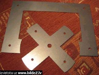
Here’s a close up. You can see that the quality of the cut is very good: …
The sheets are 1mm thick. They were cut using O2 gas for cooling. The quality would be greater in they were using N2, but that would be more expensive and the cut with O2 is already almost ideal. The material is not a standard transformer iron, because they did not have such material. This is regular steel with some carbon content. It is magnetic. I made an experiment, I put a strong neodymium magnet on one of the plates, then I removed it and put a small needle on that plate I pulled the needle slowly in the air and noticed, that the plate tends to lift a little bit. That means that the plate became magnetized. I know, that this is not good. What do you think? Will it still work? Is it wise to continue with the construction if this material is used? Or should I start to look for other materials? Thank you, Gatis
# 187 ; by Peter Lindemann, Senior Member, 09-20-2007, 10:53 AM ; Iron has residual magnetism
Jetijs, Your motor core parts look excellent. While it is true that the residual magnetism in this steel will reduce the efficiency of the motor, it will still operate. Since this is your first unit, you could still learn a lot by going ahead with what you have. It’s a shame to waste the money on the wrong core material, but since the money is already spent…… Its your choice. Peter
# 188 ; Jetijs, Member, 09-20-2007, 05:45 PM
Ok, I will carry on, since the core material is the most expensive part of this setup and I already have everything else. I will cover the plates with a thin layer of varnish to isolate them form each other. Then I will screw the parts together and do a little lathe work to get the rotor a correct spacing. As you said, I will at least learn a lot. I will inform you about my success.
EDIT: I am glad to tell you, that it was a false alarm with that rotor material magnetizing. Turns out, that not the rotor plate remained magnetized, but the iron needle. I tried this test again with more needles and this time I did not allow the needle to interact with the magnet directly, only with the rotor plate.
That’s a big relief for me, I have even considered to heat treat the plates to change the material properties, but now I wont need to do that
# 191 ; by Peter Lindemann, Senior Member, 09-21-2007, 12:19 PM ; Potential Problems…..
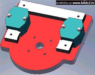
Quote: Originally Posted by Jetijs ; Peter, I am not ready for the circuit now. I will first put all the mechanical stuff. I have come up with such a design:
The shaft will be made of stainless steel and will be supported by two bearings. The long distance between bearings is to minimize the wobling of the rotor that is caused by inaccuracies in bearings. Each bearing will be put between two aluminum holders. I think I will make the base plate out of hard laminated plywood. The dark cylinders are spacers, that hold the startor in exact same height as the rotor. By adding or removing washers on the distancers it will be possible to adjust the height. I think that I wont have any problems in making these parts with my homemade cnc machine. I already have some experience in building a similar device with magnets as my Bedini SSG, here’s a picture:
http://www.bildez.lv/bildes/jetijs/visadi_strunti/1187211446.jpg
http://www.bildez.lv/bildes/jetijs/visadi_strunti/1187211881.jpg
Please tell me what you think. Maybe you have some suggestions? I am sorry about my english in specific terms, I’m from Latvia. Thank’s, Gatis
End of quote.
Jetijs, The idea of mounting the rotor on a block with bearings that won’t wobble is excellent and necessary to hold the systems close air-gap. However, supporting the iron core up on thin mounting posts, especially right next to the rotor interface, will not be able to resist the hundreds of pounds of magnetic attraction across the gap! This stator mount method will fail, for sure.
Each side of the stator interface to the rotor should be mounted firmly on a block of thick plastic that bolts firmly to the base plate. When the coil magnetizes the core, the stator pieces that face the rotor must not be able to move AT ALL!!! Don’t assume that the shape of the iron stator will not de-form under the extreme magnetic attraction forces present.
This part of your frame design MUST be reconsidered. Peter
# 193 ; by Peter Lindemann, Senior Member, 09-21-2007, 11:17 PM ; Much Better!
Quote : Originally Posted by Jetijs ; Thank’s Peter. You are right, I have not considered that factor and will redesign that frame part. As you said, I assumed, that the thick iron startor piece wont deform.
EDIT: Ok Peter,I reduced the lenght of the spacers and increased their diameter. Also I lowered the rotor/bearing assembly closer to the base plate. I think, that such thick distancers will do better than those thin ones in previous design. And if the nuts on the leadscrew through the distancers are screwed on very tight, then I think there should be no problems at all with the startor movement. The use of distancers also gives space for the coil. Is that ok or still not too good? Because I have some other ideas as well. Thank you, Gatis
End of quote.
Jetijs, Much better. This will probably work. What I was thinking of would be even stronger. My suggestion is to produce larger, square blocks of plastic that bolt to the base plate. Then, machine a slot in the top of the plastic mount plates that the iron sections fit into. Then top that with another plastic piece that clamps down on the top of the iron and screws into the plastic block. This leaves no room for movement. All of the stress is at the rotor/stator interface, so these plastic blocks only need to be out at the ends, still leaving an open space for your coil on the central leg. What do you think of this idea? Peter
# 198 ; Jetijs, Member, 09-22-2007, 02:37 AM
Bryan, no problems, you can use my images if you want. About your motor, did you mean something like this?
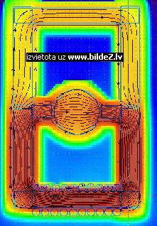
You can see, that the flux lines are more dense and compact and all the flux flows through the ball in the middle.
But see what happens if you add an adittional coil:
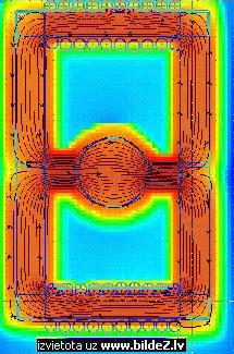
I really don’t know if that’s better. Thank you, Gatis
# 202 ; Jetijs, Member, 09-22-2007, 04:36 AM
Bryan, my english is not the best, I am not sure, that I understood your picture and explanation completely. What did you mean with the red + and the yellow -? Were those supposed to be coil windings? The flux in my pictures is represented by those lines. The arrow shows the direction, but the line density shows the strength of the magnetic field – the more lines, the stronger the field also the darker the red color. There is much interesting stuff about magnets, for example how the real field around a permanent magnet looks like. In school we are shown the experiment with magnet and iron fillings and how they form lines of force around magnet. But there is a theory that these lines are not exactly what they ares supposed to be, because in a magnetic field, the iron fillings become a magnet themselves and can freely move to a needed position. Actually a field around a magnet is a bit different. The magnetic lines come out of the N pole of the magnet, but instead of going in the S pole, they go to the middle of the magnet. The same happens to the other pole. To see if it is really so, I bought a magnetic field viewing film and put it on a strong neodymium magnet. See for yourself:
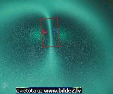
This happens because the small particles in that film cannot freely move, only turn around themselves. That shows the real field. This is the principe how the Perendev motor should work.
I do not want to speculate about this and also this theme is offtopic for this thread. Lets talk about that in my perendev motor topic
Anyone tried to build a Perendev motor? http://www.energeticforum.com/renewable-energy/963-anyone-tried-build-perendev-motor.html
# 204 ; by Peter Lindemann, Senior Member, 09-22-2007, 10:36 PM
Quote: Originally Posted by bmind ; First I would like to thank Peter Lindemann for releasing the DVD. I saw about 45 minutes last night and got me very excited. I can not wait to go back home and finish it. I am very interested in magnetics and am reading whatever I can get my hands on. I have decided to build a motor with circuit of Peter suggestion posted on “Rotary Attraction Motor”. Peter, I would really appreciate if you can tell me which materials (for rotor/motor) would be best suited for maximum torque? In the design you mention Iron. Since there are different types of Iron; is there specific requirements (for Iron) to achieve the maximum torque? I am an engineer and have access to machines that can hold tolerances up to 0.05mm (per side). I really wanted to test some of this theory to get a better understanding of magnetics.
Peter release of this DVD should be applauded. I understand the claims of some people that have worked on this and I agree with them. But I still think that the right thing to do is to give people the knowledge and not let it die with you. Get people excited, together we can achieve much more then individually could ever have hoped for.
End of quote.
Dear bmind, The best type of iron for the rotor and stator is cast iron. This is “true cast iron” and not re-cast with a mish-mash of steel and other grades mixed in. Real cast iron loses 100% of its magnetism after a magnet is withdrawn from contact, and this is the most important feature you are looking for.
Thanks for your enthusiasm and support. As you build your model, stay involved in this forum so others can see your process. Thanks, Peter
# 205 ; by Peter Lindemann, Senior Member, 09-22-2007, 10:54 PM ; Precisely…..almost
Quote: Originally Posted by Jetijs # 196, 09-22-2007, 02:19 AM ; Peter,did you mean something like this?
If yes, then I must say, that this approach would be a bit tricky to make, because the slot in that plastic piece must the be very precise. If it will be too wide, then the startor will move inside it. If the slot is too narrow, there will be problems getting the startor inside. This design is harder to make (at least with tools available to me). My previous design is easier to build (at least for me). I think I will stick to my design and see how it works. When it will be assembled I will just need to attach the coil to a battery and see if the startor is moving or not. If everything will be ok, then we know, that this design works
End of quote.
Jetijs, Yes, this is almost what I had in mind. You are still bolting the whole assembly together and to the base plate with the same bolts. What I was trying to describe was a system that bolts the bottom piece directly to the base plate. Then, if the slot is just slightly over-sized, the stator sections drop right in. Then, if the top piece has a slight clearance to the bottom piece when the stator is in place, then the clamping action of tightening the top down holds the whole thing in place. The top piece is designed to bolt to the bottom piece independently of the bottom piece’s mounting to the base plate. The assemblies can be held together with brass hardware so the whole frame is non-magnetic. I have used systems like this in other models I have built and they work very well.
But like you said, the system you proposed in your previous post will probably work, and should be tried first. Keep up the great work!
# 206 ; by Peter Lindemann, Senior Member, 09-22-2007, 11:10 PM ; Induction Motor
Bryan, From what I can tell of your description, it sounds like you have an AC Induction Motor. The age is not relevant, as this is a Tesla design from the 1880’s. They build motors exactly like this today.
This motor produces a “rotating magnetic field” and drags the rotor around behind it by a combination of induced currents and hysteresis. In spite of the physical design similarities, the operating principle is totally different. Attempts to modify this motor to run on the new principles discussed in this forum will require a lot of work.
They would include modifying the shape of the stator sections where they interact with the rotor and replacing the rotor with an iron rotor with a close gap. Plus, a commutator still needs to be added to switch the stator fields on and off at the appropriate times, along with the switching circuit and energy recover system. So, it can be done. Glad to see you are going to build a model!
# 207 ; adam ant, Senior Member, 09-23-2007, 12:21 AM
thanks Mr. Lindemann for your input., the commutator shouldnt be a problem, and i just received enough parts for the circuit.
cutting the stator will be alright, the cost of a new laser cut one will be my motivation !! this will make rewinding the coil much easier as well. the rotor is going to be an issue though, but i do believe it is already iron.
the air gap is so tight that i cannot push a piece of paper through it. there are VERY tiny brass shims that maintain its integrity, and the bearings still seem to be in excellent shape. they are positively lubricated by cloth discs that are on the shaft. -bryan
End of page 7 of the thread.