(page created for November 2007 update)
Peter Lindemann posts on Energetic Forum about the Attraction Motor Concept
From http://www.energeticforum.com/renewable-energy/271-electric-motor-secrets.html
Page 8 of the thread
# 211 ; by Peter Lindemann, Senior Member, 09-28-2007, 11:59 PM ; Thanks for your question
Quote: Originally Posted by Bah ; Dear Dr. Lindemann, You state the above as if it were an arbitrarily-discovered characteristic of a certain type of motor. The relationship between Watts and Horsepower is by definition of the units themselves and has nothing to do with any particular machine. Is it your intention to confuse the reader or are you really that confused yourself?
No matter the machine, the efficiency, whatever…a Horsepower is 746W…they are two different units used for expressing power and have a fixed constant relationship like feet and inches, grams and ounces, etc. Your statement is very odd and could be rather confusing to the uneducated.
End of quote.
Dear Bah, Actually, you are confused. A Horse Power is 550 foot-pounds of mechanical work per second. The unit was invented to rate steam engines when they first appeared, so people could understand how many horses the engine would replace for hauling loads. It is generally believed that 746 watts of electricity is EQUIVALENT to a horse power, but electricity itself does not perform physical work and therefore must be CONVERTED into mechanical energy using some APPLIANCE, such as an electric motor. It is taught (incorrectly) that an electric motor CONVERTS electricity into mechanical energy at the RATE of 746 watts = 550 ft-lbs/sec minus any losses in heat. I concede to you that commercially available motors seem to behave this way, but a close observation of these phenomena does not support this conclusion.
Everyone in this forum is well aware of the Laws of Thermodynamics and their apparent limitations. Michael Faraday’s direct induction experiment and all of the motors and generators that are derived from this geometry work equally well as either a motor or a generator. In fact, they ALWAYS work as BOTH a motor and a generator, and these functions operate in opposition to each other. This is the limiting factor in these designs. I demonstrate this in detail in my DVD Electric Motor Secrets. By using a different geometry that specifically avoids the arrangement of moving current carrying conductors through magnetic fields, it is possible to build an electric motor that DOES NOT generate any counter effects. The operational efficiencies of these motors can exceed the generally believed limitations of the conversion rates you state.
You are welcome to believe whatever you want. But this forum is for people who voluntarily wish to explore a new phenomenon. There is a great deal of information available, both on my DVD and in this forum, for you to begin to explore a new energy paradigm. You are welcome to join us, or leave, but there is no one here who needs to be “saved” from a state of “confusion” by you. Peter
# 121 ; by Peter Lindemann, Senior Member, 09-29-2007, 12:24 AM
Dear FE Student, Thanks for joining the forum. Here are some answers to your questions.
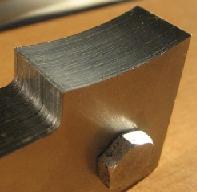
1) The Rotary Attraction Motor and the Teal Solenoid Engine both work on the principle of a single electro-magnet attracting a piece of iron to produce mechanical energy. Only exhaustive experimentation will determine which design geometry is superior for the production of torque. One way or the other, the rotary designs have fewer parts and lower friction and these advantages may still make them more desirable in the long run.
2) The solenoid and its surrounding keeper must be made of a material that conducts magnetism AND releases its magnetization when the field is removed. The simplest material to use is Cast Iron, although a wide variety of materials can be used. Teflon, Nylon and aluminum are not useful here to define the magnetic circuit, but may be useful to create supporting structures and guide ways.
3) Yes, Switched Reluctance Motors are the most efficient electric motors available today. They already operate on the magnetic attraction principle and may be able to be converted to operate with some electrical recovery as well.
4) Teal did use very sharp, strong pulses. The high efficiency window of operation will be with magnetic field strengths below saturation of the piston/keeper system.
5) The efficiency of the solenoid engine in the DVD was not measured because it is low. I have measured it and it is about 25%. The point of that demonstration was to show a motor with No Back EMF.
6) You aren’t the first to think this way. Patents have issued on this idea but other problems arise when the moving piece closes the gap completely. The impacts eventually deform the pieces and the systems make a lot of noise. Peter
# 213 ; by Peter Lindemann, Senior Member, 09-29-2007, 12:49 AM ; Learning curve….
Dear Jetijs, There is no specific wire size recommendation. Smaller wire size, such as AWG 21 will work just fine. You will find that with that wire you may have to use higher voltages to get enough current through, but you will have more turns on your coil.
The total Ampere-Turns is the field strength so there is always a trade-off. The coils with more turns will have a slower rise-time because they will have more counter EMF.
You are not going to be able to build a “final model” right away. You will have to experiment and learn.
# 215 ; by Aaron, Energetic Scientist, 09-29-2007, 12:12 PM ; Oct 1st – noon to 1pm Mountain time Interview
On Oct. 1, 2007, from noon to 1:00 pm Mountain time, as part of the Free Energy Now (Free Energy Now — Weekly Radio Show by PES Network, Inc. http://freeenergynow.net/ ) radio series, Sterling D. Allan will conduct a 1-hour interview with Peter Lindemann regarding his Rotary Attraction Motor and related technologies.”
Please pass this on…just found this on: OS:Lindemann Rotary Attraction Motor – PESWiki http://www.peswiki.com/index.php/OS:Lindemann_Rotary_Attraction_Motor
# 234 ; by Peter Lindemann, Senior Member, 10-12-2007, 11:53 PM
Quote: Originally Posted by elias ; Well, Here I read a sentence from the book titled “Theory and Calculations of Electrical Circuits” published in 1917:
“Investigations and calculations dealing with one form of energy only, as electromagnetic energy, or mechanical energy, usually are relatively simple and can be carried out with very high accuracy.Difficulties, however, arise when the calculation involves the relation between several different forms of energy, as electric energy and mechanical energy. While the elementary relations between different forms of energy are relatively simple, the calculation involving a transformation from one form of energy to another, usually becomes so complex, that it either can not be carried out at all, or even only approximate calculation becomes rather laborious and at the same time gives only a low degree of accuracy. In most calculations involving the trans- formation between different forms of energy, it is therefore preferable not to consider the relations between the different forms of energy at all, but to use the law of conservation of energy to relate the different forms of energy, which are involved.”
They have not realized that magnetic energy is not created by electricity and it is a sibling that exists with any electron flow. Thus magnetic fields are not created, but they exist. And we do not “convert” magnetic energy to mechanical, but we use it as a natural force to do mechanical work. The law of energy conservation may be true, but I don’t think that any “conversion” takes place in here, that’s why they think that it is complex and cannot therefore be calculated. Elias
End of quote.
Elias, This is a great quote. You see, once in a while, in the old books, you’d find an HONEST author who would admit that actually measuring and calculating “energy conversions” doesn’t work. I love the author’s term here, that it gives “a low degree of accuracy.” Then he says that invoking the “Law of Conservation” is simply used as a cover story!
CORRECT!!!
Its like saying that the REAL answer is so complicated to calculate, that everyone should forget about it and go with the IMAGINARY answer. Its always fun to find it in print.
OK folks. Wake up! Energy Conversions are VERY elastic and COP>1 is allowed by NATURE, if you get the GEOMETRY right. Thanks for sharing this. Peter
# 235 ; by Peter Lindemann, Senior Member, 10-13-2007, 12:12 AM
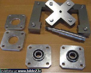
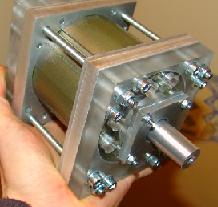
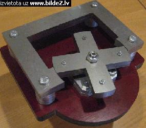
Quote: # 230 ; Jetijs, Member, 10-12-2007 ;Hi Peter, my parts are now ready. I did not post for so long, because my lathe broke down and I had to order some custom made screws to hold the plates together and that took some time. Now all the plates have some layers of varnish on them and the last layer also acts as glue and holds these plates together. Now I just need to drill a bigger hole in the X rotor middle to fit on the shaft tight. Also I need to do some lathe work to fit the rotor into the startor piece, but since my lathe is broken, I will have to get this job done by a local craftsman in his shop. This will take some time as he is always busy
End of quote.
Jetijs, This looks very good. Here are a few suggestions for your next steps.Consider sandwiching the X rotor between two plastic wheels. This will help keep your fingers out of the assembly when it is running, and give you a greater width to mount to the shaft. This will help maintain a perfectly perpendicular mounting. A stepped flange can be left on both plastic wheels so a set screw can be used to tighten the rotor to the shaft. I do not recommend a “press fit” of the X onto the rotor. In a prototype like this, everything should be left adjustable.
Next, create a plastic frame at the back of the stator to hold the wire coil in place. As the coil is wound, it needs to be supported. I’ve got some systems like this. I’ll try to get some pictures posted to show you what I mean. Keep up the great work.
# 237 ; by Peter Lindemann, Senior Member, 10-13-2007, 12:30 AM ; TRUE, but…..
Quote: Originally Posted by adam ant ; if each of the “X” arms had its own coil, and a commutator was set to engage each arm (in turn) with the stator, there would be MASSIVE amounts of torque generated in this, all from one little “spike”.
End of quote.
Bryan, It’s true that the torque can be increased with coils on the rotor, but then you have TWO MAGNETIC FIELDS interacting with each other, creating cross inductions, and the dreaded “BACK EMF”. At that point, you have a conventional motor again.
The simplest way to avoid this is to only use one magnetic field at a time. The “power-to-weight” ratio of the motor is a little lower, but the over-all efficiency is higher, and the COP is much higher.
We are purposely sacrificing the benefit of “high power in a small package” for “high power in a medium sized package” with much higher efficiency and COP. Peter
# 238 ; adam ant, Senior Member, 10-13-2007, 12:54 AM
ok, i understand that, i was thinking that the BEMF could be caught with a bifilar wind on two of the arms (opposite each other) with the back EMF being diverted the to the other two coils. then couple that with an external generator coil. (located on the opposite side of the stator coil)
but i see that the BEMF still wouldnt be stopped from travelling back through the innitial trigger wire… hmmm could diodes be used to block BEMF or deflect it backwards?
sorry, im thinking outloud. sometimes i sit and stare at my motors for hours, taking them apart, marking them with pencils, reassembling them, turning them on and off… until ideas pop into my head. i want to make 100% sure of what i intend to do before i start altering this motor… it is the only one i have. if i had money, i could test each of these ideas, but i don’t . thanks for the explanation.
Page 9 :
# 242 ; by Peter Lindemann, Senior Member, 10-18-2007, 12:44 AM ; Pictures Coming….
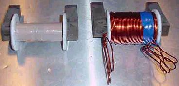
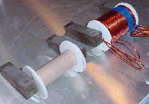
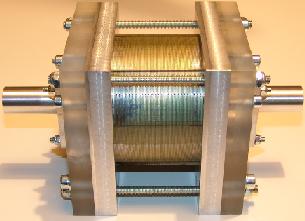
Jetijs, Last week I promised some pictures of my coil cores. As it turns out, I just happened to be rewinding my coils with a larger gauge wire, so I could take a new picture with the core both empty and full of wire. I have sent the pictures over to Aaron and he will post them here shortly. This coil is about 250 turns of #12 AWG (similar to 2mm wire).
The plastic end plates are glued right to the sides of the laminated iron cores and the bottom of the winding area is insulated from the laminations, as well. I hope these pictures help you decide how to handle the coil winding process. Peter
# 246 ; by Peter Lindemann, Senior Member, 10-18-2007, 11:16 AM
Quote: # 243 ; Jetijs, Member, 10-18-2007:
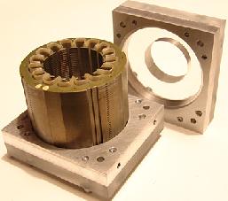
Thanks Peter, I cant wait to see the pictures although I understand what you are meaning. I have now some other problems. The guys from the machine shop said that the startor plates are glued together forming kind a cone. I you imagine the startor piece and see at it from the thickness side then it would appear something loke this:
|======/ |===rotor===| ======|
I hope you understand. The upper startor plates are closer to each other by about 0.2mm. This means that the top rotor plates will be closer to the startor piece than the bottom ones. This is not good and I have to figure out how to deal with it, because they cant do the lathe work if the startor isn’t right and they do not have the equipment to fix the startor. I already have some thoughts, but this will take time.
End of quote.
Jetijs, The machining operation to fix your stator piece involves clamping it in a vise between two large blocks of aluminum for extra support, and then using a vertical mill with a boring head in it. The diameter of the cut can be dialed out slowly .0005″ at a time. Extremely precise corrections can be made.
Support the stator pieces as much as possible because the milling operation is an “interrupted cut.” The set-up is the most difficult. Mounting the stator piece in the vice and then finding the exact center to begin the milling operation. The actual cut should take about 5 minutes. The set-up may take an hour.
Too bad more care was not taken in the gluing operation. (Aaron should be getting those pictures posted soon.) Peter
# 247 ; by Aaron, Energetic Scientist, 10-18-2007, 05:19 PM ; pics of coils
Hi everyone, Here are 2 pics of Peter’s coils:
# 248 ; Jetijs, Member, 10-19-2007, 12:34 AM
Peter,I spent all the time today figuring out how to solve the problem with my startor. There were several ideas that would require to build a mechanical device to solve this problem. Lastly I figured that I could just make a template of the startor plates with a hole in the exact center of the rotor. Then I could attach this template to the startor piece so that the tempate edges and corners lines up exactly like the startor edges and corners. This way I will have the exact point of refference to adjust my selfmade cnc milling machine. So I made the template out of a 3mm thick aluminum plate so that it matches the tartor plates exactly in dimensions. Here is a picture:
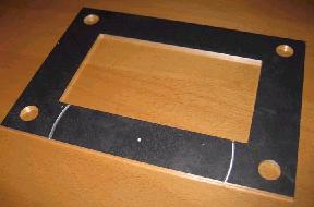
Now I have to attach this plate to the startor so that the edges are in perfect alignment. Then I will just move the endmill bit of my router to the little hole in the startor so that the endmill bit fits right in the hole. Then I will zero out all axis and this will be my X 0; Y 0 point. Now I will just have to replace the endmill bit to a suitable one and let my router go in circles, each time making the circle a tinny bit bigger
# 251 ; nali2001, Member, 10-19-2007, 02:48 AM
MOT = Microwave Oven Transformer.
Extreme Electronics – Tesla coil components http://www.extremeelectronics.co.uk/parts/index.php?page=transformers.php
# 252 ; Jetijs, Member, 10-21-2007, 09:27 PM
I finnaly solved the |==/ ==| problem.
I did it just like Peter said. The hardest part was to locate the exact center of the circle (you can see that I was a tinny little bit off the centre, but that wont affect anything). When I found the centre then I just made my cnc mill rotate the grinding tool in circles, each time with a tinny little bit greater diameter, till I got a smooth finish.
I think that somewhere around next week I will be ready to assemble the whole thing. Then there will be only the coil winding left and the circuit part.
# 253 ; nali2001, Member, 10-22-2007, 05:31 AM
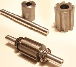
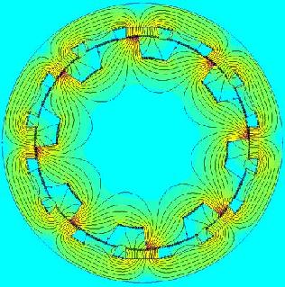
Looking good Jetijs, Man I wish I had a CNC machine. Well now, I almost finished my test thingy. It is based on the idea I explained earlier, using existing cores from normal induction motors. only the housing and rotor is custom. Well the rotor is of solid steel and the axle is aluminum. I know the solid steel sucks big time since it will bust in to flames in minutes (due to Eddy Currents) I’m not joking either since I made a experimental generator with solid steel cores at one time and I tell you within 1 minute the cores was over 80 degrees celsius. (rpm doubled under full load though, but that is a different story) But anyway I guess it should be alright for short ‘tests’. Extreme care is taken in precision machining. And so I can say that it has an 0.07mm airgap on each side. So a sheet of paper will barely fit. I also have taken metal expansion into account and measured that the rotor will expand like 0.05mm at about 100 degrees celsius. The bearing are conical ‘self centering’ rolar bearings. And due to the housing construction you can adjust the bearings in case it has some play in it. The stator is not wound at this moment. Kind regards, Steven
# 255 ; by Peter Lindemann, Senior Member, 10-22-2007, 07:40 AM
Steven, This motor looks very good. Now that I see the magnetic graph in the last image and see how you plan to run it, this could be extremely excellent. Just make sure you leave enough time for the stator field to fully collapse, and recover all of that electricity, before you turn the next set of coils on. If you do this, your motor should really perform well and prove out everything I have been saying on my DVD.
Keeping the gaps as small as you have them will produce very large torques.
# 256 ; by Aaron, Energetic Scientist, 10-23-2007, 08:10 AM ; New Youtube Videos of Attraction Motor
Hi all, Check out these 2 new vids on youtube:
Part 1 Lindemann Rotary Attraction Motor 2a http://www.youtube.com/watch?v=WvNIXyUXXqg
Part 2 Lindemann Rotary Attraction Motor 2b http://www.youtube.com/watch?v=MkRYySGrPmM
Each one is about 10 minutes long. There are 3 demo comparisons to show the difference between having the following 3 as loads:
1. short circuit
2. light bulb
3. charging a battery
You can clearly see the more you put on the back end, the less is taken from the input.
# 260 ; by Peter Lindemann, Senior Member, 10-24-2007, 01:45 AM ; Your Misunderstanding
Quote: Originally Posted by nali2001.Good videos! Nice and clear explanation. This will give the starter a good general idea what this is all about.
One thing I must address though, I don’t know how you controlled your attraction motor 20? years ago, but this one is in a sense a ‘pulsed attraction motor’ Your switching type does not care much for mechanical loads the pulse is always short, in a (“more true”) attraction motor the coils will be powered aslong as it takes to get the rotor in alignment. So that mean that there will be a higher current draw per on-time at 3rpm then compared to 3000rpm since at 3rpm the coil will be on for like seconds. If we want to also have some considerable torque of these designs we must (in my opinion) make the system so that the coil will be on as long as is needed to get the rotor in alignment and not just a short blast. Maybe some reed pulse with variable pulse width. Or some opto controller sensing a wheel with holes that are as long as a rotor alignment stroke. I know it is not really necessary at this point but I noticed from my old flux-gate gen/motor tests that you also need control to advance or retard the on-time of the coil. Since at certain rpms the slowness of the steel start to become an issue with a fixed pulse on-time. Regards, Steven
End of quote.
Steven, The magnetic reed does NOT just produce a fixed pulse. It stays on as long as the magnet on the wheel is in range. This means the “ON TIME” to “OFF TIME” ratio is the same regardless of speed! So, that does not cause the motor to draw more current at slower speeds, since the “Duty-Cycle” or percentage of “ON TIME” is always the same.
The point of these motors is NOT to make them as powerful (mechanically) as possible! The point is to make them operate in a special window, to make them as EFFICIENT as possible, which means to harvest as much FREE MECHANICAL ENERGY as you can while still recovering the maximum electrical energy.
The machine is a “balancing act” between the two outputs, as can be seen in the new videos. Tweeking the machine into this window will NOT make it produce its maximum possible mechanical energy. It will make it produce its maximum COP.
If you just maximize your motor for torque, you will recover very little electrical energy, if any, and it will run like an off-the-shelf Switched Reluctance Motor. If that is what you want, then Great, but this is NOT what this project is about. Peter
# 263 ; by Peter Lindemann, Senior Member, 10-24-2007, 12:16 PM ; Misunderstanding the Last Misunderstanding
Quote : Originally Posted by sykavy. Hi Peter, Great videos!! Congrads! to Aaron too.
I understand the demonstration is for illustration only but now I’m a little confused, please forgive me if I’m not understanding well, are you saying if we scaled up bigger this motor with stronger torque ( say for a scooter) we wouldn’t be able to recover the energy to the second battery?
End of quote.
Sykavy, No, I did not say anything of the sort. My comments were addressing Steven’s misunderstanding about the timing issues. The motors CAN be configured to produce both torque and electrical recovery, as I have said all along. Peter
# 269 ; nali2001, Member, 10-27-2007, 08:48 AM ; Answers
To Jetijs: A reedswitch would be a workable solution for some testing and such. And not everybody is going to do 3600rpm. Keep in mind that you should only used the reedswitch for triggering transistors and such and not use it as the actual switching mechanism for the coil since the current and the Back Spike will burn it out. You see them used here: YouTube – OverUnity Pulse Motor – Doug Konzen
And about the coil winding. In theory there is no difference in field strength using 1wrap at 100amp compared to 100wraps at 1amp. But it is a balance, it depends… like do you for instance actually have a 100amp source, transistor or diodes, if not don’t bother building a coil that requires it. And if one is not happy with the first coil just wind another one. (keeps you from the street)
To Lighty: The reason why most people don’t use silicon steel laminations is because there is no ‘real’ way to obtain them. That is one of main underlying reasons why I choose my design and use regular induction motor stator cores (which are of course made of precision cut silicon steel laminations) In my experience the only other ‘kinda’ available source of laminations is indeed microwave oven transformer cores (MOT) but even that is not practical since you most of the time need more than one transformer and that also means the same size/type. Ant if you salvage them from dead microwaves you can spend a few months hoping for two identical sized transformers(that is if you only need two). That is why next to nobody is building. The needed material is just not realistically available. (I’m not even talking about machining) Sure you can have a custom motor core made for you but how are we going to pay that… These are the main problems that plague this project (and field)
Regards, Steven
# 270 ; by Peter Lindemann, Senior Member, 10-27-2007, 11:47 AM ; Magnetic Reed Switch… Much Better Than You Think
Quote: Originally Posted by Jetijs. Nice Peter. I am sure that this is only the beginning. I am almost done all the mechanical stuff, there are some some minor things I have to take care of. I will post pictures tomorrow. Meanwhile I have some questions for you.
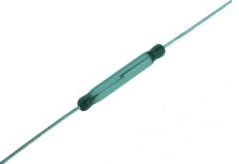
1. I was wondering about your reedswitch and its construction. I mean a reedswitch is a physical switch and I am surprised that you could get 3600 RPM using reedswitch. That means the switch fired 7200 times per minute or 120 times per second. Can a reedswitch operate that fast? Or did you use some special kind of reedswitch? I have some of these:
Will they work properly? Have you considered using hall switches?
2. When I look at your coils, I see those thick wires, but I have only gauge 21 wire, I think that this is a little too thin. Also the winding will be a pain in the … May be I could use a simple standard 1mm thick cable with plastic insulation? That way It would be easier to wind the coil and I could probably get some 300 to 400 turns on my startor. Also the resistance would be less and stronger magnetic field. Of course also the amp draw would increase. Thanks
End of quote.
Jetijs, I have used the exact type of Reed Switch you show in this picture in a motor I built 5 years ago. It had two of these reed switches firing two different circuits through the same coils in opposite directions, alternately, twice per revolution. The motor was capable of 11,000 RPM and was run at that speed often. Each of the two reeds were switching cleanly and discretely (with no over-lap) 400 times a second. These devices outperformed my wildest expectations!
They must be operated in a section of the circuit that has no inductive characteristics to prevent arching at the contactor. My current demonstrator uses the magnetic reed in just such a configuration (operating a voltage divider bridge) and has never malfunctioned.
The reason I chose these devices is that they do not require any power to operate. Both Hall-Effect circuits and Opto-Interrupter circuits require continuous “stand-by” current. While I agree that more complex circuits may benefit from optical commutation, your single coil with an X rotor will run very well on the magnetic reed as the control device. The “trick” is to set up the physical spacing between the magnets and the reed to get the proper On/Off timing. Don’t be surprised if it takes an hour or more to tweek this into perfect operation.
As for your wire size, the motor will run if you wind the coil with #21 wire, but it won’t run very fast, or have very much power. The reason is…….too much inductance. The current “rise time” will take up the whole window as the Rotor is attracted to the Stator, and even be turned OFF before rising to its maximum. Consider trying to find different wire for your your coil. I would recommend at least #16, or as large as #14. Currently, my coils are 250 turns of #12, but my unit has four of these coils and an optical commutator. (I’d have it running by now, but I have been diverted by another project for the last few weeks.)
As for winding the coils, I built a special jig that holds the core by one of the bolt holes and chucks up into my variable speed Mill. At about 30 RPM, winding becomes manageable. It will take more time to make the tool for winding than it will to wind the coil. But after that, unwinding and rewinding with different wire is simple. I hope this helps. Peter
Page 10:
# 272 ; adam ant, Junior Member, 10-27-2007, 12:20 PM
@Jetijs and @nali2001: I didn’t know it’s so hard to get the transformer silicone steel. It’s extremely cheap here and easily obtainable and I used it many times for various purposes. Some of the forms I made were quite complex but as you know it can easily be cut by water and laser (depending on the required precision and the thickness of silicone steel plate). These days I prefer to use the Mu-Metal cores but I rarely do because the material is rather expensive.
@Peter Lindemann: Reed switches are a great little component but they do suffer from slow turn-on times and slow turn-off times (a few orders of magnitude longer periods in comparison to semiconductor devices). Fast turn-on and turn-off periods are useful in more than one way and especially if you’re into energy recycling. As for the bias currents, they’re extremely low- for example an optical switch with three stages of level adjustment and logic control consumes about 30mA at 12V -> 0.36W. In comparison to the overall consumption of any motor it’s negligible.
That being said- I do recognize that reed switches are much simpler to work with and probably the best choice for fast and simple experiments.
– and in post # 274:
I’m from Croatia. The transformer silicone steel is cheap but I’m not sure how much would shipping cost since the steel is heavy as hell.
As for the Mu-Metal we get it from Germany.
# 276 ; by Peter Lindemann, Senior Member, 10-27-2007, 03:38 PM ; Try the #21 Wire First
Quote: Originally Posted by Jetijs. Thank’s Peter, I did not know, that a reedswitch can operate that fast. This is great
As for the coil wire. What about those cables with insulation? Can I use these? Because it is hard to get the magnet wire of that thickness here, but I can get a cable with insulation at every store. Here’s a picture:
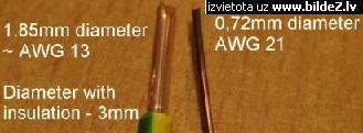
Of course the insulation would reduce the total count of the windings, but that is what is available here. I could order some magnet wire form ebay, but that would take weeks to deliver and would be more expensive. I don’t see why i could not use such a cable instead of a magnet wire. What do you think? Thank’s. Jetijs.
End of quote.
Jetijs, If you have the #21 wire, just start with that. Wire with normal insulation on it just takes up too much space, and does not cool very well, either. Start with 250 turns of #21 and see how it runs. If it seems speed limited, remove 50 turns and test again.
An alternate idea is to wind two or three coils (bifilar or trifilar) with about 100 turns each and then switch them in parallel, running each winding with its own transistor.
I do not recommend spending more money on Mu Metal or other wire at this point. Get the motor running with what you have.
As for collecting energy from the turn off of the circuit, the reed is “slow” to actuate but very abrupt at the actual point of disconnect. This is the important feature, so it works just fine. Peter
# 280 ; by Peter Lindemann, Senior Member, 10-28-2007, 05:33 AM ; Clarification, Please….
Quote: Originally Posted by lighty # 279. I beg to differ. The turn-off time of reed switch is several orders of magnitude longer than with any semiconductor. Since the inductive collapse voltage amplitude is a directly dependent on the shortness of that time it is very important to reduce that time as much as possible. Actually I compared the results when using a relay or reed switch and MOSFET. With the same current passing through the coil and the same core saturation level the inductive collapse voltage controlled with MOSFET was about 15-20% higher in comparison with electromechanical interrupters. Now, if one is into recycling the energy of the inductive collapse then one should consider using the semiconductor switches because for the same amount of current one could get back much more energy out of a coil. Of course the suddenness of the collapse is depending on a hysteresis loop of a core etc.
End of quote.
Lighty, In the tests you refer to above, are you comparing the turn off time of a MOSFET carrying current and a large relay contactor carrying current?
The little magnetic reeds cannot carry any current and I am only suggesting that they be used to TRIGGER an electronic switch, such as a transistor. And again, this suggestion is only to get Jetijs motor running initially. In order to maximize speed, power and electrical recovery, more precise methods, as you suggest, will be required. I’m just trying to help him get the motor running with what he has. Improvements can be added later. Peter
# 282 ; by Peter Lindemann, Senior Member, 10-28-2007, 04:23 PM ; Reminder….in case you hadn’t seen this
Quote: Originally Posted by lighty # 281. Ahhh, now I understand correctly. Well in that case, yup, reed switch should me more than enough for the experimental purposes. I’m just not sure about the oscillation of the triggering signal and if any debouncing is needed, although I suppose if the trigger threshold od MOSFET is high enough that shouldn’t represent any problem whatsoever. Oh, and Peter, I do appreciate your efforts and patience!
End of quote.
Lighty, Here is a link to the basic schematic of the machine Jetijs is building:
Rotary Attraction Motor Update http://www.free-energy.ws/electric-motor-secrets/attraction-motor.html
You can see that the little magnetic reed is just connecting and disconnecting the voltage divider section of the circuit. Plus, when the reed shuts off, the resistor R2 is still connected from the emitter to the base of the transistor, so the transistor shuts off quickly.
The little reed switches don’t bounce as much as the larger relays because the reed itself is magnetized. They just clamp and release. I hope this helps. Peter
# 283 ; Sykavy, Member, 10-31-2007, 01:42 AM
I was speaking with a friend about the electric recovery to the second battery. He said that the attraction motor has the advantage of using less electricity because if you tried to recover the spike from a normal electric motor you would probably blow the batery up.
The attraction motor also stays at the same level of input while the normal electric motors vary up and down making recovery very complicated. Does this sound right?
# 284 ; nali2001, Member, 10-31-2007, 09:46 AM
You can indeed pulse drive a normal big dc motor and recover like 80% and drive a second somewhat smaller motor from that, and so on(which is already o.u right there). But these motors normally do of course draw more under load. You can recover the back spike of nearly everything that is pulse driven, including transformers. Your battery won’t really blow up since it is possible to transform the spike to lesser voltage. Regards, Steven
# 286 ; Jetijs, Member, 11-02-2007, 03:39 AM
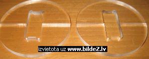
I finally got all the parts assembled to see how small the gap is. I must say, that it is a pain in the ass to adjust everyhing, it takes a lot of time. But when I was done, the air gap on each side was about 0.3mm or so. I could probably get it smaller, but I made too many mistakes in the building process, to the gap is as wide as it is. But its good for a prototype. Tonight I will work on the plastic coil holders. I will make them out of plexiglass and glue them on the startor with epoxy. Then all whats left is to wind the coil, but that should be easy enough. Here’s a picture:
The gap on the farthest side looks kinda big, but that is only the shaddow, because the rotor is in a little bit lower position than the startor
Edit: Here’s the coil holders:
# 287 ; by Peter Lindemann, Senior Member, 11-02-2007, 04:46 AM ; Awesome Work!!!
Jetijs, Excellent work. Thanks for the picture. This machine will allow you to test a wide variety of the principles in my DVD. With the air-gap at 0.3mm per side (0.0118″) your total air-gap will be 0.6mm (0.0236″) or very similar to the little demo motor I have here, so you will not be able to see high torque production. No problem, just keep going and finish it. Its a great start for your research efforts and learning.
# 288 ; Jetijs, Member, 11-03-2007, 09:09 PM
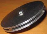
I made the comutator plate with magnets yesterday. The plate is made out od 3mm thick aluminum and the magnets are 1/4″x1/4″x1″ neodymium type. They are spaced 90 degree apart of each other, the plate is bolted to a thread in the other end of the shaft, here’s a picture:
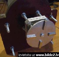
My coil holder plates are also done and glued to the startor. I am almost done
# 290 ; Jetijs, Member, 11-03-2007, 11:31 PM
Thank’s Bryan. I have not studied anything of this is some engineer school, I had to learn everything by myself. In fact I am just a computer technician and a system administrator. We just have many tools and machines where I am working, so I have a chance to learn how to use them. Also I have built my own cnc machine, this gives me the freedom to machine almost any part I need. Here’s a link: Ðtrums vol.2 – BOOT.lv http://www.boot.lv/forums/index.php?showtopic=53294
# 291 ; by Peter Lindemann, Senior Member, 11-04-2007, 12:13 AM ; Commutator magnets will fly…..
Jetijs, As usual, your workmanship is excellent. I will caution you, however, on the design of your commutator wheel. Your motor will be capable of very high speeds. I assume your little magnets are glued onto the aluminum wheel. At some speed, the glue WILL fail, and you will embed one or more magnets in a wall, ceiling, or your head! Please consider mechanical restraint.
Also, you will see very shortly that the little reed switched are very sensitive and the magnetic field around your magnets is very strong. You may not be able to get the timing you want with magnets that big. The best way to test the placement of the reeds is to connect them to a continuity meter that makes a sound and start moving the reed around the magnets. When you find a location that seems to be commutating properly, build a structure to hold the reed in that location. Good luck, Peter
# 292 ; Jetijs, Member, 11-04-2007, 12:24 AM
Peter, what if I make a second disc with grooves for magnets and glue it on the other side of the magnets? This way the magnets will be gluded between those two plates, and also pressed together with the screw. I used a strong epoxy designet to glue together metal. I think this should work. But I have also been thinking about the size of the magnets. These are the smallest ones I have. I will try to use them and see how it goes, If they are too strong, I will gave to get some smaller ones. Also for timing adjustment I was going to use a simple relay. I will attach the relay to the reedswitch so that it makes a clicking sound when a magnet passes by. Thanks.
# 295 ; Jetijs, Member, 11-04-2007, 12:58 AM
Thank you all for the kind words and the encouragement. Jan H, I have not any experience with attaching magnets to anything that rotates at high speed, but I have used this kind of epoxy in various other applications, it has never let me down. This is what I am gonna use:
I am sure, the magnets wont fly away in such configuration. Thanks
# 296 ; lighty, Member, 11-04-2007, 03:16 AM
Simply add a thin layer of mylar or some similar non-magnetic, non-elastic, strong material. Glue it with epoxy adhesive along the circumference to cover the magnets and it will hold your magnets 100% no matter how fast you spin them (I tried that configuration long time ago and it works on high speed constructions).
Since the magnets are quite powerful you could also remake discs and leave a 1-2mm of material at the outer end of the groove to hold the magnets. That also works flawlessly.
The third option would be to use the optical switch as I suggested earlier since with it it would be much easier to have a lighter disc made out of some polymer and would be much more versatile in shortening or lengthening the switch-on and switch-off times.
BTW- that’s a beautiful craftsmanship. Last year I made some working models of Tesla’s devices (Tesla turbine, Tesla induction motor, big Tesla transformer and a huge model of Tesla’s Egg of Columbus) for the Tesla’s Memorial Center in Smiljan and I thought the technical problems would never end. Especially when all the parts should work as well as look good and antique. That thought me to appreciate this kind of stuff. Great work Jetijs!!! Great work indeed! Oh, and am I mistaking or did you use the SW for the CAD modeling?
P.S.: Could you give me the rough estimate of the dimensions of your construction so that I can ask my supplier how much would silicone steel sheets cost (a rather minimal price I should say) and maybe arrange some kind of cheap transport to Latvia? Usually I wouldn’t go to such length to help people I don’t know well but you’re one of the rare people that I see to do practical work and actually know what you’re doing from the engineering point of view.
# 297 ; Jetijs, Member, 11-04-2007, 04:18 AM
Thank’s lighty, Yes, I use Solidworks for 3D modeling my parts. I must say that solidworks is far more easier to learn than AutoCAD. For the dimensions, the rotor is about 120mm in diameter that is about as big as a CD. I would appreciate your help with material very much, since I searched for the silicon steel here in Latvia for a long time and did not find anything. Thanks
# 299 ; Jetijs, Member, 11-04-2007, 04:30 AM
lighty, I will finish this setup and do some tests to see how good does this work. Then, if everything works out good, I will design another – better model. Only then I will be able to calculate the necessary sheet size. For this model I used 1mm thick steel sheets. I know, that this is not the best choice, but that is all I had and it is still better than to use one big metal piece of both startor and rotor.When I will be ready to make the other model, I will PM you. Thank’s and get well soon
# 300 ; adam ant, Senior Member, 11-04-2007, 05:55 AM
Jetijs, you can easily use liquid resin and dunk the whole thing into it. when it dries it is a very hard, very strong plastic that should hold up to any speeds you can throw at it. i have resin experience with making molds and such, and they also use them in off-roading ignitions. (water proof it) if it turns out too think, shaving it is very simple, and if it is too thin, multiple coats are also easy. you can get a quart for around $10 us.