See also the HV Marx Generators page zpe_marx_generator.html, and the page Spark Gaps zpe_sparkgap.html
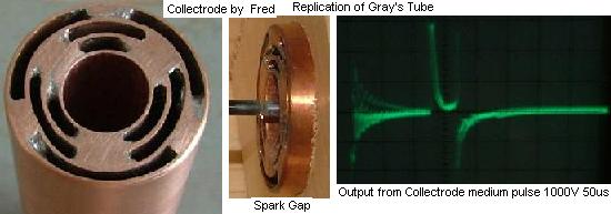
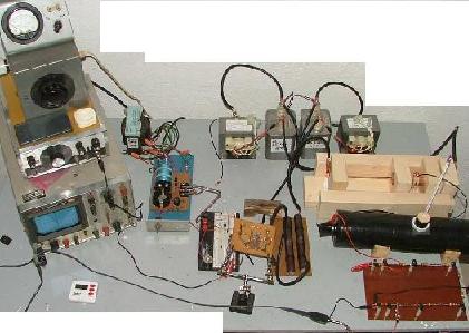
## Replication by Fred from files of the YahooGroup ‘alfenergy’
(to link the article above use: #EGST3 )
## THE ANSWER, http://www.linux-host.org/energy/the_answer.htm
This diagram above may be the answer to free energy , that we have all be looking for and an explanation as to how the Ed Gray Device may have worked. And thanks to Peter Lindemann DSc, and his patent search into additional material of Ed Gray Patents of which it seems no one was aware until now, seems to have. uncovered something we may all now use to make some headway in our experiments towards getting free energy.
This article can only be a brief outline on how it works, for a more comprehensive explanation I suggest you get the book or video entitled the Free energy secrets of cold electricity by Peter or visit the following Free-energy cc http://www.linux-host.org/energy/www.free-energy.cc website for more information.
I have also added the Gray patent from which Peter gain some insight giving as to how the Ed Gray conversion tube may have worked.
This is an additional patent http://www.linux-host.org/energy/graypatentjun.htm to the one many have seen of motor and gives some additional information on the electrical generation involved in its running .
It seem now the secret to unlimited electrical energy will rest of us understanding the diagram and the information contained in Ed Gray additional patent material as presented here..
The conversion tube device is it seems powered from a high voltage DC source of several thousand volts and is fired in a pulses of extremely short duration and in a rapid succession and not allowing the power to reverse it direction of flow.
The secret seems to be also in the way a high voltage discharge occurs across the spark gap causes a powerful disruption to the space and in the area occupied by the metal elements or shields.
It is not known what material these metal electrostatic elements were made of or how thick they were ,but a shiny metal copper is assumed to have been used .for these electrostatic elements ,although stainless steel would probably also work as well.
The metal for the spark gap rods is probably made of something common as well, and may consist only of one type of material ,but I have heard via the web that spark gaps are known to work better when they are comprised of two different metal types, for example lead and iron, this may also be case here as well
The voltage must be able to travel in one direction and not be able to oscillate and find an energy balance level and cancel the effect we are looking for…
If you have access to the twin books of The Nikola Tesla Patents ,Lectures and articles check out his work on his pulse experiments, I have unitil now assumed they were something to do with his high voltage high frequency experiments ,It seem that I like others have misunderstood it, and that these experiments do indeed hold the secret to free energy.
Some of the results that Nikola Telsa seemed to have observed, was the formation of unusual light displays after high voltage discharges ,that it seems headed out into space. ,It is interesting to note now and just recently that natural lighting observers have just become aware of unusual light manifestation called sprites jumping into space after a powerful natural lightning discharge.
The big cans of the Testatika may also be a version of this spark gap tube arrangement, the Wimshurst part of this well know machine within the free energy scene, is quite capable of generating the electrostatic charge needed and could also be the secret that up to know has been kept hidden from the rest of us. Could it be really as simple as the diagram above..
It is common knowledge that when a terminal is closed on high voltage dc power circuit there is enough energy released at time of circuit closure to kill the person throwing the switch unless special precautions have been taken (where did this excess energy come from ) after the contact switch has been successfully thrown the danger is no longer there , the system now acts as it was safely designed too.
The following information has been taken from the Book The Free Energy Secrets of Cold electricity by Peter A.Lindemann, D.Sc
Published by Clear Tech inc ; P.O.Box 37 ; Metline Falls WA 99153
# Summary of The Electro-Radiant Event
1. The Electro-Radiant Event is produced when a high-voltage, direct current is discharged across a spark-gap and interrupted abruptly before any reversals of current can occur.
2. This effect is gready increased when the source of direct current is a charged capacitor.
3. The Electro- Radiant Event leaves wires and other circuit components perpendicular to the flow of current.
4. The Electro-Radiant Event produces a spatially distributed voltage that can be thousands of times higher than the initial spark discharge voltage.
5. It propagates instantaneously as a longitudinal, electrostatic “light-like my” that behaves similarly to an incompressible gas under pressure.
6. Electro-Radiant effects are solely characterized by impulse duration and voltage drop in the spark-gap.
7. Electro-Radiant effects penetrate all materials and create “electronic responses” in metals like copper and silver. In this case, “electronic responses” means that an electrical charge will build up on copper surfaces exposed to Electro-Radiant emissions
8. Electro-Radiant impulses shorter than 100 microseconds are completely safe to handle and will not cause shock or harm.
9. Electro-Radiant impulses shorter than 100 nanoseconds are cold and easily cause lighting effects in vacuum globes.
# A email message from peter:
Thanks for linking to my site. I really appreciate the support. Just a note to clarify your excellent diagram. The top electrode in the tube actually is connected to the positive of the battery, not back to the “high voltage source” as you indicate. Gray called this his “low voltage anode.”
Also, from the photographs we have, it looks like Gray had at least 4 grids in his tube. We’re making a lot of progress. One friend of mine fried a 1000 amp meter with an impulse from a system whose input was less than 12 watts.
Another person reported to me that he had so much electro-radiant event backing up in his primary, it kept his capacitor charged, and the system kept running even after he shut off the supply. We are definitely getting close.
I’ll keep you posted. Thanks again for the support!Sincerely, Peter Lindemann, DSc
# Splitting the Positive:
It has come to my attention that Edwin Gray when describing the workings of his device used a term called SPLITTING THE POSITVE to explain how his device worked.
I have been drawn to the attention of a simple circuit as above that apparently Jerry Decker has at his website for some time that may explain the resulting action . keelynet.com
I have tried this experiment myself as per link below.
I would suspect the battery sizes are not critcal but personally I am going to use three six volts batteries as they seem to be the easier to connect as above.
Two Batteries are connected in series that positive lead is connected to negative lead and so on. The third battery connection negative to negative.
So now that you have two leads free that come from the positive side of the third battery and a postive lead from the other two batteries as per circuit diagram.
These two leads are then connected to a small lamp as shown in circuit diagram. I am going use a lamp globe rated at 6 volt’s
The circuit is simple enough so other’s reading this may like to try this for themselves and then let me know how you get on.
My experiments using the above circuit http://www.linux-host.org/energy/battery.htm
(to link the article above use: #SGE )
## Edwin Gray’s Energy System, http://www.icestuff.com/~energy21/edwingray.htm
Thomas H. Moray invented a specialized high efficiency 6,000-hertz power supply. It turns out that Edwin Gray’s device also produced this same exact frequency. Certain electrical equipment such as solid state radio, television and light bulbs will operate on this 6,000-hertz electrical current.
The overall efficiency of the Gray device is extremely high. From one of his company press releases we are told that it will power loads four times longer in comparison to a standard DC to AC inverter power supply. This particular press statement indicates that he was planning to market a device that outputted a 6Khz frequency, as compared to the standard 60Hz frequency coming from the public utility power grid.
Both the Moray and Gray energy systems harness a very old source of energy in very unique ways. They are the solution to our power needs using an inexpensive renewable energy. The advantages over other systems are many. The World is indeed moving at a suicidal pace, we need this technology more than ever. It will light lights, run motors and electrical appliances.
Getting back to the Gray device. It is a fact that when you put a high potential current across two opposite elements, ionization will occur between them. The high voltage elements 12 & 34 develop a pre-discharge plasma glow between them. This is a given unless the elements were to exist within an extreme vacuum environment. The Gray conversion tube acts no differently. When a glow pre-discharge is present the tube is switched in the on mode and current flows. Without this ionization between the cylinder and rod in the conversion tube no current will flow through the load.
Discharge occurs across the spark gap 62 once this capacitor reaches the breakdown voltage of the gap. Once the arc is broken it begins to recharge the cycle repeats and the cycle repeats so long as the batteries remain charged. The current path flows along the red wire shown in Figure – 7. Ionization drops in the conversion tube 14. The load current is halted. When this discharge takes place the anode 12 is heated. Most of you are acquainted with the fact that the space between a hot filament emits electrons and a cold electrode by which these electrons are attracted is unilaterally conductive. Current can flow only from the hot filament to the cold electrode. It is known that when an electron moves through a magnetic field, whose lines of force are at right angles to its direction of motion, the electron is constrained to move in a circular path.
In fact, if the field is made strong enough the electron may be forced to stay in the field and revolve in a circular orbit whose diameter is smaller than the field. If a magnetic field is applied transversely to the motion of the electrons the electrons may be deflected to such an extent as to prevent them from reaching the plate and to constrain them to return to the filament. A.W. Hall of the General Electric Co. was the first to use this principle in highly efficient vacuum tube converter he called a magnetron. The sudden discharge in the converter tube generates an intense magnetic field that very abruptly halts current flow to the load. Directly thereafter the magnetic field collapses.
The collapsing field in conjunction with the reappearance of the pre-glow discharge instantly generates an electrical surge of power. This surge is unidirectional and can run motors and light bulbs with extreme efficiency because DC resistance does not limit this type of current and wasteful heat loss is practically non-existent. The output if feed into a tank circuit can produce high frequency currents. Old storage batteries are preferred because they can hold up to high voltage discharges. In time the recovered spark discharge will clean off the sulfur that has formed on their plates.
Edwin Gray Energy System – Figure 7
1 – The blue wires represent the current path that powers the load.
2 – The red wires represent the current discharge path that occurs when the spark gap in the conversion tube fires.
3 – When the capacitor is discharged an intense magnetic field is created within the tube. This field instantly halts current flow to the load.
” Reproduced from Radiant Energy Power Generation” (millenium edition) by Bruce A. Perreault http://www.nuenergy.org
(to link the article above use: #SGP )
## Found this on P2P, The Fuelless Engine Plans http://www.overunity.com/index.php/topic,577.0.html
– by ewitte, on: November 06, 2005, 06:05:06 PM
This says it was based on Ed Gray’s Motor. It contains quite a bit of information. Hope it helps!
Free_Energy_The_Fuelless_Engine_revised_copy.pdf http://www.overunity.com/index.php?action=dlattach;topic=577.0;attach=571 (2223.44 KB – downloaded 327 times.)
A simple experiment will help you understand this more:
You will need two soft iron cores, the first iron core use # 18 copper coated wire with 200 turns, the second iron core use #27 copper coated wire with 2,000 turns, now you will need a 1000 vdc x 47 micro farads capacitor or capacitor bank.
Place a volt meter on the capacitor and charge the capacitor to 1000 volts, the negative wire of the capacitor should be connected to the coil of the first and second iron core electromagnets that you have made. now connect the plus wire coming from the 1000 v cap and connect it off and on to each magnet one at a time. as you will see the first magnet will take only 1 to 2 hits before the voltage of the capacitor hits -0-, the second magnet will take about 7 to 10 hits before it reaches the -0- voltage mark. so do you see it yet. the second magnet that is using the #27 wire uses less energy to run than does the first magnet (the amperage HOG!).
I believe it is very possible to take a high amp DC electric motor and convert it into an overunity free energy motor, I have not yet done this, but I studied it for many hours and there is no reason why you can not do it. You simply take apart the motor and take close up photos of how the winds connect to the commutator, then you unwind the (amperage hog) wires, once the entire wiring is gone you then spray the soft iron stator inside and out with the lacquer paint, use 2 to 3 coats. You must prepare the surface for high voltage or it will spark and burn out and short out your #27 copper coated wire. Let dry for 1 to 2 days then begin winding the iron core stator withthe #11 wire. It may be a good idea to mark the connection of where the old wire coil began and stopped although the coil looks like one big connected coil it is not. Each coil over laps, but they are not connected, depending on the motor size, there should be about 4-8 separate coils, these must be replaced with #27 wire and put back into place, you must wind it very slowly by hand. (It will be very boring but keep thinking about the end result) Once all the winding is done you can put it back together and try it out, collect the back EMF and then it should go over unity (See our plans #411 for USD 14.95 pls shipping) THe end result will be a 12 VDC motor that once ran at 12V x 5A and ran hot, and will now run on 1,000 VDC x 10-30 mA ! and is cold. If the back EMF is collected properly the result will be a overunity free energy electric motor, replace all your motors in your house and watch the electric bill go down! And again your motor will never get hot or overheat ! Back EMF is free energy from a collapsing magnetic field generated from a coil of copper coated wire wrapped around a soft iron core, pulsed by DC voltage.
This is the Ed Gray electrical layout, every four High voltage magnet must have a 1,000 vdc capacitor bank, if you like you can try to cut down on cost by using the same inverter for all 5 hv magnets, actually I am counting the stator magnets as one even though there are 2, because they both fire at the same time. the 1,000 vac inverter is rated at about 20 – 30 milliamps.
How It How It Works:
The Fuel less Engine uses 300 to 1,000 vdc rated In the milliamps. You can use a 115 vac x 500 watt inverter connected to a 12 volt dc battery, and then step up the voltage to 300 vdc or up to 1,000 vdc using a high voltage transformer or our voltage multiplier plans which uses capacitors and diodes to step up the incoming ac current.
The HV Electromagnets: Use # 27 copper coated wire…. The more turns the better. If you do not know how to build these type of HV Electromagnets, we do sell the plans or you could try your local Library.
Without the invention of the capacitor this engine would not be possible, High voltage in the milliamps can do nothing to a HV electromagnet with out the capacitors. The capacitors quickly store the electrons and so produce a great output of free amperage… There is something else that we found that happens that we can not explain,.. something extra is produced by the high voltage that causes this engine to work. ?
So then the electrolytic capacitor bank is now fully charged and the spark plug gap is set to fire at 1,000 volts, It then ignites and a complete circuit is made to the magnets which are facing one another north pole to north pole, An explosive amount of magnetic power then takes place and both magnets repel one another, You can use that power to do work, to power a generator to keep up the batteries and to supply power to your entire home..
You know the first time I tried this I was skeptical, I started out using just two electro magnets that I made myself, We placed them on the table and I held down the top magnet just in case it did work. I didn’t want my magnet to get damaged. So with all I could, I held and pressed down on the magnet with one hand and connected the + wire lead to the 12 volt battery, then POW! It ignited and almost broke my arm off, and I still couldn’t keep the magnet from flying thru the air. That’s an experiment that I will never forget.
It is impossible to get this much power from a low milliamp source using any other electrical DC store bought motor. But our motor will do it!
NOTE: The more voltage you use the more power your engine (Motor) will have, as well as rpms. But anything over 1,600 volts will have to be well insulated. Your soft iron cores of your electro magnets will have to be dipped in paint and allowed to drip dry for 3 days. Or you can simply buy a 10 LB roll of #30 or so double or triple coated copper wire…. also buy the square type you will get more power…. and be sure to wrap wire as tight as you can, side by side as close as you can…
PARTS LIST CONT……
400 volt x 470 uf electrolytic capacitors. Connect each capacitor in series using a soldering iron, or you can simply buy a 2,000 v cap.
The capacitors shown here are electrolytic type. The capacitors will charge very quickly, they will not store much amperage, because the finer the wire you use and the more turns of wire you use the less amperage will be used to run the motor. There are other options, the higher the uf of the capacitor the more amps it will store. It will take longer on start up to charge, but once fully charged your cap will discharge very slowly because your motor is designed to run at very low milliamps of power.
Ricks DC Motor / Generator Copyright 2002
This is a research device, Capacitor and diode ratings depend on the voltage input vs what size coil wire used and # of winds.
If you use a coil that is wound several thousands of times with number 38 or 36 copper coated wire, you are going to need to use voltages from 1000 to 3,500 vdc input. The back emf will be great. # 38 wire is hair thin and hard to wind but it is the best to use for a PVC air core type magnet.
Using # 36 or 32 copper coated wire is much easier to work with. Make several coils out of old transformer iron cores. You will need to do a little cutting. This will be a great learning experience for you when you go to build a larger unit. Make one coil with #18 copper coated wire which should come out to be about 90 to 100 turns, you will notice that free energy can be collected but the coil and commutators run hot, heat loss = energy loss.
# 18 wire will take voltages from 12 to 24 vdc.
#38 wire will take voltages from 200 to 3,500 vdc. And will run very cool and use very little amperage from your DC power supply, use a 12 vdc battery with a small 100 watt dc to ac inverter.
A letter from a customer: To the technician at Creative Science,
After studying your file, ‘The Fueless Engine’, I downloaded from the internet, a copy of USP #3,890,548 for further study. These devices, as stated, appear to work by the conservation of energy, and the electromatic coupling of energy, while collecting the electron moving forces of decaying magnetic fields after physical work as been accomplished.
On page 8 of your file you state that you would appreciate any new ideas and findings. It seems easier to understand how this engine works with the concept of inductance in mind. Your file arranged like this might be easier for the layman to understand.
I noticed in the descriptions of the illustrations in Ed Gray’s patent, something that wasn’t apparent at first. Number 32 in figure1; is a second complete charging system ! That leaves me to believe that power might flow through the system like this.
In Ed V Gray’s diagrams: see figure one; The sinewave(s) are split differently, see sub-figures 19a, 21a, 22a. This might be what he considers, ‘splitting the positive’. He uses diodes (#’s 21 & 22) to rectify the positive’s of two opposite, unidirectional sinewaves.
In my opinion the negative waves of these currents are transformed/harnessed as flux. The inductors (#’s 23 & 24), along with the inductance of the magnets could influence the way the flux reacts in nature/reality. Splitting the positive(s) and exciting the currents into flux seems to be where the efficiency is achieved.
Your simplified model is sound in theory. However, the illustrations don’t contain any reference to the DELAY COILS/INDUCTORS of the charging systems, nor to the important role they play in the system. As I understand it, when current is increased in an inductor, the inductor generates a counter E.M.F. which opposes current build up. As current decreases, the inductor sets up a counter E.M.F. to try to keep the current going the same way. This is accomplished by the magnetic field expanding and contracting in the core of the inductor. This concept tends to cause the power to be ‘OUT OF PHASE’. Ed Gray states in his patent, ‘which is believed to produce a static floating flux field’. The word static, may be a reference to the way power flows at a molecular level. In the delay coils the inductance also seems to be applied as a flux (magnetic field? or?) and as a phase variant in how it interacts with other inductors (stator and rotor electromagnets). The floating part of it?? Hence, ‘static floating flux field’.
In the magnets power and current being out of phase seems to be how Ed V Gray has been able to recover so much energy. This may also help illustrate, ‘that something extra that is produced by high voltage that can’t really be explained’.
from Exotic Research Report – July/August/September 1996 – p 57:
… ‘magnetic vacuum’ created in the drum, which literally takes the pressure off of end bearings and allows the rotor to float within the drum.
The motor created power surges – one behind the other – in micro-seconds. This allowed them to direct the magnetic flux field. The magnetic flux was a coolant source, so it did not need a cooling system.
The EMA’s noise emission was far less than that of all other power sources, and Gray claimed there would be no increase in noise as the engine aged. In fact, electric-motor noise is almost imperceptible when properly suppressed.
The only external magnetic effect was that another field system couldn’t operate within the same battery system. The magnetic field orientation is 360 degrees in all directions.
Perpetual Motion? According to EV Gray, some experts believe the EMA is a perpetual-motion-engine – that is, machinery that would produce continuous movement without any outside energy source – and is, therefore, invalid. The very concept of perpetual motion violates all known laws of thermodynamics.
Gray himself refutes this belief : ‘The EMA motor is definitely not perpetual motion. Only those in the scientific world who understand the theories of physics are able to comprehend how our motor works. There’s only a handful of such persons.
Block Diagram of the EMA4 shows how energy is transmitted from the four 6-Volts batteries (power supply) to the various stages of the engine and returned. Both the Air Pump (A) and the alternator (B) are optional equipment. The Air Pump prevents Condensation around the drum and provides added assurance of air in some environments. The alternator is not needed for most applications, including use in vehicles, but may be desirable in heavy generator rigs. The electric pulsators (C), which are contained in the regeneration-recycle unit, are capable of pulsing at 200,000 times per minute (33kHz), and the pulsation at 60-120 Amps is fed back to the batteries.
(to link the article above use: #ET2 )
## Ed’ Capacitor http://www.overunity.com/index.php/topic,530.0.html
– by Jerry Volland, on: October 14, 2005, 04:07:18 AM
When Ed first started using his pulse motor techniques, he had a capacitor bank which, I think I’ve read, consisted of around 16 caps, each rated at 23 uf. As he continued developing his skill, he replaced this bank of capacitors with a single cap, used in conjunction with his Conversion Tube. Although a higher frequency of operation would allow for the use of a smaller cap, I’ve often wondered if his Tube itself had an unusual capacitance, due to the high level of static charge which builds up in the air molecules in the Tube, giving him the same capacitance as his original bank? I’ve just recently found out that there may be a correlary with one of T.H. Moray’s Tubes. In Moray’s radiesthesia patent (#2,460,707), Fig. 2 illustrates his “Sparking Condenser”. This Tube has an outer cylindrical electrode with a corrugated inner surface which acts as a brush electrode, aiming a corona discharge at a central cylinder which is surrounded by a dielectric. Moray reported that this Tube had an unusual capacitance around one Farad. Although Moray mixed radioactive powders with the dielectric to produce the effect, there still may be some similarity with the Gray Tube, since a radioactive substance gives off longitudinal rays, which is the same thing that the central electrode in Gray’s Tube does. Moray’s contention is that these longitudinal rays are modulated by the corona field, thereby producing the tremendous interstitial capacitance. This same type of non-local energy storage may occur in the dielectric of the air molecules between and around the grids of Gray’s Tube. -JV
– by Wicaksono, Reply #1 on: October 24, 2005, 08:00:39 PM
Dear Jerry, I have read the patent & it seems there are 3 types of sparking condenser :
1. Figure 2 & 3 is sparking condenser that utilizes brush discharge as ionizer
2. Figure 14 & 15 is sparking condenser that utilizes filament heater as ionizer
3. Figure 16, 17, 18 & 19 is sparking condenser that utilizes x-ray tube as ionizer
According to the patent, there is no radioactive substance used in all of sparking condenser, the radioactive substance is only used in discharge tube electrode (figure 4, 5, 6, 7).
It seems that the sparking condenser is used as HF generator, and the output is fed to discharge tube so it is mixed with radiation from radioactive substance. The similarity of these & Gray tube is that Gray tube utilize spark as ionizer. Any comments ?
Wicaksono
– by Jerry Volland, Reply #2 on: October 30, 2005, 03:55:35 AM
Wicaksono, Thank you for your research. The HF generator effect of Moray’s Sparking Condencer which you have found correlates to the report that Ed Gray referred to his Tube as an “inverter”. The high frequency generation involves the capacitive cylinders being in a tank circuit with the connective loops forming the inductances. This effect is detailed in Farnsworth’s patent #2,189,358 for his high frequency Diode Oscillator. An examination of Gray’s circuit shows that a potential exists on the grids, relative to the central rod, due to the connection – through the battery and motor – of the capacitor negative with the grids, with differing distances from the center resulting in different relative potentials on each grid. Since the RF vibration of the gas in the tube produces impact ionization, the momentary 12 Volt displacement current through the cap results in the static charge build up he referred to as ‘overshoot voltage’. As he asys in the patent, the Tube is a “switching element”, allowing the 12 Volt current to flow when the circuit is closed, with the pre-existing ionizing potential making the Tube conductive. As a result of this static charge, his system cap is totally recharged in an instant, rather than with the series of impulses first used from the transformer. This indicates his Tube has a capacitance at least as high as the system capacitor. Jerry
(to link the article above use: #ET1 )