On the Permanent Electret by Mototaro EGUCHI
Professor of Physics, Higher Naval College, Tokyo, Japan.¹ From “Philosophical Magazine” Vol 49 (1925) pp178. http://energy21.freeservers.com/eguchi.htm
# Introduction
“ELECTRET” is the name given to the dielectric which is electrized² permanently by a special treatment due to the author. Some waxes and resinous materials have moderate conductivity in their liquid state, while they are very good insulators in the solid state. The electrical conductivity of these materials varies gradually with the degree of solidification, and when the materials get moderately hard the conductivity becomes practically nil. The author let solidify a mixture of these materials in a strong electric field applied through all the time in which the solidification went on. The dielectric taken out of the field, after having been cooled sufficiently, showed very strong polarities on its two surfaces which were kept in contact with the electrode plates during the preparation. The electrization of such a dielectric could not he destroyed by several treatments, such as touching by Bunsen flame, exposure to X-rays, planing with knife, washing with some solvents, &c. Nor did it die away after the lapse of many years. From several subsequent studies, it has become evident that the electrical change of the dielectric is not of a superficial nature, but that it is a permanent internal change within the material.
The name “Permanent Electret” or simply ” Electret” was given to the special dielectric at the ordinary meeting of the Physico-Mathematical Society of Japan, February 21, 1920³. Later, I found in Oliver Heaviside’s ‘ Electrical Papers’ the section with the title “Electrization and Electrification – Natural Electret” 4. In this paper he proposed for the first time to use the term “Electret” to fill the want for describing an intrinsically electrized body, and some possibilities of electrets were discussed on the theoretical point of view. The present method of preparation was, [p179] however, obtained independently and also in a way utterly different from his discussions.
The electret shows so great an intensity of electrization that the electric force exerted in front of the surface of the electret may attain the greatest sustainable value in the atmosphere. The permanency is also so good that we have detected no sensible decaying for these three or more years since the preparation.
# Ch.1 – Preparation of the Permanently Electrized Dielectric
From the study of the variation of conductivity with the solidification of waxes and some other materials5, I came to think it possible to get a permanently electrified or more correctly electrized dielectric by allowing some kind of waxes to solidify in a strong electric field. After many trials, it has been ascertained that the disk-shaped electret of a certain size is one of the most convenient forms for several reasons, except for the cases in which special studies are wanted. The method of preparation of the disk-electret is, therefore, briefly described here.
A shallow circular metal basin B (fig. 1), depth 1 cm., diameter 20 cm., is put on a pole-plate P1, a little larger in diameter than the basin. The plate itself is placed on three sulphur insulators S1, S2, S3, which are laid on a wooden tripod stand T capable of levelling by the three screws f1, f2, f3.
As the other electrode, a hollow metal disk P2 is suspended by three insulating cords, t1, t2, t3. These cords are made of Japanese fishing-lines, Tegusu (a kind of thick silk thread), whose surfaces have been treated with a mixture of some waxes and resin to get rid of the surface leakage. The basin and the disk-electrode are coated with tin-foils (not shown in the figure). The lead sheet L is used as a weight to cause the foil tightly to attach itself to the disk.
As the preparatory adjustment, the levelling of the basin B is first effected by three screws f1, f2, f3; secondly, the hook at the end of the cord C is transferred from the arrester h1 to another h2, and the plate P2 is so regulated by three screws Sc’, Sc, Sc that its lower surface comes [p180] just up to the margin of B. Another cord C stretched through a hole perforated near the end of the guider g serves to prevent the oscillation of the electrode P2.
After raising the disk-electrode P2 up to a sufficient height, the material melted at a temperature far above its melting-point (about 130º C.) is poured in to fill up the basin B, and then P2 is put on the melted dielectric so that it rests just on the surface of the dielectric. The air bubbles, if any, on the surface of the melted material may [p181] be easily taken off by touching with a small Bunsen flame.
Care was taken to adjust the voltage of the high tension source in order to prevent any undesirable effect such as brush discharges between the electrodes along the surface of the dielectric when it solidified partially. Tin-foils were applied on the electrodes, so that not only did the dielectric not adhere directly to the metal surface, but it might also contract freely as it cooled, and when the dielectric solidified completely the disk-shaped material might be easily taken off from the basin. Moreover, with the disk-electret thus obtained, both surfaces upper (Up) and lower (Lo) might be studied at will.
# Ch.2 – The Charge of Temporary Nature and the Permanent Electrization of the Electret.
As the material for the permanent electret, a mixture consisting of equal parts of carnauba-wax and resin with or without a certain amount of bees’-wax was found to be very good as regards the intensity of electrization and the permanency. If we prepare a disk-electret of this material, joining for instance the upper surface (Up) to the positive pole of the high tension source, and the lower surface (Lo) to the negative, we first detect in general a surface charge of negative sign on the upper surface, and one of positive sign on the lower, soon after we take the electret out of the preparing arrangement. But these kinds of charges are of temporary nature, and they die away gradually, in a comparatively short time (in one or two days). After the complete decay of such charges, the surface charges of opposite signs respectively to the above gradually grow up. The positive charge on the upper surface and the negative on the lower, which are respectively of the same signs as those of the applied poles of the source during the preparation, tend to grow to their ultimate values in a few days. The manner of growth of these charges on both surfaces and their values do not vary much even when the method of preparation is modified in some way: for example, when both electrodes are completely insulated from the earth, or when either one of the electrodes is completely earthed and the other insulated. The permanency of these charges is so good that we cannot detect any sensible decay after many years. We shall call these surface charges of the electret the free charges due to its proper electrization.
1- Communicated by the Author.
2-The term “Electrization” is used after Heaviside to signify the internal electrical change of a material, which is different from superficial electrification.
3- Mototaro Eguchi, Phys.-Math. Soc. Japan, ser. 3, vol. ii. no.7(1920).
4- Oliver Heaviside, ‘ Electrical Papers,’ vol, i. # xii.
5- Mototaro Eguchi, Phys.-Math. Soc. Japan, ser. 3, vol.i. nos. 10-11 (1919).
Electrets for Power Q&A – 02/07/01
http://www.keelynet.com/electret.htm
The following information is not currently endorsed by KeelyNet because we have no direct physical evidence of the claims, though of course are highly intrigued.
This document contains unverified claims and is being posted at the request of Paul Clint: smithja@sisna.com.
– QUESTION What is an Electret.
ANSWER A solid electrically insulating, or dielectric, material that has acquired a long-lasting electrostatic polarization. Electrets are produced by heating certain dielectric materials to a high temperature and then letting them cool while immersed in a strong electric field. An electret is an analog of a permanent magnet. The Columbia Encyclopedia, Sixth Edition states;
“If you take one electret and one magnet you will get a surprise. When not in motion, these two differing objects will have no effect on one another. It is only when you move them that anything happens … and … it is not the familiar attraction-repulsion. When a pole of the magnet is in relative motion to a “pole” of the electret they push each other at 90 degrees to the direction of motion. The effect is entirely odd and immediately unfamiliar (unless you are a physics student).”
– QUESTION Can the Electret effect be used to generate power directly?
ANSWER The general concensus of the experts is no, but there are some new techniques that raise doubts about their certainty. One new technique is to mix ferrite granules into the dielectric when it is formed. A magnetic field applied at a right angle to the resulting electret’s field has a dramatic effect in maximizing and recharging the electret effect.
There is very little doubt, however, that the electret is much more effective in generating power indirectly by using it’s field to move and trap existing electro-static charges. A prime example of this are reports from amateur radio operaters of the static charges collected by coaxial cables.
A great many of the numerous claimed free-energy machines are obviously employing the electret effect to collect electro-static charge..
– QUESTION In what materials can the strongest manifestation of the electret effect be produced?
ANSWER In general the higher a materials insulating properties are, the better an electret it will form. Thus, teflon is near the top of the list, with glass, plastics and ceramics.
Another important factor in plastic materials is the strength of the polymer bonds. This factor also relates to the fact that the thinner the material is, the more intense the electret’s field because the stress on the polymer’s bond is transmitted through less intermediate material. But this is limited by the dielectric constant as well because if the electret’s field generates a voltage high enough to break down the dielectric resistence, the device arcs across its own field and self destructs.
– QUESTION Where can I learn more about electrets?
ANSWER Here are some references.
See “Electrostatics – And its Applications” by A.D. Moore (1973) is a very well researched book on electrets (p122 – 130) and electrostatic machines; “Handbook of Electrostatic Processes” by Jen-Shih Chang (1995) pp509 on electrets.
The first person to make an electret was Mototaro Eguchi, see his “On the Permanent Electret” paper in “Philosophical Magazine” Vol 49 (1925) pp178.
“How to Make an Electret” by C.L. Strong in “Scientific American” Vol 203 (Nov 1960) p202 – 210 is a practical description of how to make an electret using carnauba wax.
– QUESTION How can a small cable extract so much energy from the kinetic energy of the wind?
ANSWER Your dilemma is easily resolved. The energy collected from the cable generator is not derived from the kinetic energy of the wind.
As you may or may not be aware, the earth’s atmosphere is a gigantic capacitor. At its upper level, air molecules are constantly being ionized and then as the air circulates, the charge is eventually carried to the ground which has a negative charge with respect to the upper atmosphere.
Another source of atmospheric charge is condensing water vaper. As water evaporates, it gathers electrons the molecules in the liquid state are sharing, and leaves behind a positive charge. When it condenses in the atmosphere, it gives back the electrons creating a negative charge. This is why the cable generator’s output increases in stormy weather.
Ham radio operators will certainly confirm that a coaxial cable strung out as an antenna will pick up static charge, especially in wet, stormy weather.
So the power is derived from the atmospheric charge rather than kinetic energy. This is clearly demonstrated from the fact that the power generated is directly porportional to the square of the speed of the wind rather than the cube of the speed.
– QUESTION Still the wire hardly intersects any of the wind. Even if the power isn’t from the winds kinetic energy, how can a little wire collect so much?
Answer The cross section of the wind from which power is collector is much larger than you might think. Remember that the electret effect creates an electric field which attracts charged air molecules like a magnet attracts iron. The cross section of this field can be as great as 2 feet, so a 100 foot cable could intersect as much wind as a 16 foot diameter air foil.
There are occasions static charge is generated though two objects are not in contacted. If a charged object moves against other object, static charge of the other object will be increased or decreased. This is called as a field induced charging. The moving charged thundercloud charges neighboring clouds because of field induced charging.
– Question Have you measured the cable generators power output?
Answer Measurement of the output of the cable generator is not a simple process. The form out the output varies over several orders of magnitude for voltage, current and frequency and is thus well beyond the capability of all simple measuring devices.
As a consequence of this fact, I have devised a couple of indirect methods. In the first of these, I connected the a spark plug between the generator and ground so that whenever the generator voltage builds up to the arc-over value, a pulse of current is generated that can be counted.
Upon further investigation, this method can be termed no more than a rough estimate because the shape and duration of the pulse still varies over a substantial range. Analysis of the pulses will eventually allow us to use an average and thus devise a formula that will give a close approximation of the power output.
The second method is simple and if done properly, very accurate. We simply place a resistive heating element between the generator and ground and then into a bucket of water. The output is measured by the change in temperature of the water.
Neither of these methods takes into account the losses of the charging circuit, battery, or inverter.
– Question Does the electret effect wear out or dissipate over time?
Answer The question as to whether the electret effect wears out is not a simple one to answer. I am clearly using it in a way that is different. The fact of the matter is that, in general, the electret effect is unwanted, and engineers are normally working to prevent or eliminate it. The fact that they have to work very hard to do so is an indication that it is pretty stable. Thus, the best answer I can give is that it doesn’t wear out in the short term (years).
I have learned that when the electret effect was first observed, it was produced in a relatively soft wax and if left undischarged for a long period of time, dissipated. In order to preserve an electret device in these soft mediums, they wrapped them in foil which would have continually discharged them.
This would at first seem to to contrary to what one would expect, as the continual discharge would be, in effect, dissipating the energy the electret produced. But if you look at it from the perspective of the effect that the electric field has on the material of the device itself, it is easily understood. The electric field would produce a counter force against the molecular distortion that was producing it which would tend to undo the distortion.
This means that an electret placed in a circuit which used its field at a low level would be very, very stable.
– Question How can I determine if the cable wind generator will produce more power for its cost than I would have to pay the utility company?
Answer Again, this can only be done over a long time period because it is dependant on wind, location, humidity and possibly other lesser undetermined factors.
– Question How can I be sure that the power to a load is energy from the cable generator rather than the battery or some hidden source?
Answer This is impossible because there is no difference between them. I can take a simple circuit that charges 2 capacitors in parallel from a dead battery and then connect the capacitors in series and discharges them back into the battery. Although no new energy is put into the battery some of the batteries potential chemical energy in the battery is converted and the battery will appear to be fully charged. The charging pulses from our controller (or the spark gap-coil) is closer to the double capacitor circuit than it is to a normal battery charger (DC).
– Question How can the high voltage static current produced by the cable generator be altered to a useable form.
Answer The only practical method I have found to date is to charge a battery. There are, however, a number of people who have received patents on high voltage electrostatic motors.
Some generators with similarities to the Testatika machine are the “Electrostatic Energy Field Power Generating System” invented by William W. Hyde (US Patent 4897592 of Jan 30 1990) is a rotor/stator variable capacitance machine capable of producing 300 KV.
Other such generators are; “Parametric Electric Machine” invented by Ferdinand Cap (US Patent 4622510 of Nov 11 1986) which has a series resonant (LCR) circuit structured into it so that it oscillates – and indeed operates AT RESONANCE to ensure a high output;
“Electrostatic Generator” invented by Dan B. Le May (et al) (US Patent 3094653 of Jun 18 1963) is a very ingenious system of variable capacitance;the “Electrostatic Machine” by Noel Felici (US Patent 2522106 of Sep 12 1950) is a good standard which utilizes a valve rectifier; and the “Electrostatic Generator” by William S. Spencer (US Patent 1415779 of May 9 1922) is an early rotor/stator generator which transferred its electric impulses through a transformer to produce a higher current output.
Here is another method developed by Van DeGraff himself. For Van de Graaff’s transformer see US patents 3,323,069 (May 30 1967) and 3,187,208 (June 1 1965). These patents were not just for a Van de Graaff high voltage generator, they were for a special system devised by Van de Graaff long after his generator had been in use to convert static electricity into current electricity.
– Question How can you charge a battery with high voltage static current?
Answer Thus far, I have devised two methods. The first is simple and inexpensive but only 15-20% efficient. It simply involves breaking the current into pulses with a spark gap, and then tranforming the voltage down and current up with a coil and increasing the pulse duration with a capacitor in parallel with the coil.
The second method uses a micro processor to monitor current and voltage. The impedance is then adjusted to make the charging current as smooth as possible. This circuit can also easily protect a battery from overcharging.
– Question How does humidity affect the cable generators operation?
Answer Ham radio operaters have reported that static discharges are more common and more intense in times of high humidity or atmospheric changes resulting in rain or snow. The technical literature reports that most atmospheric charge is carried by aerosol particles of dust or water that collect 100’s, 1000’s and sometimes even 10’s of thousands of units of charge. As they collect more and more charge, these particles migrate toward the earth’s surface and constitute a major component of the fair weather current.
– Question Does the cable generator attract lightning?
Answer
– 1. Lightning is a discharge of built up electrical charges that is initiated by an electrostatic potential sufficient to rupture the dielectric (air) between the charge differential. This is facilitated by sharp pointed objects that concentrate the electric field (lightning rods and the like).
– 2. If the potential difference can be minimized by discharging the area below one of the plates (cold layer) and keeping the potential below the rupture point a lightning strike is significantly less likely to occur.
– 3. The generator system, if spread over a large area, would appear as a more positively charged area as it is “bleeding” electrons off to the ground through its load system.
– 4. thus the generator could well serve as a shield from a direct strike… BUT!
– 5. the EMP effect of a local strike could be devastating!
– Question Have you tested the cable generator in other configurations such as a spiral, grid, or vertical mode?
Answer The output of the cable generator is reduced by any alteration of the cable generator from a suspension 5 to 15 feet from the ground in a straight line.
– Question What type of cable works best?- Question Has anyone measured the ion density of the atmosphere?
Answer Not just yes, but a qualified yes. The average is 3000 ions/cubic meter. The figure is subject to stupendous variations of many orders of magnitude as shown by this quote from “Atmospheric Electricity in the Planetary Boundary Layer” by William A. Hoppel, R.V. Anderson and ohn C. Willet.
“Most atmospheric processes are interrelated and cannot be studied in isolation, but it is possible to identify one or two dominant influences.
In the case of atmospheric electricity in the Planetary Boundary Layer, however, separating the various causes and their effects can be extremely difficult. In fact, this field may be unique with respect to its sensitivity to many disparate phenomena spanning a tremendous range of scales in both space and time.
For example, locally produced turbulent fluctuations in space-charge density have an effect roughly comparable in magnitude to that of changes in the global thunderstorn activity on electric-field variations within the Planetary Boundary Layer.”
– Question The ion density does not appear to provide enough charge to account for the current generated by the cable. Are there other sources of energy contributing to the currant?
Answer Both the electric field of the earth (typically 100-200 volts) and that of the cable generator produce an effect called the induction charging mechanism.
A physical process for particle charging involving the collision of pairs of particles in an ambient electric field. Electric charge induced on the particle surfaces by the ambient electric field is made available for transfer when the two particles come into contact. Subsequent differential particle motions under gravity is postulated to result in large scale charge separation. The specific role of induction charging in the electrification of thunderclouds has not been resolved.
Another effect which is unquestionably effecting the cable generator is the double layer effect described below.
On the surface of a substance, a layer of electric dipoles whose axes have an average orientation normal to the surface. Double layers may appear on interfaces of solid and gas, liquid and gas, liquid and liquid, etc. They arise whenever media with different electron affinities (forces of attraction, or work function) are contiguous, and if dipoles are available. A net potential difference, the electrokinetic potential exists across a double layer.
Still another source of atmospheric charge collected by the cable generator are Aerosol Charges. These are particles of dust or water which form dipoles and disproportionately collect one charge or the other. Where ions carry only single or double units of charge, Aerosols carry 100’s to 10’s of thousands of units of charge. The fact humidity is such an important factor in the output of the cable generator indicates that aerosols are an important source of the energy it collects.
– Question What else would be needed besides a cable generator to provide a good alternate electrical source for a home.
Answer You would need a battery or bank of batteries, a charge controller and a Grid Tied Inverter.
## Radiant Energy Diatribe http://www.nuenergy.org/alt/radiant_energy_diatribe.htm
****THIS DISCUSSION WAS GENERATED BETWEEN PAUL CLINT and BRUCE PERREAULT in a series of e-mails between 01/29/2001 and 02/03/2001***
Bruce A. Perreault February 2nd, 2003 (revised 10/22/04) ; e-mails were edited for clarity
# Cable Generator Discussion
Static Electricity that is generated on a properly treated insulated wire will produce more than a kilowatt in a light wind, according to Paul Clint. This becomes possible because of a phenomenon in physics known as the electret effect. This effect occurs when the surface between a conductor and a dielectric obtains a permanent electric field. This field has the same effect on static electricity that a magnetic field has on iron filings.
A treated piece of insulated wire strung out in the wind will act as a Van de Graaf high voltage generator. In some conditions, a 400-foot length of wire can generate 50 kilowatts and even on a bright sunny day with a breeze of 3-4 mph, it will average 10 kilowatts, according to Paul Clint’s calculations.
# How can the static energy produced by the cable be converted into a usable form?
The only practical method I have found in the past was to charge a battery. My ionic diode component might be another way to do the conversion. I will run some tests when I get the time..
The static electricity generated can be used to charge a battery using nothing but a spark plug, a coil and a capacitor, but the process is only 15-20% efficient using conventional diodes. An efficient voltage controller must be used to keep your battery from overcharging. The circuit is needed to convert static charge into low voltage to charge batteries. The least expensive design uses a spark plug, an old automotive coil, a .001, 3 to 20kv capacitor and a ground rod.
Thus far, I have devised two methods. The first is simple and inexpensive but only 15-20% efficient. It simply involves breaking the current into pulses with a spark gap, and then transforming the voltage down and current up with a transformer and increasing the pulse duration with a capacitor in parallel.
The second method will use a micro-processor to monitor voltage and current. The impedance is then adjusted to make the charging current as smooth as possible. This circuit can also easily protect a battery from overcharging. Bill Aleks controller might be the perfect solution for the task.
Perreault Conversion Circuit
click here for an updated version:
http://www.nuenergy.org/experiments/modern_radiant_energy_circuit.htm
The electret effect is more important than you realize. Any ordinary antenna will collect charge, but without the electret effect, most of it is dissipated before it can be tapped. The electric field created by the electret effect not only attracts the charge from the air, but then it traps it in the conductor. This effect will also be produced even in a vacuum.
Virtually all insulated cable exhibits some degree of the electret effect, which the wire manufacturers consider undesirable. Treating the coax will increase the electret effect at least 10 times. Treatment cost is negligible. Obviously, the treatment process is the essential piece to receiving enough energy to be useful. Teflon tape can be dangled from a cable and wonderful results can be obtained. In a thunderstorm, using an ordinary 400-foot cable with Teflon tape has produced a continuous arc eight feet long. Essentially, what you have is a type of Van De Graff Generator. I have not witnessed this myself but this appears to be possible because a lightning discharge releases energy that has been estimated to be in the billion watt range.
# Conditioning the Cable
Buy cheap coax RF cable, that has a center wire and a shield cylindrical wire. Then cut off the outer plastic skin and put the whole cable into your oven and heat it up to about 100 degrees Celsius or more, so that the internal plastic insulation almost begins to melt.
Then apply from a D.C. high voltage source around 30 kilovolts or maybe a little less, so that there will be no arc-over yet inside the cable. Then let the cable cool down slowly again, but still apply the high voltage D.C.
When the cable has come down to room temperature again, it will be a pretty good electret!
Now hang this cable in the air and the outer layer of the shield metal (which does not have any plastic isolation skin anymore), will now attract lots of free ionized electrons from the air and charge up the outer shield metal of the cable. This way you can collect lots of more charges as before and have a much higher electrical output from this cable.
Hope this helps Regards, Stefan
The electret effect is a problem in the manufacturing of coaxial cable. This problem arises from the process used to make insulated wire; an unwanted electret effect is created. Engineers work very hard to reduce the effect but are unable to completely eliminate it. What I am saying is that all insulated wire exhibits some electret effect. The engineers go to great lengths to minimize it. The treatment as suggested by Stefan Hartmann should increase the electret effect of the cable at least 100 times, and with some cable, as much as 1000 times (depending on how hard the engineers worked). The electret effect is present wherever plastic is in contact with a conductor. It is much better to use unshielded cable and it is cheaper as well. If you do use shielded cable, it might not draw as much radiant energy. To begin your radiant energy experiments string out a 300-foot length of ordinary coax cable and do not connect the other end to anything. Use the conversion circuit in this article to convert your collected charge into electrical power. When you ground this circuit do not use the one that is connected to the electric companies meter. If you do not get at least a couple of pops per minute from your spark plug you will need to condition your cable as explained by Stefan Hartmann. Tying a bunch of 2-foot pieces of Teflon tape to your cable will also increase its draw power.
Virtually any insulated wire has a small electric field surrounding it that attracts positively charged air molecules (called ions) to itself. This charged moving air mass induces a negative charge of static electricity that builds up in the cable conductor. Under most circumstances, the conductor in a cable is connected to a circuit and the current is absorbed without notice. Nevertheless, if the conductor is connected to a spark plug (whose threads are grounded) it will produce an electric arc across the spark gap each time the voltage in the cable rises to the limit of the spark plug’s gap. In some cases with a long piece of cable and some air current (wind), the spark gap will arc almost continuously. During a thunderstorm, Paul Clint reported to me that he once witnessed an eight feet long arc during a thunderstorm. A continuous arc or one that is eight feet long indicates to me that a substantial amount of power was being received. This means that a treated piece of insulated wire can be strung out on a fence and used to generate enough power to provide a home owner with all they need. It also means that it is possible to generate power in winds that have previously been considered worthless (3-4 mph).
..
# Will a bare wire generate a charge?
Bare wire will not generate a charge. The electret effect has to be present. Please see… http://www.esdjournal.com/static/shower/shower.html
…
* Note: Paul Clint forwarded e-mails between him and Bruce Perreault to Jerry Decker who posted their discussion on Keelynet http://www.keelynet.com/electret.htm All e-mails between Paul Clint and Bruce Perreault are archived on hard-drive.
Nu Energy Technologies, P. O. Box 22, Rumney, New Hampshire 03266-0022 USA ; Copyright © 2003 and 2004, All Rights Reserved
## DIELECTRIC ABSORPTION BLOCKS versus ELECTRET BLOCKS http://energy21.freeservers.com/electrets.htm
The reason why I believe that the Testatikas horseshoe blocks are not ELECTRETS is that when you look at a similar configuration of blocks used in each top corner of Methernitha’s Tini machine (see Tini video 995 kb (This may not work on some computers) http://energy21.freeservers.com/tini.mpg this machines blocks give more of an indication that they are used as electron cascade generators to increase the amount of available electrons in the surrounding air that the generators can collect from, and I believe they are used on the Testatika in a similar way.
On the Tini there are three such assemblies of blocks of layered plastic (one on each top corner and one at bottom-center), they look as if they comprise of four or five clear plastic blocks stacked upon eachother, separated by thin metal sheets, and the whole assembly is then capped top and bottom by a flat metal plate to which a wire connection is made, which leads off to another part of the machine (see frame 31 on the left). On the Tini generators these block assemblies, especially the top corner ones, face outward to open unrestricted space and are ideally placed to draw to them free electrons from the air. All that is needed then for the plastic blocks N1 to create the electron cascades, or avalanches, is an alternating voltage which is readily supplied by the oscillating circuit of the Tini generator (see Electron Cascade and Electron Field Generator pages).
But, there are certain advantages to having electrets squeezed between the feet of the horseshoes as we shall see below. What, though, is an ELECTRET
Basically its an insulator which has been polarised to retain an electric charge (likening it somewhat to how a permanent magnet holds magnetism) (see fig.2). The process of making an electret involves heating up a plastic material, applying a high tension electric field across its two faces, and letting the plastic cool down (and solidifying again) only removing the high tension electric connection after the plastic has solidified. The high tension electric field polarises and orientates the molecular interfaces within the plastic (dielectric) and because the material is soft (or fluid) they readily align to the direction of the electric field; thats why the high tension has to be continued until the plastic has cooled down and solidified to lock the molecules in place. After the plastic has solidified it exhibits an electrical potential difference N2.
How to make an ELECTRET There are two sets of instructions on how to make an electret that I know of but Im sure there are more, one is the original paper by the Japanese physicist M. Eguchi http://energy21.freeservers.com/eguchi.htm N3, and the other is by C.L. Strong published in Scientific American N4. But a word of warning, in making electrets proper precautions are important; the process can be hazardous especially when the dielectric material is melted to its liquid form, for it looses its insulation resistance, and then the high tension electrizing process can become unpredictable and even explosive. The trick is to heat the plastic blocks until they are soft and then take the heat away (with ample experimentation first to observe how the plastic reacts).
DIELECTRIC ABSORPTION is almost exactly the same although it is not so permanent an effect as that which the electret process produces. From the early days of electronics when research into insulators and dielectrics was almost as important as research into conductors, it was noted that dielectrics exhibited elastic stress whereupon they would absorb amounts of electricity into their structure. This mystery was subjected to many theories and much experimentation during the 1800s but it was James C. Maxwell N5 who came up with a mathematical formulae for it and the explanation that it resulted from charge accumulations on the interfaces separating regions of different components that make up the dielectric material itself.
This interface polarisation (as it is now called) is slow to react in a reversing electric field and this can be an advantage, especially if the effect is magnified N6, as Im sure it has been and then utilised ingeniously within the circuit of the Testatika generator. For when each dielectric block has a current applied to it, it will polarise its structure of molecular interfaces with positive and negative charges (see fig.3), but when the applied current is reduced to nothing the positive charges tend to move so slowly that for all intents and purposes they remain stuck, and so when the next pulse of electric charge comes in it compounds upon the previous unmoved charges, and so on and so forth, hence the accumulative effect which carries on pumping more and more electric charge until the blocks become saturated. Once this occurs, and the alternating field is continued there is formed a highly mobile space-charge of electrons around the outer surface of the dielectric blocks, the mobility of which then triggers off the electron avalanche effect where, as Flanagan has evidenced, it accelerates the electrons in the air toward the dielectric blocks to such a high speed that they collide with other air molecules to knock off even more electrons. Hence they create a local ionisation of the surrounding air.
The HORSESHOES and why they are there One problem in a Testatika type electric circuit is that there has to be sufficient isolation of the rotating discs electrostatic field transfer system otherwise the whole thing will grind to a halt in a matter of seconds. Electrostatic influence machines do have a tendency to die if their charges are wrongly transferred (or not properly neutralised etc), and provision against this is very evident in the circuit assembly and connections shown in the photographs taken of the Testatikas (see circuit diagram http://energy21.freeservers.com/cgi-bin/i/circuit.gif ).
This isolation can be achieved usually by one of two ways, either by capacitive couplings, or by inductive couplings in the Testatika it uses BOTH !
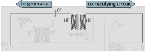
Firstly there is a conductive break in the form of capacitor C1 (and for the return section C2), which will only be crossed by an alternating (or pulsed) current; and secondly there is a conductive break by the horseshoe coil windings (see fig.4), which are mutually coupled to eachother through induction (through the iron or mumetal of the horseshoe) but are not directly connected and will, again, only pass an alternating (or pulsed) current between them.
So, while these two factors provide the isolation needed, at the same time they ensure that an alternating (or pulsed) current can pass between the electrostatic generator and the oscillating, rectifying, and transforming parts of the circuit.
It should also be noted that there is another reason for the horseshoe magnets being placed where they are with, as you will have no doubt noticed, two coil windings of the same number of turns (so they cannot be used as transformers). For they are correctly placed to act also as mutually-coupled iron-cored inductors, to act as chokes to compliment the UPR (upright) chokes situated to each side of the back column, on the way to the rectifier, this is to inhibit the current flow so as to prevent current being unnecessarily discharged in the rectifying process.
But here, possibly, between the feet of the horseshoes are the main reasons for using electrets instead of plain uncharged plastic blocks.
One – the four electrets in each horseshoe could be connected, all in the same direction, just as a one-way diode to allow one-way current flow (ie HP1 to HS1 toward the rectifier; and rectifier to HP2 to HS2 and back to the generator): or Two, which is more likely, that the electrets are placed inside the horseshoe feet in a full-wave rectifier configuration (see fig.6) so as to allow conduction of both POSITIVE and NEGATIVE pulses to be directed into an auxiliary part of the circuit, namely the base storage capacitor. ECG1 (EL1) transferring charge to one terminal of the base capacitor and ECG2 (EL2) transferring the opposite polarity to its other terminal so providing an accumulation of (DC) charge for its output terminals (see diagram below).
I suppose it would also make sense, while providing ‘electrodes’ for these electret blocks, as in the form of metal plates, that it would be advantageous to choose two such different metals so that when they touched they would pass current more easily in one direction than in the other. When the two are linked aluminium is positive while copper is negative – but it would be even better to use a zinc / copper combination (see Horseshoe Magnets page http://energy21.freeservers.com/orsshoe.htm ) and moreover, zinc more readily gives off electrons from its surface.
# NOTES:
– N1 – The list of different plastic materials to experiment with is extensive, aside from the usual plexiglas, perspex, acrylic, epoxy, and glasses, and teflon there is also; lucite, nylon, acetal, polycarbonate, pvc, abs, pet, uhmw pe, hdpe, polypropylene, peek, pes, pei, psu, ppo, ptfe, pvdf, asa, fep, ca, eva, pj, pp, psu, san, sb, to name but a few. All of which react differently when charged up, and all of which relate to the triboelectric charging principles – whereby some plastics are charged positive (donator) and some are negative (acceptor). For more information see “Handbook of Electrostatic Discharge Controls” by Bernard S. Matisoff (1986) pp16; “Understanding and Controlling Static Electricity” by G. Luttgens & M. Glor (1989) pp44; “Plastics for Electrical Insulation” by Paul F. Burns (1968) p50.
– N2 – See “Electrostatics And its Applications” by A.D. Moore (1973) is a very well researched book on electrets (p122 130) and electrostatic machines; “Handbook of Electrostatic Processes” by Jen-Shih Chang (1995) pp509 on electrets.
– N3 – The first person to make an electret was Mototaro Eguchi, see his “On the Permanent Electret” paper in “Philosophical Magazine” Vol 49 (1925) pp178.
– N4 – “How to Make an Electret” by C.L. Strong in “Scientific American” Vol 203 (Nov 1960) p202 210 is a practical description of how to make an electret using carnauba wax.
– N5 – “A Treatise on Electricity and Magnetism” by James C. Maxwell Vol 1 (1881) # 325 334. And see above for A.D. Moore (p122).
– N6 – See “Dielectrics” by P.J. Harrop (1972) p71 for dielectric absorption. Doping the dielectric with, for instance, paramagnetic particles will increase the amount of, and surface area of, the interfaces; which is one reason why their inclusion in a dielectric increases the ionising effect. But see the Patrick Flanagan Electron Field Generator page