### Mc Kay investigate Edwin Gray’s story, page 1: (page created for November 2007)
See also the HV Marx Generators page zpe_marx_generator.html, and the page Spark Gaps zpe_sparkgap.html
## Part 1: Enter … The Mallory Connection, Mark McKay, PE 3/2/06,’McKay3.pdf’, 13pages, 1,437kb, from files of the YahooGroup ‘alfenergy’
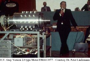
Consider the now classic 1977 photo (above) of Mr. E.V. Gray demonstrating his EMA6 motor to investors at the Sportsman Lodge in Burbank, CA. THis photo was taken by Tom Valentine, who wrote a series of informative articles about the EV GRAY saga. Dr. Peter Lindemann received this original film from Mr. Valentine to support Peter’s research for his book ‘The Free Energy Secrets of Cold Electricity’.
In a fruitful attempt to extract additional technical information from this historical photo Dr. Lindemann arranged to have if digitally enhanced. One of the goals of this effort was to decioher the writting on the large gray storage capacitor directly under the motor. It read:
MALLORY – Made in USA – Type TVC-606 – 5.0 MFD 5,000 VDC
Mallory is a well known name in the field of electronics. When one thinks of Mallory today they generally think of the premium large blue electrolytic filter capacitors that dominated the high end linear power supply market in the 70’s and 80’s. At its peak, the P.R. Mallory Company was a power house of US made electrical components. Not only did they make several lines of capacitors but they also made Battery Chargers, Resistors, Rheostats, Rectifiers, Switches, UHF Converters, Noise Filters, Soldering Iron Tips, and Special Television Components. Their 1955 Catalog was 60 pages long.
Mr. P.G. Mallory started out in 1916 with the invention of the Mercury Battery. By 1965 the company developed the well known Duracell Alkaline battery.
The North America Capacitor Company (NACC) is headquartered in Indianapolis, Indiana. Today, NACC continues to manufacture and market Mallory capacitors at its modern manufacturing and warehouse facilities located in Greencastle, Indiana and Glasgow, Kentucky.
Another important Mallory invention, very relative to the EV Gray technology, was the 1920’s development of the ‘Elkonode’, better known back then as simply the ‘vibrator’. Today this device is hardly known at all. In its time it served as a vital sub-system in early DC converters. These were used to raise the low voltage levels of storage batteries to the operating levels required by vacuum tubes, which was 200 to 500 VDC. This now forgotten electro-mechanical component was the functional equivalent of two push-pull power transistors in a modern switch-mode power supply. At the time, when it came to mobile elctronics there were two choices. 1/ A vibrator based power converter, or 2/ A heavy dynamo-motor base converter. For applications under 30 watts the vibrator approach was smaller, lighter, cheaper, and more efficient than the alternative. Therefore, the military had a serious interest in this technology, but it was in the mass market demand for small vacuum tube car radios where the real money was made.
The P.G. Mallory Co. almost completely dominated the top end power vibrator market for 40 years and was responsible for almost all of the performance improvements through the 40’s and 50’s. But, all good things must end. This lucrative product line came to a screeching halt in 1957 with the development of low voltage signal and power transistors. But Mallory still managed to keep a cutting edge in many of its other market areas for several years after that.
So it is no big surprise when one reads in the 1973 Scagnetti EV Gray article:
The Engine that Runs Itself, by Jack Scagnetti from ‘Probe The Unknown’ in June 1973.
‘Mallory Electric Corporation of Carson City, Nevada, has also made a major contribution toward the design of the electronic pulsing system.’
It’s all pretty obvious that Mr. Gray had a huge investment in Mallory type components. If is invention did become main stream then the Mallory Co. would have had first shot at a huge new automotive market. Each new vehicle would need between USD300-600 worth of rugged HV storage capacitors, not to mention an investment of twice that much for vibrator power converters or their equivalent solid state replacements, which Mallory made also.
It is real easy to see how Mr. Gray could have convinced a few executives at Mallory how it would be in their best interests to help him out financially, or at least provide him with a little hardware donation from their Vibrapack division in Irvine, CA. Mr. Grays impressive ‘hands on’ demonstrations were known to be very effective at convincing technical professionals that he was on to something big, providing that he was ever allowed the opportunity to make such presentation to a real decision maker. Most likely some inspired and insightful 3rd level staff person managed to fix him up with a pickup load of surplus vibrator converters that were, or would be, completely obsolete.
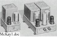
Examples of the P.R. Mallory line of ‘Vibrapacks’ (DC Converters) from 1955 Catalog.
All models have a 30 Watt power rating except the one on the far right which is rated 60 Watts.
But this story has an important twist in it …
The Mallory Company that gave Mr. Gray enough money to make mention of it in the above magazine article was not the P.G. Mallory and Company Inc. but the Mallory Electric Company of Carson City, Nevada, designers and manufacturers of a multitude of OEM and after-market automotive ignition systems.
Mr. Marion Mallory was the rare sort of independent individual who would start a company on Friday the 13th in February of 1925. He was a self-made inventor with a 4th grade education who was not only brilliant at his craft but also had what it takes to manage a business. It he ever met Mr. Gray face to face the two men would have had a lot in common, especially from a ‘hands-on’ creative energy standpoint. Mr. Malloy made his money in a variety of automotive, motor cycle and marine ignition systems. For years he was the main supplier to the Ford Motor Company for ignition distributors and their upgrades. He received about 30 US and 10 international patents for a multitude of significant improvements in ignition technology, both in electrical and mechanical systems. He was darn good at business, but his personal weakness was high performance auto racing. The market for race car parts is not very big, but the sctivity it supports is very addictive. Marion sponsored as many as three teams a year in the various classes of professional auto racing. It is also been said that Mr. Mallory looked for and hired like minded creative engineers and technicians. He also despised the union worker mentality that had become so adversarial in the Detroit area between the 50’s and 60’s.
Mr. Mallory finally got fed up with the stifling and counter-productive demands of the United Auto Workers Union. In a rare act of individualism he decided to make arrangements to move his entire company, lock, stock and ignition coils to Carson City, NV. At this time Marion was getting along in years and unfortunately never made the move. He died in 1968 at the age of 70. His son ‘Boot’ Mallory was then handed the reins of this privately held company. ‘Boot’ terminated all the Union labor and kept 10 of the most productive engineers and technicians who were willing to relocate to the new factory. This facility was opened in 1969. From all accounts the ‘heir apparent’ and only son was very motivated, technically competent, savvy at business, and like his father hopelessly addicted to high performance auto racing.
Given the timing of events it is most likely that Mr. Gray never met Marion Mallory. It is almost certain that the connection to the Mallory Company was entirely between Mr. Gray and ‘Boot’ Mallory. This was also helped by the fact these two men were about the same age with Mr. Gray being 5 years older.
For their entire business careers Marion and ‘Boot’ Mallory were always on the look out for improved ignition systems, both for good business practice and, of course, a desire to sport the fastest cars at the right track. Their knowledge base and field of experience covered all approaches to ignition system design, both in the electrical and mechanical areas. It is interesting to note that they developed and manufactures magneto systems as well as traditional distributor systems. Understand that these two technologies are vastly different to each other.
In the auto racing circles it has always been known that capacitive discharge ignitions system are far superior to the limitations of the standard Kettering induction sysstem, especially at high RPM. Dr. Tesla patented the first CD ignition system as early as 1898 but it was never produced because of serious design and component limitations. Marion Mallory and his engineers did get a working capacitive-discharge system finally connected to a race car engine in 1948. This first design was built employing a thyratron gas tube and vacuum-tube circuitry. As a result, it was costly, bulky, and unwiedly, not to mention fragile and economical unfeasible. But despite all of its failings the Capacitive Discharge Systems (CD) clearly showed its superior performance in the laboratory and on the track. Had it not been for the random and sudden failure of these alpha-test units (because of vibration) they might have still been used in professional auto racing, regardless of their unit cost.
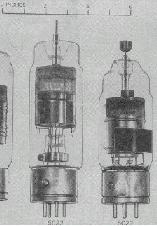
Glass Hydrogen Thyratrons of the 40’s. From ‘Pulse Generators’ Radiation Laboratory MIT 1948.
Two new tachnologies were needed to get CD systems off the ground.
1) Some method to boost the 6 or 12VDC storage battery voltage to the 400-500V range with an available current of at least 100mA (40-50Watts).
2) A component or technique that would replace the bulky, fragile, and power hungry thyratron that acted as the master timing control switch.
Both solutions came along about the same time. Power transistors became available to the aerospace industry in 1954. These allowed the development of early push-pull switched mode power supplies whose output were way beyond what a mechanical power vibrator could deliver (up to 90 Watts initially). Complete transistors converters were available to the hobbyist in early 1958. So we can assume that prototype power transistors were available to industry in about 1955.
See picture : Early advertisement for a 90Watt (Pulsed) Hobbyist 12V to 450V DC Converter. From ‘QST’ magazine January 1958. (Notice size reduction when compared to the 60W Vibrapack)
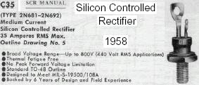
The second breakthrough came with the invention of the Thyristor or Silicon Controlled Rectifier (SCR) by Bell Labs in 1957. General Electric quickly bought the rights for this promising technology and wasted no time in bringing it into production. The manufacture of solid state power rectifiers and transistors was already well underway, so, building an SCR using the existing production equipment was a slam-dunk. According to the GE SCR Handbook 1964 3rd edition, the model C35 had already been in the field since 1958.
With these new solid state components at hand Marion & ‘Boot’ Mallory were off ans running. Their first beta-test race track CD ignition system was introduced in limited quantities in the fall of 1961. Their first after market production models did not reach distributors until 1964. It took 3 years of detailed development and waiting for the SCR market to settle down before deciding on a final product design. While the basic operating principles of a CD ignition circuit is straight forward getting a long-life circuit that will function well when exposed to the temperature, voltage, and vibration extremes is a different matter. At that time in our country’s industrial heritage new products were not generally rushed, half-baked, to the re-sellers because of some imaginary dead-line imposed by the bean-counters in the marketing department.
So, in the time frame of 1960 to 1970 where could Mr. Gray have gone when he needed some rare applied technical expertise on battery operated High Voltage pulse systems? The solution seems almost obvious.
We have no doubt that Mr. Gray and ‘Boot’ Mallory were on a first name basis. They may have aleady developed some kind of relationship while the company was still in Detroit, we don;t know when they first got together. We do know that Mr. Gray was provided with some significant venture capital along with the fruits of 10 or so years of proprietary field tested solid state CD technology.
It has been pointed out, by knowledgeable sources, that all of the Mallory’s after market ignition systems used power transistors for the 6-12V to 450V converter section. So, we wonder, why was Mr. Gray still using obsolete vibrator packs in 1973? ‘Boot’ would have certainly supplied Mr. Gray with the most modern equipment, along with the SCR and Ignition-Coil components in a small, self contained, custom engineered, and de-bugged package.
We suspect that ‘Boot’ did provide these complete transistorized CD systems and that Mr. Gray was eagerly looking forward to the reduced size, increased life time, and improved efficiencies that the new solid state devices promised. Especially after having to constantly fight with vibrators that kept burning out during his trial runs. But Radiant Energy (RF) operation has its own special challenges to deal with. One major engineering issue is what to do with the Electro Magnetic Pulse (EMP) like effect that happens when a RE circuit reaches a certain power level. If all that excess energy is not properly shunted to the system common (hopefully after doing some serious work) it escapes from the circuit conductors to charge every metal object within 20 feet or so of the generator. A multiple of blue-white sparks will erupt from every metallic object in a room, due to the induced high voltage. This is certainly an interesting light-show, with the lights turned off, but devastating to any near by transistor or IC that has any amount of wire connected to it. Transistors and IC’s that are stored in metalise protective bags or boxes seem to survive.
If this was the case, then we can imagine how disapointed Mr. Gray might have felt when his new transistorized converters started to fail, perhaps even catastrophically. Fortunately, and we really mean very fortunately, the SCRs were able to survive the RE onslaught. Had this not been the case the EV GRAY technology, because of the constant system failure, would have seriously fallen on its nose by 1965 and never have been able to produce the demonstrated power levels that we would so very much like to recreate.
Transistors fail because they are constructed with super thin base structures that are sensitive to moderate voltage differences. SCRs are constructed with thick silicon layers that are relatively more rugged. However, a poorly designed trigger circuit in an RE application will still destroy a heavy duty SCR, if proper gate transient protection methods are not employed. Because of this first hand experience Mr. Gray went on to install many over-voltage protection devices in his future circuits. This is very apparent in the dsign of the power supply shown in his Conversion Tube Patent #4,595,975.
It appears that Mr. Gray was forced to go back and use the failure prone obsolete vibrator packs that he started out with. Acording to the first patent these were used for the primary DC voltage conversion. We suspect that the engineers at Mallory were enlisted to help Mr. Gray marry the vibrator pack to the SCR system. The SCR addition did help solve the failure problem by reducing the arching current across the vibrator contacts. This is not a straight forward interface and it requires some experienced electronic know-how. The challenge is balancing the limited current capacity of the vibrator to the low impedance of the SCR storage capacitor.
Schematic Wiring Diagrams for two P.R. Mallory Vibrapacks, 60W model on left – 30W on right
Other researchers contend that Mr. Gray never intended to use transistors in the firat place. This is because one RE theory states that the non-classical process begins in the minute arcs formed during the making and breaking of the vibrator contacts. This technical issue is still open for debate and experimental verification.
However, we all agree that the SCR CD circuit is still a vital sub-system to the EV Gray technology, but it is not the whole story for a complete Over Unity (OU) process. We further believe that Mr. Gray didn’t disclose the kernel of his ‘secret’ to ‘Boot’ or any one else at the Mallory Electric Company. It would appear that ‘Boot’, because of his unique individualistic upbringing, respected Mr. Gray’s right to his own creations. ‘Boot’ was obviously far sighted enough to see some greater business potential in this venture, not to mention a whole new class of future racing machines. One main reason for this enlightened attitude was that ‘Boot’ didn’t have to contend with a short-sighted governing board of directors whose members were more worried about next quarters stock price than taking risky chances on age changing technologies.
The CD sub-system of the Gray motor was not disclosed in patent #3,890,548. Mr. Gray did mention the use of igniton coils in the patent text, but didn’t show them in the schematic diagram. The simplest solution to help protect his ‘secret’ was to just eliminate the CD sub-system from the schematic. Since Mr. Gray was only attempting to disclose a new type of pulse motor in this first patent. The omission of a ‘minor’ power supply ‘feature’ was not going to mean anything to the patent reviewers. But, the devil is in the details, especially when attempting to reconstruct this lost technology 30 years later.
There is a good possibility that Mr. Gray was returning a favor to ‘Boot’ by not disclosing the proprietary CD circuit designs. They very well could have had a gentlemen’s agreement and a joint venture on this issue. ‘Boot’ didn’t need to know Mr. Gray’s Free Energy ‘Secret’. His high margin piece of the action was locked in because each new EV Gray motor would need 18 or more complete CD power supplies, inlcuding the patented constructin details of the Mallory ignition coils. Mr. Gray’s success was going to be ‘Boot’ Mallory’s success – BIG TIME. A classic win-win situation. It’s no wonder that ‘Boot’ willingly made out checks to this unknown and un-educated inventor from California. While the P.R. Mallory Company was unknowingly going to reap some benefit from this breakthrough the Mallory Electric Company was going to hit the jack pot.
As a purely speculative observation, it may have been ‘Boot’ Mallory who clued Mr. Gray in on how to write patents and attempt to protect one’s intellectual property from the big business lawyers. What to show and what not to show, what to draw and what not to draw and what to say the rest of the time. With this technology it was going to be a feeding frenzy as soon before the first beta-test hit the street and ‘Boot’ knew it. Mr Gray probably received a life time of inside information on how to keep secrets, make money, and cover one’s assets from a man who had been there and seen how big business really works.
We all know that Mr. Gray suffered a major setback when his research facility was raided in 1974 by the agents of the Los Angeles District Attorneys Office for suspected securities fraud. But by 1977 as shown in the photo above, Mr. Gray had recovered enough to receive his first patent, build, debug and demonstrate his second generation motor. What is not generally known, in Free Energy circles, is that Mr. Gray suffered a far greater loss when ‘Boot’ Mallory was killed in a car wreck in 1978 at the age of 48. He was always known to be somewhat of a lead foot.
Gone was the financial, technical and moral support. As far as we can observe it appears that the EV Gray motor didn’t develop significantly much beyond the EMA6 model (above). The surviving Mallory women sold the company to Super Shops of Irvine, Califormis in 1979. Mr. Gray continued to seek a proper level of investment capital so that he could control and manufacture his fuel-less motors in-house. He also improved on his popping-coil demonstration and updated it to a continuous process that hinted at anti-gravity possibilities, very impressive. It has also been rumored that Mr. Gray almost did collect enough money to begin production.
Unfortunately, we also know that ten years later Mr Gray died under un-resolved circumstances in Sparks, NV in April 1989. Sparks is just East of Reno, NV, which is about 50 miles North of Carson City. Some researchers contend that the main reason why Mr Gray established one of his multiple laboratories in this town was because of the invaluable technical experience of some of the retired Mallory technicians still living in the area.
…
Note: This document is one in a series produced by Mr. McKay as part of his investigation of the work of Edwin Gray senior and he invites readers to contact him if they have any constructive comments or queries concerning the work of Mr. Gray.
## Part 2: Taking a closer Look at the Demonstration Equipment, Mark McKay, PE Oct. 24 2006, ‘McKay2.pdf’, 7pages, 499kb, from files of the YahooGroup ‘alfenergy’
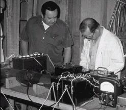
This is the classic photo of E.V. Gray’s ‘Popping Coil’ Demonstration apparatus. This can be found on Peter Lindemann’s website. This photo was taken by Tom Valentine in 1973. Mr. Gray is the man in the center and Fritz Lens (his new father-in-law) is on the right. The man on the left is unidentified (most likely Richard Hackenburger VP of Engineering).
For years, about all one could say about this phot was that there was a fair amount of equipment involved in these demonstrations. The energy source appears to be a common large automotive 12 volt battery. Identifiable components are the custom made air transformer and the Triplett 620-A multimeter, all the rest of the technical detail is hidden by the black Plexiglas instrument boxes. By itself this phot does not yield much information.
In 2004 a former E.V. Gray investor came forth and presented Peter Limdemann and John Bedini with a period collection of historical snapshots. Five of these photos were of the same apparatus that was shwon to Mr. Valentine in the above photo. The location was different, but the equipment and layout appears to be the same. It is assumed that these new investor photos were taken at Mr. Gray’s shop in Van Nuys, CA. THese photos were developed in January and June of 1974 so they could have been taken within a few months of the Valentine 1973 photo. By obseving these photos some additional technical information about this novel technology can be extracted.
The investor photos:

This is a nice shot of the whole demonstration apparatus from one end of the table showing the supply battery, two popping coils and an end view of the air transformer. Despite the limited focus, this photo shows that the popping coils are connected in parrallel since the white leads on the left are both terminated on the negative terminal of the battery. Also connected to the battery is a component that appears to be an analog metering current shunt – a low value high current resistor device. However, there is no meter connected to this component as there would be in a normal application. This suggest that it is being used simply as a low value current limiting resistor. It is doubtful that this component was ever intended to be used in a metering capacity. Its output would have been a very short voltage pulse that could not be recorded or observedon any of the test instrumentation shown in any of these photos.
It is believed that the two black leads on the right of the air transformer are disconnected and hanging straight down to the floor. Compare this situation to the Tom Valentine photo where these heavy black leads are connected to two of the black boxes.
There appears to be four black wires connected to the right side of the electromagnets. The two larger black wires are thought to connect to the wipper of the DPST knife switch. It is not known for sure where the small remaining black wires connect, but most likely to an additional set of electromagnets parked under the air transformer as shown in photo #013B. If so, then there probalby was an accompanying demonstration that showed what would happen if additional load was added to the circuit.
This photo is taken at the same location some time earlier where the circumstances were slightly different. The small white table and its attending equipment that is shown in the future June 74 photos are not preset. This phot (Jan 74) was developped 6 months before photo #013C. The equipment on the large table seems to be in the same place at the other end (right side) of the table.
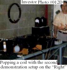
It is proposed that this total assembly of ‘Black Boxes’ (a dozen or more subsystems) actually supports two different and independant demonstrations, a ‘popping’ coil’ demo on the left and another ‘popping coil’ demo on the right. The photos available allow for a better technical analysis of the demonstration equipment on the left side of the table. It is unknown as to what the actual differencies between these two demonstrations were, however it is apparent that the coils being popped have obvious size differences. In photo #012D the coil in mid air is about twice the size of the electromagnets shown at the other end of the table in photo #013C. The Tom Valentine photo shows a set of electromagnets (at rest in the lower right hand corner) that are at least four times the size of the coils used for the demonstration that was set up on the left side of the table. However, the launched coil shown above is not the same (being 50% smaller) as the coil shown in the Tom Valentine photograph, even though it is being powered by the same equipment.
It is thought that the demo on the right had something to do with a higher power level or a more advanced method of energy recovery. Most likely, the demo on the left was intended to make the initial technical introduction to the basic idea of a repulsion motor concept, while the demo on the right had some important engineering advancement to display.
Phot #012D is dark but it helps shows that the two white wires from the DPST knife switch for the left demo connect to the two equal size boxes in the middle of the table, one wire per box.
This June 1974 photo is a nice over view of the ‘left’ demonstration equipment. The major issue here is the additional equipment on the small white table. Here we see some identifiable items, a neon transformer, a 2kW Variac autotransformer, a cassette tape recorder and a barrier type terminal strip. The question is: What is this extra stuff for?
It appears that this setup is a variation from the normal equipment demonstration as seen in the Tom Valentine photo. It seems that the Air Transformer is disconnected from the system ans has been replaced by the power provided by the equipment on the white table. Most likely this was an attempt to demonstrate that AC line power could be converted to ‘Cold Electricity’. It is important to note the variations in this particular circuit layout as it provides some clues as to the function of the various Black Boxes.
Firat, notice that the two white wires that go to the DPST knife switch have now been connected to one terminal of the Black Box, while a red jumper connects to the white wires’ previous connection point. Compare this to how these white wires are connected in the Tom Valentine photo.
It is not all together clear how the neon transformer and Autotransformer are connected but a standard approach would be to have the Variac control the input line voltage to the Neon transformer. This Variac has the ability to increase its output voltage by 25% above its input. If the Neon transformer were a common 15kV 30mA unit then the RMS output voltage could have benn adjusted to a maximum of 18 kV. This is comparable to the output of an auto ignition coil. The peak DC voltage potential would have been about 25kV. However it is unlikely they were operating at this high of voltage for very long because of the size, layout and construction of the temporary conductors.
Since a single pair of conductors (yellow and black jumpers) drop below the top of the white table it is proposed that there is a high voltage diode stack underneath the table on a shelf that is operating in half-wave mode. Had full-wave mode been used then four wires would be seen leaving the top of the table (which is still a possibility).
The utilization of DC pulses is very clear in the Gray motor patent. It has often ben wondered why Mr. Gray didn’t use full-wave rectification in his power supply to take advantage of the increased efficiency. Apparently this equipement does not have a taste for straight DC voltage. This concept is reinforced by the use of the half-wave rectification power supply shown in photo #013B. This situation supports the idea that Mr. Gray may have had capacitors connected in series, without equalization resistors, thus pulsating DC would have been needed to charge them.
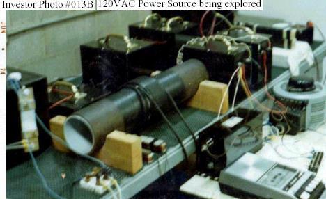
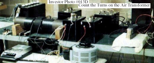
Phot #013B shows the best view of the demonstration equipment for the ‘right side’ demonstration. It seems to be composed of five Black Boxes, two small ones, two large ones, and one small flat one. If a knife switch was used to launch the popping coil it is not visible in these photos. An air transformer seems to be missing from this equipment collection. However, consider the cylindrical object seen under the large table in photos #012D and #013D. This is about the size of a gallon paint can and has a yellow tape on top. These balck wires (and possibly a fourth) can be seen leading to this device. It is proposed that this is the air transformer used for this equipment. It has a larger diameter (8″) than the air transformer that is used for the ‘Left side’ demonstration (4″). It is believed that the automotive battery seen at the left end of the large table is the prime source of power for both demonstrations. A Tiplett 620-A multimeter can be seen laying down on the far right of the table.
Examine the air transformer in its disconnected configuration. Notice how the two black conductors roll off the coil to the floor. This can only be achieved with two separate layers. The nearest conductor is part of the first layer. From this observation the relative polarity of the air transformer can be determined.
The core of the air transformer appears to be about 4″ in diameter, when compared to the 2″x4″ support blocks. It appears to be of a dual layer construction like one kind of pipe was slipped over another. The inner pipe resembles gray electrical PVC, but thinner (could be schedule 20 pipe). The outer pipe is a dark brown material that is not a common modern construction material. It is closed to an older fiber-composite material that was used for sewer pipe in the 50’s. Why the need for two nested cores? Is the dielectric breakdown of the core that big an issue for such a small air transformer? The insulation strenght of the (assumed) spark plug wire is near 50kV and should be plenty for the operating voltages expected. In addition there appears to be a hefty layer of electrical black tape between the core and the heavy windings.
It has been proposed that the black tape covers a single layer of #16 AWG magnet wire that forms a winding 3-4 times longer then the observed spark plug wire ‘primaries’. This feature (if it exists) is considered to be an additional energy recovery subsystem.
This photo is to fuzzy to axtract much additional detail, (as compared to photo #013C) however the 35 mm camera that is being held by the gentleman on the right is clear enough. Also, note the Flash Cube snapshot camera sitting beside the autotransformer. Cameras are in abundance in this portrait. This suggests that this particular collection of photos (June 74) were the result of a planned event where selected investors were allowed take all the snapshots they wanted. It is believed that this was a rare event. Therefore we can be assured that the equipment displayed at this time had been personally sanitized by Mr. Gray to insure that none of the essentials of his ‘Secret’ would be disclosed.
The well dressed bentleman, on the left, appears to be holding another cassette tape recorder with a black plastic microphone being held in his fingers.
This is about the best photo available showing the overall layout of both coil popping demonstrations. A lot of the essential details are hidden in this presentation but some of the subsystem interconnections can be determined.
The lower shelf of the white table displays what appears to be a HV ‘door knob’ capacitor that is connected to Yellow and Black jumoers. It is more likely that this is a HV diode.
End of this 7 pages document.
## Parts 4, 5 and 6 of Mark McKay investigation are on the other ‘McKay’ page, see menu on top, because of numerous pictures.
## Part 7: Edwin Vincent Gray (1925-1989), ‘McKay3.pdf’, 4pages, 28kb, from files of the YahooGroup ‘alfenergy’
## Extracts from file ‘McKay7.pdf’: Gray’s Biography
…
Towards the end of 1969, Gray terminated his auto-body business, never to practice it again. He sold 2/3 of the Van Nuys building to his nephew and re-outfitted the remaining portion to build and promote his next business enterprise. Somehow, Ed Gray had made a sudden and dramatic shift from the auto-body business to an independant inventor with an extraordinary technology, with hardly any previous background in electronics.
Members of his family are still baffled by the quick transition. Some say their father was occasionally stuck with flashes of profound inspiration. Other researchers say that Gray must have been working secretly on the motors for years, but family members dispute this. Gray himself told one of his partners that he received this information from a Russian immigrant named Dr. Popov, who had gotten it from Nikola Tesla. But again, family members claim no knowledge of these supposed events. While there are similarities between Gray’s technology from 1970 and Tesla’s ‘Method of Conversion’ technology from 1893, there is no known lineage to trace the connection between these two processes. No one ever saw Gray studying the work of Tesla, or running any preliminary experiments. No one who is still alive, who was associated with these events, knows where the technology came from or how it developed.
In 1971, Gray formed a limited partnership named EVGRAY Enterprises, Ltd. By 1972, Gray had gathered enough investment and development expertise to build a 10 HP prototype motor. This unit was submitted to Crosby Research Laboratories for evaluation at Cal-Tech. Crosby Research Institute was owned by Bing Crosby and run by his brother, Larry Crosby. This motor demonstrated an output of 10HP (1460Watts of mechanical energy) for the extremely low electrical input of 26.8Watts. This is an apparent energy gain of 278 times the input! This left the Cal-Tech scientists very uncomfortable. The report states the motor operated at ‘over 99% efficiency’, but the rest of the data is a little confusing.
On the strength of this report, Bing Crosby came on board as a major investor. So did ‘Boot’ Mallory, of the Mallory Electric Company, who made the high voltage ignition coils used in Gray’s circuits. By early 1973, EVGRAY Enterprises, Inc. had completed a 100HP prototype motor called the EMA4-E2. Fifteen private investors were now involved. Ed Gray also received a ‘Certificate of Merit’ from Ronald Reagan, the Governor of California, during this period.
By the summer of 1973, Gray was doing demonstrations of his technology and receiving some very positive press. Later that year, Gray teamed up with automobile designer Paul M. Lewis, to build the firat fuel-less, electric car in America. But trouble was brewing when a disgruntled ex-employee made a series of unfounded complaints to the local authorities.
On July 22, 1974, the Los Angeles District Attorney’s Office raided the office and shop of EVGRAY Enterprises, and confiscated all of their business records and working prototypes. For 8 months, the DA tried to get Gray’s stockholders to file charges against him, but none would. Since he only had 15 investors, many of the SEC regulations did not apply. By March 1976, Gray pleaded guilty to two minor SEC violations, was fined, and the case closed. After this investigation ended, the DA’s office never returned any of his working prototypes.
In spite of these troubles, a number of good things were happening. His first USPatent, on the motor design, issued in June of 1975, and in February 1976, gray was nominated for ‘Inventor of the Year’ by the Los Angeles Patent Attorney’s Association, for ‘discovering and proving a new form of electric power’. Despite this support, Gray kept a much lower profile after this time.
But there was also other setbacks. Paul Lewis pulled out of his deal with Gray in 1975 when Gray couldn’t deliver a production motor for Lewis’s Fascination car. Gray made a last ditch effort to secure the needed capital to get his motor into production by calling a press conference in 1976 and demonstrating his nearly complete, second generation 100HP motor, the EMA-6. Unfortunately, this event didn’t secure any additional funds for the company. Shortly thereafter, Bing Crosby died in 1977, followed by ‘Boot’ Mallory in 1978. This left Gray without his two strongest supporters.
In 1979 Gray reorganized himself into ZETEX, Inc. and EVGRAY Enterprises, Inc. ceased to exist. In the process of this corporate restructuring, all of his earlier stockholders lost all of their money. Gray then moved his development operations to Kalona, Iowa where new investors were supporting his research. This working relationship also failed when these new partners attempted a hostile take over. In a sudden midnight flight, in the middle of winter, Gray loaded up the technology with all his belongings and headed to San Diego, CA where he stayed 18 months.
In 1982,he relocated his operations to Canyon Country, California where he hired three assistants to help build several large demonstration carts. After a year of work, Gray got suspicious of the loyalty of his employees. He abruptly fired all of them when they reported for work one morning. He then moved to a second location in Canyon Country and continued with the construction until early 1984. Later that year, he moved his operation back to Las Vegas where he stayed till the spring of 1985. In the summer of that year, he moved to the almost abandoned town of Council, ID (population of 816), where his oldest son ‘Eddie’ has settled down.
In Council, Gray finished up the construction of five different motor prototypes and several other kinds of demonstration equipment. He then began to produce promotional videos and invited local TV stations to report on his work. Gray then sought out the services of a Wild Cat oil exploration lawyer and found Mr. Joe Gordon of Texas doing work in Montana. The two men formed a partnership under Mr. Gordon’s established business Western Oil. They also established a branch holding company in the Cayman Islands from which to sell stock in the new venture. Gray decided to move again, this time to Grand Prairie, Texas to improve his exposure to international investors.
On the strength of his video alone, the Cayman Island operation was selling stock and raising capital quickly. Interested investors from Israel convinced Gray to spend two weeks in the Holy Land where a series of emotional group negociations took place. An agreement was never reached. They conceded that the technology held a lot of promise, but it was not mature enough to be immediately employed on the battlefield. In addition Gray insisted on maintaining a controlling interest in what ever deal was cut. For whatever reasons, Gray came back with a much different attitude.
Meanwhile the agents who had been selling his stock in the Cayman Islands decided to give themselves large comissions, plus whatever other funds they had control of, and quickly move to Israel themselves. Apparently, they had also oversold the original stock issue by about three times.
Feeling swindled himself, Gray made a final, desperate attempt to get proper recogniton for his achievements. He actually wrote letters to every member of Congress, Senators and Representatives, as well as to hte President, Vice President, and every member of the Cabinet, offering the US Goverment his technology for Reagan’s ‘Star Wars’ program. Remarkably, in response to this letter writing campaign, Gray did not receive a single reply or even an aknowledgment!
In 1987, a person named Reznor Orr presented himself, claiming to be a ‘Government Contact’. Mr. Orr first made straightforward offers to buy all of Gray’s technology outright for a modest price. These intial proposals did not meet with Gray’s approval, and he turned them all down. At about this time, Gray’s income stream from the Cayman Islands stopped. Mr. Orr’s next offers were much less friendly, and mixed with certain veiled threats. When Mr. Orr left town, ‘to let Mr. Gray think about it’, Gray realized he had a serious problem. Out of money and under threat, he quickly held a massive liquidation sale, including personal belongings and family furniture he had had for years. Only the equipment and materials he could stuff into his Ford F-700 box van were spared. Gray drove to Portland, Oregon and hid out for six months.
Some time during 1987 – 1988, Gray became ill with a serious case of pneumonia and was hospitalized. He had been a heavy smoker all his life. He never fully recovered from this illness and required Oxygen from this point on. His reduced lung capacity made it much more difficult to continue his work.
From Portland he moved to Sparks, Nevada. Gray rented a combination living quarters and shop space in a light industrial area. He unloaded his truck and began to disassemble all of his demonstration carts. He was living with Dorothy McKellips at the time who claims that Gray still did experiments during the day but in the evening all the components were once again taken apart and mixed with ohter parts. Early, one morning in April of 1989, about 2:00 am, somebody suddenly started banging hard on one of the shop windows. Gray, in his compromised health condition, got out his gun and went down stairs to frighten off the intruder with a warning shot. The gun failed to fire. A few minutes later, Dorothy found Ed on the floor. It is presumed that the resulting stress caused Gray to suffer a fatal heart attack, although the exact cause of death was never determined. He was 64. The identity of the late night visitor is not known.
Gray’s oldest son ‘Eddie’ flew to Sparks, Nevada to identify his father’s body. Later, he spent several months attempting to help a Kansas group recover the technology. But, Dorothy would not release any of Gray’s equipment until she had received a large payment for herself. The Kansas group then got a court order to take possession of the technology. But the document was poorly worded and did not define exactly what ‘technology’ really meant. The order did state that they had rights to all of the motors. Dorothy caught this fact and gave them just the bare motors, keeping all the power converters and other things in her possession. Dorothy then decided to have the last laugh before this looming legal battle could escalate much further. She had all the remaining equipment, videos, parts, drawings, and laboratory notes hauled away and dumped in the local land fill. Apparently none of the remaining systems that the Kansas group had on hand were complete enough to reconstruct. Meanwhile, the remaining millions of dollars of investor capital in the Cayman Islands bank account were tainted by the fraud of the over-sale of the stock. Ultimately, these funds were either confiscated by the local government in fines or simply swallowed by the bank, since no one could withdraw the funds without being arrested.
[This account of the life and times of Edwin Vincent Gray was compiled by Mark McKay, of Spokane, Washington, after numerous interviews with a number of Ed Gray’s surviving children. This account is an attempt to piece together the most accurate retelling of Ed Gray’s story ever made available to the public. Many of the details in this account are in direct contradiction of earlier accounts as reported in the newspaper clippings from the 1970’s. These earlier accounts should now be considered to be in error.]