Page created June 2007
20 Bedini-Bearden Years ‘Free Energy Generation’
Extracts from http://www.icehouse.net/john34/bedinibearden.html
Special thanks to all the groups who kept the faith.
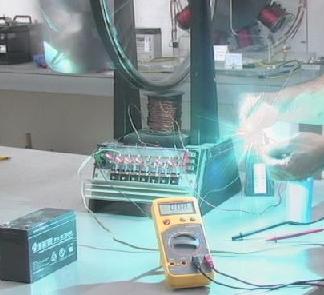
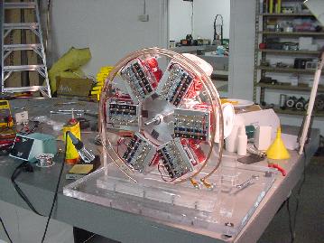
John Bedini discharging the radiant energy from the storage capacitors.
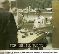
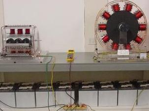
Tom Bearden John Bedini during a TUV test
Running load bank 2000 watts for 10 hours continous
TUV Test: BATTERY TEST FOR THE BEDINI MOTOR GENERATOR
DATE : OCTOBER 13, 2000 ; BATTERY TEST SEQUENCE:
One lead acid gel-cell (12 volts, 450 milliamps) is being utilized as the primary source fully charged at 12.5 volts
Three (3) lead acid gel-cell batteries (12 volt, 450 milliamps) strapped in parallel are being used as the charge destination. The batteries are discharged to 10 volts for the test purposes.
Test #1 starts at 10:45 AM utilizing primary battery fully charged at 12.5 volts charging three (3) destination batteries paralleled. The destination batteries reach a charge capacity of 14 volts at 11:20 AM.
The destination batteries are then discharged to 10 volts under working load to prepare for Test #2.
Test #2 starts at 11:25 AM utilizing primary battery measured at 11.5 volts. Charging three (3) destination batteries paralleled. The destination batteries reach a charge capacity of 14 volts at 12:50 PM.
The destination batteries are then discharged to 10 volts under working load to prepare for Test #3.
Test #3 starts at 1:00 PM utilizing primary battery measured at 10.5 volts. Charging three (3) destination batteries paralleled. The destination batteries reach a charge capacity of 14 volts at 1:40 PM.
The destination batteries are then discharged to 10 volts under working load to prepare for Test #4.
Test #4 starts at 2:05 PM utilizing primary battery measured at 9.5 volts. Charging three (3) destination batteries paralleled. The destination batteries reach a charge capacity of 13 volts at 2:40 PM. The primary battery is now discharged to 9 volts under working load and unable to further run the
TOTAL BATTERIES CHARGED:
12 lead acid gel-cell batteries (12 volts, 450 milliamps each). This ratio is a 12 to 1 charging factor. The motor operation (work) being performed as this was done is not included as an additional factor in this test.
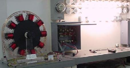
Bedini Simple Monopole Motor Generator:
Called ‘School Girl Motor’, because:
Bedini Simple Science Fair motor – 03/08/00
http://www.keelynet.com/bedmot/bedmot.htm
Jerry,
Here is a little girl that I talked to about a motor and she built it with a little help on the phone, it generates power and runs at 4000 rpm. Here is the MPG of all the since fair awards she took with one of My Motors. Still plugging away through schools now with the kids.
John
For more details see also Patric Kelly pdf file ‘D3’ : http://panacea-bocaf.org/files/patrickkelly/D3.pdf
US Patent# 6,545,444,and US2003/0117111A1
Now granted. Extracts from http://www.icehouse.net/john34/index100.htm
I have set up this page so you may review what has been going on in the past three years. We are talking only about the mono pole motor.
In the beginning of this conquest, I posted the plans to Keelynet on the “school girl motor“. I know that several of you on Keelynet tried very hard to build this motor, but I said in the beginning, just build the motor the way I said to do it. In short, do not change anything until you have something working!!!! There is a learning process here for those who built this motor the way I said to do it (about ten people). I did not say to hook meters all over the machine, I just said make it run first and then move to the next step. The work on this little model was very important to get an understanding of what the energy was and how it worked, and how you would trigger it in the end. Also at the same time, Tom Bearden went out of his way to write what my process was with my permission and E-Mailed it to Jerry Decker at Keelynet. What ever happened to that paper, I don’t know, but if you did not understand the paper you did not understand the motor/ energizer. All along Keelynet was given the information.
The US Patent office made me change the name of this device to fit into a category of motor generators. I was very lucky that they let me keep the mono pole part of it. The next fight with the Patent Office was the timing of the machine and how this device charged it’s batteries, but we worked this out (with a few word changes by them).
… (The problem was the test equipment would not read the energy flow to the batteries even though they were charging). My “coke formula” was kept out of the patent by the Patent examiner changing words in the text . (new speak). To over come this I broke the machine into three patents, which cost my company three times the amount.
DR. Peter Lindemann’s Motors, Open Letter to KeelyNet
As you know, I have been working with John Bedini for the last two and a half years. …
… With magnets on either side of the coil, I could make the machine act more like a generator, or more like a motor, or more like a transformer, depending on the set-up. After exhaustive tests, here are the results:
– 1 . When the machine is configured to function as a generator, it slows down when delivering power, it charges the capacitor poorly, and it draws more power from the source battery.
– 2 . When the machine is configured to function as a transformer, again, it slows down when delivering power, charges the capacitor to the voltage set by the windings ratio, and draws more power from the source battery.
– 3 . But, when both the transformer action and generator action are suppressed, the motor torque is maximized, the speed is maximized, the input power is minimized, and the capacitor charges quickly to voltages up to 30 times the input voltage on a one-to-one windings ratio.
… Teslas US Patent #695,958 clearly shows radiant energy circuits designed to run INDUCTIVE loads. Grays US Patent #4,595,975 shows radiant energy, again, driving INDUCTIVE loads. John Bedini has now moved the science of radiant energy one step farther by discovering how radiant energy can be captured in CHEMICAL loads, such as the electrolyte of a battery!
When radiant energy is properly applied to a battery electrolyte, the battery undergoes a series of changes that restores its potential AND lowers its internal impedance. This restores the battery to the condition generally referred to as “charged.” What is so astonishing is that it does this without the need to force the electrons from the positive plate back to the negative plate through an external circuit. Using Johns simple, patented inductively coupled radiant oscillators, and his patented switching techniques, the amount of electricity it takes to produce the radiant energy is very low, and the effect of the radiant energy on the receiving battery is very high. The source battery and the secondary battery being charged are NEVER directly connected to each other. There is no “closed loop!”
John and I have run tests with prototype, solid-state, radiant chargers that draw ONE WATT (12 volts @ 80ma) from the source battery and can charge a 7 amp-hour gel-cell battery from 10.5 volts (fully discharged) up to 14 volts in under one hour (3600 joules). This newly charged battery is then discharged by being connected to a sine-wave inverter and running a 100 watt light bulb for 40 minutes (240,000 joules). After discharge, it can be charged back to full again by the one watt charger in about an hour. The COP of the system is very high. The apparent efficiency of this test is COP>60! Even John and I question the math when it is this high. Never the less, we have run dozens of these tests with the COP>20. Different batteries behave differently with different charger configurations.
… Jerry, I am telling you this because I think you should recognize by now that there have been MULTIPLE, independent verifications of Johns discoveries, and that it is TRUE, and VERY GOOD NEWS! It has taken a huge effort to understand how the energy behaves in these circuits, and there is still a great deal to learn. You now have the reports from Harlan, Roamer, me and others. We have made the effort to learn what John has been reporting and succeeded. Others may have failed, but we have not failed. I am reminded of the fact that learned professors were filling chalk boards with equations “proving” that heavier-than-air flight was impossible more than two years AFTER the Wright Brothers flight at Kitty Hawk. In that scenario, the score turned out: Bike Mechanics 1, College Professors 0.
Please post this to the E-Scribe List. Sincerely, Peter Lindemann
… Their is one thing we should get straight right now, the dimensions of the coil are not important. The resistance of the coil is not important, the windings are not important, the magnets are not important. None of these things mean anything. All of you are wasting your good earned money on neo- magnets, dime store magnets will do just fine stacked together. There is no secret to this machine, it’s the process and the switching that’s important!!!!! I have never counted one winding when I was making these motors with Peter, I’m not saying one turn of wire will work because it won’t, again what is important is, THE PROCESS AND HOW YOU COLLECT IT AND SWITCH IT.
Why are you all thinking that it makes a difference in how the coil is wound, here is a number for you 500 turns number 23 tri-filer wound wire, see no step up no step down, just 1- to -1 ,welding rod for the core, roller-skate wheel, all north poles out, 2n3055 TO-3 case Junk but better, Do not use TIP 3055 it’s just real junk , 330 ohms base resistor, 1N914 diode, hooked up the way I said. that’s it. This makes your mechanical inductive coupled oscillator no big deal. By the way you are right about the terminology, we are babies at this to, just trying to (DEAD MAN FUSE IT).
Nature does not care what the coil looks like. OH forgot the 1kv diode bridge on the third winding, and a 10Uf 500 volt cap, be careful you will fly across the room. I said I broke the machine into three patents, third patent, use the bottom half of switcher only. Do we all get it now?, By the way this is a limited machine to just study the radiant current to the battery. Thomas Bearden has defined it!!! “Everything in nature is simple this is the most complicated to the human mind, let’s keep it simple”.
Most of the problems with what you are doing is, the magnets, using a bolt for the core is not right, I said cut welding rod and you are not selecting the correct resistor for the base current for this mechanical oscillator. Save your money you do not want to use NEO-MAGNETS, just use radio shack cheap magnets!!!!
WHY?
This motor energizer is a mechanical oscillator whose speed depends on the lowest amount of current you can put into the coil. If you apply too much current, you cause the transistor to cross conduct (known as cross conduction current). When you do this, the semiconductor over heats, because the current to the transistor stays on and the mechanical oscillator runs slow.You cause the same thing to happen by using NEO-MAGNETS.
Once the mechanical oscillator is running , YOU MUST ADJUST THE BASE RESISTOR TO THE HIGHEST VALUE that gives you the highest speed with the lowest current draw. The more magnets you get around the wheel the better the collection process will be. The magnets can not be too close together and must be spaced evenly around the wheel. You can find the right magnets at Radio Shack or a hardware store.
For the coil, just use an old solder roll or a bobbin you get wire on, cut and fill the center hole with .030 welding rod . This works really well.
Dual Battery Charger:
A Gift from John Bedini, The Dual Battery Motor/Generator,
http://theverylastpageoftheinternet.com/ElectromagneticDev/bedini/bedindualbatteryi.htm
Don
I think you should put something in place of a blank page. This is up to you I’m not going to put this on my pages. I’m just tired of answering questions about the motor to people that can not build it anyway, better sometimes that someone does it for them like yourself, but I will pass along this information to you, these two go together, the motor you are looking at is much bigger then the motors you are building. this motor runs on two watts and keeps all the secondary batteries charged, theCapacitors are 1 farad each, three in series for a total of 333,000 uf they are about 2 volts over the batteries the battery impedance is about .00023 Ohms it’s quiet a bit when these are pulsed, if the other patents issue next month, they explain you only need two volts over the battery, so do some experiments with your motor by making the cap’s larger like say 5000uf to 10000uf and watch the battery charge.
John Bedini
See also: Bedini Advanced Motor – 06/08/01
http://www.keelynet.com/bedmot/advmotor.htm no details will be provided until patent is granted …
The SG Project
http://www.icehouse.net/john34/kron.html
Solderingswitching circuits to the coils, mounting buss bars.
John Bedini and Peter Lindemann’s Medium and Large Motor-Energizer Project
http://www.freeenergynews.com/Directory/Inventors/JohnBedini/SG/Feb2005/index.html
Bedini team explains what they have been up to, and discuss what the Bedini SG was/is designed to accomplish as a teaching tool on the way to more advanced energy tapping technologies.Discuss new medium and large motor-energizers. Using 24-V 1600 Ah batteries.Lighting 1000 Watt array of bulbs.
The following are excerpts taken from posts made by John and Peter to the Bedini SG discussion list http://groups.yahoo.com/group/bedini_sg/messages , which is supplemental to the Bedini SG project at PESWiki http://peswiki.com/index.php/Directory:Bedini_SG .Personal aspects have been removed from the dialogue to keep it to science.
For FULL DETAILS, PARTS and SCHEMATICS to reproduce Bedini’s Motor,
go and the pages of ERWIN:
– Erwin’s Workshop http://www.fight-4-truth.com/Work%20Shop.html
– My First SG Replication. Last update of this section: Feb. 4, 07 http://www.fight-4-truth.com/Replication.html
… This next SSG Bedini/Cole N-Pole Motor of course is my pride and joy, it is a big leap in thesuccess of my Bedini technology research. There is real bronco performance in the Bedini designs. I am very happy I got into it, I learned a lot already in a very short time and especially in a field I was totally ignorant in. This knowledge gained will make me more flexible in my approach for alternative power.
– My First SG Replication, Page 2 http://www.fight-4-truth.com/Replication%20II.html
– Schemtaics Illustrated. Last update of this section: April 6. 07 http://www.fight-4-truth.com/Schematics.html
Circuit Schematics with little intro. and how I ended up in the Bedini Circuit:
Most folks who have little experience in electronics aren’t able to read schematics let alone soldering components onto a circuit board to get a working gadget. I am one of them. I am a Swiss Tool and Die Maker, have therefor little knowledge in electronics. Looking at a schematic, it is evident that applying the proper mechanical and practical technique one can’t possibly work it correctly without experience and proper schooling. Soldering components through a board did not work for me. I remember John’s comment, the closer everything is soldered together, the better it works. Not until I omitted the board did it finally work. Once I figured out by trial and error, how to solder up the John Bedini Circuit, I made drawings for easy visualizing of the different soldering joints and component arrangements. …
… By the way, you can spare yourself a big disappointment in building Tesla Cone Transformers, without first doctoring with high pressure DC-magnetos and big capacitors, disrupters, high frequency, twin conductors, unidirectional interrupted high-impulse-charge-discharge ratespark discharges!! Impulses must be short and precise in their successions for ultimate results. 🙂
Why did I write this?Think of cold electricity meaning HVDC of multi Kilo Volts with short impulse duration and radiant charge due to a energy shock with spark interrupter inside an Ed Gray tube (coffe or juice glass bottle), like I wrote above, will create for youa power which does not hurt but will light lamps and heat coils. Once you go further, then sure you have to have 12uF 5KVA caps for serious work done and transform it down through a step down Tesla transformer which is the transformer you see in this experiment: http://www.intalek.com/Index/Projects/MultiSparkGap/MultiSparkGapExp.htm …
… Here is what you’ve been waiting for: http://www.cheniere.org/books/FEG/index.html John Bedini and TomBearden’snew book ,
or http://truthinheart.com/order1.html for $33.12
– General parts http://www.fight-4-truth.com/Parts%20Page.html
Reluctance Motors, Bedini Advanced
messages extracted from http://www.energeticforum.com/renewable-energy/368-bedini-advanced.html
# 2 ; by John_Bedini, Junior Member, 04-27-2007, 01:24 PM ; reluctance motors from work
To All,
In this video I wanted to hookup one of the reluctance motors from work.(one pole only) I also want to point out that the circuit is using a hall device, but just like Peters circuit, just like he has posted on his home pages. The timing wheel is the most important part of the device. The iron rods are ground on the ends as to deflect the magnetic fields, same as the coil pole piece, (angles). The motor only runs because it is attracted to the electromagnet and then at the half way point the battery is disconnected and the ground angles take over with the bias magnet. The bias magnet is to apply a little magnetic field to the rods, the reason is to cause a differential in the magnetic field so recovery takes place easy and the rotor moves out of the field easy. I will post the diagram if the group finds this of benefit.
But the design Peter has posted for recovery does work and the motor does run.
You may view the motor at:
http://www.icehouse.net/john34/Recmotor1.mpeg
http://www.icehouse.net/john34/Recmotor2.mpeg
http://www.icehouse.net/john34/Recmotor3.mpeg
I admit that I had to do it in three sections as my camera is not that good. I feel that something is missing from the recovery in this type of motor, as I think the iron sucks up all the Radiant energy, you may see something different. The input power is 200Ma and it has about the same torque as the monopole 23%.
If you look at the wave on the scope you can see it almost gives back the input, Ben where are you now we need your input on the wave form. I just thought that the group would like to see this.
John
# 3 ; by John_Bedini, Junior Member, 04-27-2007, 01:24 PM ; Ben’s Answer
Hi John, Aha the beauty of a video, it is worth a million words…Most excellent. I commend you on your excellent demonstration model! Hubba Hubba.
Several things are visible.
I assume you are using a PNP/diode drive/recovery circuit similar to what is shown in your electronic package on Peters motor but driven by a Hall effect device. Excellent.
I also assume the bias magnet is a round ceramic with one face N or South, don’t know the bias but it obviously is there to help the rods switch back after the induced field from the coil reverses and tries to muck things up. This also ties in with the field reversing in the drive core and possibly an attempt to get at least a weak push off this reversal without appreciable generator action.
A whole lot going on, spacing of bias magnet, spacing/shape of field coil core. Switching speed in rods is also a problem. Industrial switched reluctance motors must beat the heck out of the SS components to reset the fields in the rotor! Due to the length of the recovery pulse and the diameter of the rotor and drive stator core in your motor and with the flipping fields, it tries to slow motor down. You’re shaping the face of the drive pole and the fixed bias magnet modifies/overcomes this to a point.
VERY nice square wave to coil No evidence of generator action, Nice HV (Good transistor there!) EMF pulse when you disconnect battery. I suspect you would get the same basic waveform if you drove it with a signal generator at same duty cycle and frequency rate without the rotor.
There are several things that could be addressed here.
Obviously the generator action from the turning wheel which also gives back more energy to the charging battery while the drive circuit is off in a monopole or bi-polar motor is missing here as there are basically no magnets. A secondary lightly loaded generator attached to wheel to provide/use some of the energy generated in the wheel should be helpful, which I’m sure you have considered.
It is possible that if you increased the input (separate power supplies for Hall and coil) voltage using a capacative discharge circuit. You might find that the recovery pulse would widen out and possibly become larger than the drive pulse at least up to saturation of coil. A funny beast these reluctance motors. As a thought, I wonder if you could use a coil on the ROTORS that via a commutator could use the back EMF to FLIP the rotor to provide push to the rotor after TDC . Funky idea. It would be ½ switch reluctance and a ½ monopole! In pieces here, nothing OU but as a system, I don’t know.
Recovered back EMF pulse to battery and possibly in series with suggested rotor coils and also recovered energy from generator attached to wheel? Who knows? I’m just letting my mind wander and wonder!
Third, totally enclose drive coil in magnetic containment case like DC solenoid construction, this would possibly shape/intensify the field and increase motor output of wheel.
I wonder if a commercial switched reluctance motor with your recovery circuit with battery and a generator attached what it would do……………?
Again, John, that is a heck of a nice motor! Respectfully, Ben