## Calloway, Robert H. :
## Official Website: Free Energy and Perpetual Motion http://www.callowayengines.com/
“I finally started thinking outside of the box, only to find myself in a larger box.” Robert H. Calloway
![]()
Free Energy and Perpetual Motion ; P.O. Box 389, Panola, Texas, 75685 ; United States ; Tel: 1-903-766-3817
# Projects
– The Slingshot Effect
I am now back to experimenting with the Bowman motor design using attraction and or repel. I will be trying to achieve continuous rotation using angular momentum within the locked electron spin of each magnet along with rotor rotation. Imagine each disk with its own magnets intercepting each other in rotation (or orbit) and then using the slingshot effect to help escape the orbit. One magnet from each disk would be attracted or repelled to each other as the disk diameter would set the programed path (or orbit) of each magnet to each relative position.
Each magnet will do a half “U” turn around the others disk magnet field of locked 3D spin. A actuator of sorts may be required to help prevent lockup. I will try to calculate each disk diameter according to relative magnet strength and size, but I suspect old fashion experimentation will probably prevail. The magnets used will be about 2″ in length.
We will only be using half orbits around the near end of each magnet. I will avoid the face of each magnet at all costs, as we only want to catch the perimeter of locked 3D spin in the vortex of each magnet. Combined movement with the speed of each magnet approaching the other using a controlled “U” orbit should help give us a escape method from the original attraction or repel. Experiment: Aquire 2 cylinder magnets. Hold one in each hand and bring them together with their faces in a repel fashion.
Notice the circular motion that occurs. They are following the locked 3D spin pattern in the domains of the magnet(s). It is a image of 3D spin. The same also occurs in the attraction mode, but you need some sort of spacer plate to keep the from sticking together.
Click here to see drawing. http://www.callowayengines.com/slingshot.jpg
– The Black Hole
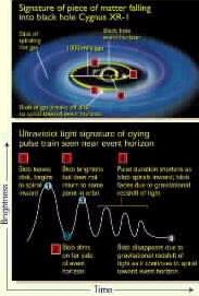
The Black Hole has always intrigued me. I have read allot of the literature on the subject wherever and whenever I can find it. It is still as mysterious as the first time I read about it when it was just a theory. I have my own thoughts about black holes that seem to coincide with my spin theory in magnets. I will reveal some of these thoughts with you, keeping in mind that none of it is proven factual. Only thoughts. Spin. Spin. Spin. Is it the huge amount of mass that causes the gravity which is so strong that nothing can escape its hole? Or is it spin that causes the gravity that we don’t see? From the material I have read, a star without any spin is actually rare (from what they believe). It is hard for me to comprehend a star being born without spin. Once a body of spin is started in a vacumm, it would seem to compound upon itself. As this spinning sun body dies, it shrinks in size therefore increasing spin. It is written that if the speed of spin mass exceeds what the mass can withstand as gravity, it will fly apart or explode. I can understand that. But what if gravity is a pure product of spin? In some cases it is. Such as a slow spin for a spacecraft to obtain artificial gravity. Let’s look deeper. If gravity was a product of spin, it would rarely ever fly apart. The smaller the star became, the faster the spin, and the stronger the gravity field. The stronger the gravity field, the faster the spin. No matter what the mass of the star is, the end is dismal. The spin becomes so strong that nothing escapes. Matter is squeezed into nothingness? Or is it? Something cannot become nothing in our universe. But what is the black hole not telling or showing us. Could there be a exit of our 3D universe at these black holes? Could the black hole have a neutral zone in which spin image is reversed at a Bloch wall of sorts at it’s center and expell the matter into another universal polarity or beginning? What about time? What would time even be like in the black hole, or would it matter? I can only imagine. We try to examine the black hole from our prospective and it makes no sense using our form of physics. The physics seem to conform to everything else. Why not the black hole? Should we change our prospective? Something is missing. Let’s think even deeper. To be continued…… Robert
– Byfilar Electron Sink :
Pulsing a byfilar coil can add more charged electrons to a system than was used to pulse the coil. Perhaps a strong statement, but allow me to prove my point. The byfilar coil is a unique arrangement. It can be wired in several different configurations, but I only wish to talk about two. Series and parallel. Lets suppose we have a coil made of (2) layered windings at 20 ohms of resistance each. Wire these (2) layers together in series by connecting the end wire of the first layer to the beginning wire of the second layer. (See drawing) This doubles our resistance to 40 ohms. If we apply a voltage and current to one end of the wire, a small cumulative effect occurs known as the E-field. This current in simple terms is working magnetically with each other flowing in the (2) windings. There is no cancelation between the two, only a additive effect. If we pulse the voltage and current towards the limit of the wire resistance of 40 ohms and abrubtly disconnect power and switch the (2) coil windings to a parallel connection. What happens? If we also provide a large cap in line with this coil in the collapsed state, we have created a large electron sink. The windings are now instantly at 20 ohms of resistance (each) in the collapsed state. BEMF literally floods into the parallel coil windings with a vicious cooling effect. The same amount of wire, but one half of the resistance. This electron avalanche effect will overshoot and also fill the capacitor easily in this collapsed state. Then we are ready to switch back to series and start the process all over again with a increased additional supply of charged electrons in the capacitor. We can use these newly charged electrons in anyway we wish. One can accumulate and dump them back to the supply battery or send them elsewhere to supply another load of sorts.
Click to see drawing. http://www.callowayengines.com/electron%20sink.jpg
– Calloway Gravity Engine :
Final drawing. Use a 32 inch drum or larger. Once this design starts rotating (give it a little push) #4 rolls backwards, #1 moves off TDC or 12 o’clock, #7 rolls right to the center. Then it will quickly gain a speed up to the (weight set) rpm. The wheel spin gets to a point of “out running” the weights, so a smooth regulated rpm is achieved. Expect no more than 50 to 60 RPM. Do you wish to go green with engine power? I do not consider this as ‘perpetual motion’. This engine is powered by the force of gravity. We will not use up this clean energy source. Gravity is always here. This is as green as it gets. I do not expect you to believe these statements because you have been taught differently. I assure you that what I say is true. Simply build it to see the results. Robert H. Calloway
Click here to see drawing. http://www.callowayengines.com/call1.jpg
– Perpetual Motion :
One might ask: Why experiment with a gravity wheel? It would be considered perpetual motion which is indeed impossible? Could magnet designs be a better prospect? Magnets have (2) forces, attract and repel. Would gravity be considered to have (2) forces? Of course!! Gravity has a force on mass that pulls downward and that same force resists the mass being lifted upward. So one could say, gravity and magnets have simular force properties. The magnets force act on iron, while gravity forces act on any type of mass, including the magnet itself!! Would it not be easier to experiment with just gravity forces? Of course we do both here, but gravity is better defined and easier to work with for experimental purposes in my opinion. It is important that one watches the center of gravity in a wheel closely. I can easily spot flaws in other designs by using this method. Most try to make the wheel do something that it does not want to do. You can only do that with a outside power source. You must work with the wheel and encourage what move it wishes to make next. Everyone seems to miss that point. I do not criticize anyone for trying to build a gravity wheel, but they must abide by this one rule: The center of gravity must constantly change in the wheel(s) favor for it to do work using attraction of any kind. This means a constant unbalance must be sustained at the center of any wheel naturally. Most try to get the unbalance from outside in using a more aggressive manner. Working with nature is easier than working against it. Why paddle up stream when it is much easier to drift with the current?
– Magnetic Gate :
It seems glaringly impossible to build a working magnetic gate. We have always been told or taught that one simply cannot do so. Through the last several hundred years, many a soul has went to their grave trying to do so. In the end, physics simply told everyone that it was a impossible feat. People listened. It was then taught in our classrooms of universities with vengeance. The laws of physics forbade anyone that even pursued the silly notion that a engine could be built, using nothing more that magnets or gravity for its own operation. It was considered perpetual motion. It always fascinated me that something had to be the driving force in a magnet. The question was, could one harness this force? I tackled this question aggressively. It became my livelihood. I built many failures through the years. Over the last twenty years of constant pursuit, I learned it was possible. I learned that the magnetic gate is the holy grail to a successful magnet engine. I now understand how it evaded everyone. I could not believe how much internal mind set was inside me and everyone else that has ever experimented with magnet engines. Studying the inside of a magnet revealed its secret to me. It was simply attraction. Forget repulsion for it was not needed for a magnetic gate.
– The Holy Grail :
The holy grail is ATTRACTION. Yes…..attraction and only pure attraction. Two designs that I am very familiar with are the Bowman motor and the Perendev designs. Both could work using attraction with angles. The Perendev design could work with the following measurements. The rotor magnets must be spaced at 1/2 the diameter of the rotor magnets diameter used. The same size magnet must be used in the stator. The magnets in the stator can be spaced at the same measurement. Spacing should be increased, but not necessary. I have used 25 degree angles from tangent in both the rotor and stator. 18 degrees could also work. I recommend using nothing smaller than 7/8 inch diameter magnets. The length of the magnet is critical. Of course it may still work with using smaller magnets. Shields around the rotor magnets could be used to keep from stressing the magnet fields while being so close together. But should not be necessary to run. No shields are needed in the stator. But they could be used to keep down stress. Let me warn everyone NOW that this design would be a beast. It would be a very powerful engine. With complete wrapping of the rotor with full stator magnets would be dangerous. It would run away. The torque could be huge. Build at your own risk. If controlled, it should run under load until the shaft bearings fail.
– Pulse Coils :
There are pulse motors listed at many websites. I feel that anyone interested, will know how the basic operation of these designs work and know how to build one. I have decided that there is no use in describing the build of a pulse motor. They are all about the same. However one needs to know how to build and correctly wire pulse coils to be successful. This is indeed the heart of a successful build if you wish for a good return with additional potential gain. (see drawing below) There have been many descriptions of different coil builds. Some of them are claimed to be using exotic types of core material and seemly mysterious windings. Its just not that complicated. First, lets look at a small 10 foot in length piece of #19 size wire. This small length of wire holds the potential for voltage and current. The electrons that is in the wire are ready to be used. We simply must compress it. The same can be seen in a garden hose that we have filled full of water. The water is there ready to be compressed by applying pressure to one end of the hose. We apply pressure to the wire by connecting it to a voltage and current. We don’t have to fill the wire with anything like we did with the garden hose. The electrons are always there in a relaxed postion. Let’s say we apply a 100 DC volts to this wire slowly with the other end grounded. What happens? It will burn the wire up if enough current is used. What if we apply this 100 volts very fast in DC pulses? What about the time in between pulses? Anytime a coil is pulsed it applies pressure to the electrons already in the wire. This pushes out the electrons at the end of the wire FIRST to the load.(rather slowly I might add) If the pulse is strong and quick enough, electrons burst unseen from the wire at all sides. A kind of radiant energy of sorts. It will tingle your skin. When the coil is relaxed (in between pulses) any electrons lost rush back into the coil from the environment or vaccum. The coil will be replenished when it is in a relaxed state for any loss of electrons that it needs to orbit the atoms of the copper wire in the coil. Now, if we pulse the potential into the coil fast enough, a interesting event happens. In the relaxed state between a pulse, the coil is at a net loss of electrons momentarily. If we switch the coil to a capacitor at this time, this causes a “extended avalanche effect” to occur from the environment or vacuum into the coil, that spills over into the capacitor. This momentary avalanche time has been extended by using the capacitor. This rush to fill the coil void of electrons from the vacuum also causes a significant voltage rise. By looking at your wire tables and knowing the resistance of your wire at your chosen length with your voltage used, you can build a fine coil(s) to run a pulse motor and have it return plenty of potential. You must push the current in the wire of the coil towards the high end limit. But the faster you pulse the coil, this limit drops and performance increases. Heat is made in the coil from being pulsed, but cold electrons entering from the vacuum cool the coil instantly. One should have a cool or cold coil(s) to be operating efficiently. A cold coil simply means that a over abundance of vacuum electrons are being re-supplied to the coil and cap system while running than is actually being used. The capacitor acts as a extension of the partially drained coil of electrons, and the vacuum must re-supply the copper wire with a balance of electrons for the atoms in the wire. In doing so, the cap has been supplied with electrons also. We have simply tricked the vacuum into resupplying the coil and the capacitor . A soft iron core is all that is needed. Another trick imployed, is to wind a coil byfilar. Use the extra winding to dump potential from it into a cap. You can even wind the coil tri-filar and use the 3rd winding for a trigger to pulse the coil. One can then switch all of these coils to series connected (as a driver) in the relaxed state to increase potential. You can wire a extra coil in a series byfilar method and collect some of the E-field and radiant effects.
This directs potential in the same direction as the pulse relaxation point. It seems that some magical event is happening in these coils by some folks. It is not. It is a natural event that happens if you wire your coils properly and switch them into a cap in the relaxed mode.
Click here to see a simple circuit. http://www.callowayengines.com/simple%20circuit.jpg
–Magnets :
When one holds a small magnet in hand, you have a enormous supply of locked magnetic electron vortex spin energy. The exact center on the face of a magnet is where the maximum flux strength is found. The vortex center. The vortex center strength fades as it moves down towards the Bloch wall. Electron spin is the very basic foundation of power that drives the universe. Electron spin rotation is everywhere. Locked magnetic electron vortex spin can power all of our energy requirements forever. Basic formation of a magnet is wrapping iron with wire down the length of the iron. When electrons as current is passed though the wire a magnetic field occurs. This lines up domains in the iron to cause a north and south pole mirrored electron spin image on each end of the now made magnet. The spin direction of the electron current through the wire is the same, up and down the whole length of the iron. When the electron current is removed, a unseen frozen mirrored image of the electron spin has remained imprinted in the domains of the iron from the wire causing a static magnetic field in vortex fashion to occur. This is called locked electron spin in a magnet. It is now a identical three dimensional memory image of electron spin from the wire. Nothing is actually moving in the magnet domains. It could be considered a 3D photograph of what was. The memory of electron spin is preserved deep in the domains of the magnet. Also deep inside the magnet at the Bloch wall, something different has occurred as we look at it in three dimensions. Imagine standing deep at the center of the Bloch wall and looking towards the north pole. We see a clockwise spin rotation. Now turn around and look at the south pole. We now see a counterclockwise rotation. But the rotation looking from the outside is all in the same direction. A paradox of sorts. This is why the Bloch wall is demanded in a magnet. It is a boundary for the beginning and the end of opposite locked vortex spin rotations in three dimensions from within. (three dimensions require a beginning and a end) If one observes this from four or higher dimensions, the boundary or Bloch wall is not needed as we would simply have a magnet with the same like pole on either end. The locked vortex spin becomes infinitely weak and will eventually ghost at the Bloch wall, thus this boundary occurs for opposite vortex spin directions. A black hole (which is a vortex) should have the same characteristics. One spin direction in, the neutral zone, and then a opposite spin direction out into a new universe or beginning. This static image of spin from the magnet can now be passed on to another iron partner using what is called the magnetic flux field. This causes it to mirror the spin image and become attracted to the magnet. In all actuality, the magnetic flux field would be better named as the ‘static spin image flux field’. Vortex activity can be learned from watching current in a fast moving river of water. Water vortexes of the same spin rotation attract, while opposite rotations repel each other. This occurs with any kind of spin. The weather as in lows and highs. The high is a clockwise spin and the low a counterclockwise spin. Tornadoes, hurricanes. Their beginning is from electron spin. This is the driving force of the universe and beyond. Spin rotation will also be found in the understanding of gravity. Deep study of magnets and how they work will reveal amazing finds in science about how our universe does indeed operate.
Click here to see magnet pic http://www.callowayengines.com/att20.jpg
– Calloway *V* Track Engine :
Below, you will find a drawing of a possible *V* Track rotary design by Ross. I have not built this concept as of yet, but you are certainly welcome to give it a try. It would seem to me that using (4) cylinder magnets in a rotor configuration inside a *V* track stator would greatly enhance the chance of a successful engine. The weight differential between turning the rotor group verses turning the stator group is obvious. I would advise keeping the *V* track itself stationary. Another reason is, we can use (4) magnets or more in the rotor group to help us escape the *V* track. One needs to understand what needs to happen at the gate for a good escape as I have shown on the *V* Track Video. http://www.fdp.nu/shared/manager.asp?d=filesCalloways%20Perendev You don’t want a sticky spot gate. You must have a dead spot gate. There is a great difference between the two. Making a dead spot means no attraction or repel *INTO* the gate area. You glide right through this specifically made area. It is like cruising down a road and turning off the engine power for one second, then start the engine power back up. It is hardly even noticed. It is a balance of magnetic flux between the end and the beginning of the track. With (4) cylinder magnets in the rotor, one magnet would still be pulling in the track while the other magnet at 90 degress is escaping the track. They should compliment each other. Perhaps, more than four magnets in the rotor would enhance the design even further. Only experimentation will show what works the best.
Click here to see drawing. http://www.callowayengines.com/vtrack.jpg
## Permanent Magnet Motor (Non_Electric) by Robert H. Calloway ; from http://www.keelynet.com/energy/callomag.htm
Hello All, It is time for this to be released. Build it for yourself and see the results.
Permanent Magnet Motor (Non_Electric) – 04/14/01 ; Updates are appended as of 07/11/01
courtesy of Robert H. Calloway, billc9@prysm.net via Henry Curtis, hcurtis@mindspring.com
I have been appalled by the always present negativity that a PMM cant, and will not work. It is said that the (2) forces, north @ south will always equal, no matter what you do. Other fairy tales are that the magnets would heat up if they were doing work.
I am here to tell you that this is a bunch of cock and bull. Dont believe these statements. This report is written to inform you that it can be done. Maybe after reading this you will reconsider on how to build a PPM.
First, do some research. Please see: http://www.keelynet.com/gravity/curtis.htm ; Read this whole article, read everything associated with it, plus the patents.
For a look at a PPM that I built and dared anyone to build, Please see it at the energy21 website titled: Hamster Cage Motor (the entire file is appended after this article). The Hamster cage motor is not considered by me a usable design, but it proves that it can be done.
For a PPM that will do some work, we must consider the ideas of the Minato PPM. For a legitimate PPM, no electric coils or power must be considered. In the latter statements of the above url, he refers to using a coil or coils. Forget that. Build the motor to run on nothing but permanent magnets.
Purchase a 36″ wheel. Set this wheel up on bearings to freewheel easily. Purchase 50 Radio Shack part# 640_1877 magnets. They come 10 magnets to a bag, so 5 bags will do. Glue these magnets on the outside face side of the wheel, in a fashion shown on the url.
The correct placement of these magnets will be when the wheel gates by a 5″ long, by 2 1/2″ wide, by 1/2″ thick vertically curved magnet in the repulsive mode. The magnets will cover no more than 180 degrees of the wheel.
When gluing magnets to the wheel, start at the outside of the face of the wheel and gradually work the magnets inwards so that the latter magnets in the 180 degrees wind up 3″ inward outside of the wheel on the opposite side.
FACT.. if you have done this properly the wheel will gate against the large magnet for 180 degrees. The magnets that you placed gradually in to 3″ will not impair the wheel when it comes around to get back into the gate. The wheel will quickly build a speed of about 1200 RPM. My wheel is 1″ plexiglas which is heavy. A lighter wheel will be faster. The wheel also needs to be balanced after proper placement of the magnets.
Never consider a smaller wheel. Why? A smaller wheel with magnets attached causes closed flux loops with the main or primary magnet.
When testing your wheel after the magnets are glued on, the wheel must gate freely through all magnets for 180 degrees then coast back around and back into the gate which starts the whole process over again. I like my motors ccw, but one can place the magnets to run either way. One can then gang rotors on a common shaft to produce power.
With this much said, one should start by gluing the magnets all the way around the wheel 180 degrees without trying to work them inside 3″. You will need practice on getting a perfect gate for the 180 degrees. A jig wont do after 6 magnets are placed. You will encounter lockups and slow downs until all the magnets are placed correctly on the wheel. It takes much patience.
With the magnets placed around the wheel along the outside, you will be able to gate out, but not be able to get back in. You can experiment with the gate by moving the large magnet out when the wheel comes back around to get in the gate. The wheel will keep turning and speed up quickly using this test method. When the wheel is setup correctly with the magnets moved in 3″, the magnet can be placed in a permanet position by the wheel in a hands off situation.
The wheel gates because of the relative size and angle of the wheel magnets versus the large size of the primary magnet. I suggest using “Quick Grab” glue wich is sold at Walgreens drug stores. It is a slow drying glue, but has a good instant bond in which a magnets position can be tested quickly. The magnet will pull off easily if in the wrong position, unless left overnight.
Keep in mind that a magnet placed wrong early in the process can effect the gate later down the line on the wheel.
NOTE! – CRITICAL TO ADJUSTING A MAGNETIC PMM – I have used metal filings in a plexiglass rectangled box just to view the various flux field effects as I placed magnets on the wheel.
This PMM has a strong rotational push and a very strong kick leaving the 180 degrees of magnets. When ganging (2) rotors on one shaft, the rotors distance between them must be at least 30″. The primary or main magnets must be placed on opposite sides of each rotor. But then..it is said that it cant be done… I have given you enough information to get busy.
Regards,Robert H. Calloway
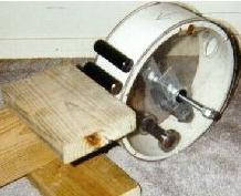
# THE HAMSTER CAGE MAGNETIC MOTOR
Ok the design works on the principle of a hamster cage effect. Have you ever seen a hamster exercise in the wheel in his cage? As he tries to run up the wheel he goes nowhere, but the wheel goes around and around.
If you take 2 rather large cylinder magnets and turn them so they oppose each other, one will roll away from the other. You can actually make the magnet go uphill with the other magnet without touching the second one.
Keep in mind that the magnet is not trying to turn to escape the other magnet, it is only getting away from the other magnet by rotating because it is round. Can we use this energy of the magnet rolling away from the other as work? I did it twice.
The rpm on mine was slow maybe 50 rpm. It turned about 16 turns before the top magnet hung up on the side plate. I have not been able to get it to work that long since. The design is quite simple, but much patience is needed in the building and adjustment of the magnets for the motor to work properly.
As I said, adjustment of the magnets must be precise. Maybe one of you Engineers out there can perfect this design.
– This motor consists of (4) 1×3 and 3/8 inch Alnico cylinder magnets. Also (2) 1″id x 2″od stainless steel bearings.
– The cage is made of schedule 40, 10″ id PVC pipe cut to 3 and 1/2 inches wide. The side plates are 1/8 inch plexiglass cut in a circle 11″ across. The shaft is all thread 7/16 cut at a length of 10 inches.
– The bearings for the shaft and plates are 1/2 id x 1 and 1/16 od inches, standard bearings.
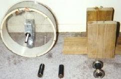
A cradle must be made to hold (1) “chaser” magnet inside the wheel. This cradle must be attached to the shaft to oppose the “running” magnet.
The reason for such large magnets are that each one has enough weight to keep from “flipping” when they are in the opposed position. Plus the weight to wheel ratio on the motor is a serious consideration.
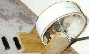
When the “chaser” magnet is in position in its cradle from the shaft, the “running” magnet is opposed. It tries to go up the wheel away from the “chaser” magnet.
But this does not make the wheel turn, in fact the force on the “running” magnet is held against the wheel. It cannot turn. We have to back off of the “chaser” magnet to give the bearings on the “running” magnet a chance to roll backwards, but the force of the “chaser” magnet is there, but not as strong.
When we put the same application on top of the wheel on the outside of it, we offset the balance of the magnets repulsion causing the wheel to turn, because the weight of the magnet offsets the centre “running” magnets repulsion from the “chaser” magnet.
The top “running” magnet starts to roll backwards causing the centre “running” magnet to roll forward causing the wheel to turn.
Be warned…the wheel must be in perfect balance, plus all these adjustments are critical. It is not as easy as it seems! It takes much patience to get the adjustments correct to start the wheel turning.
The plates will extend beyond the edge of the pipe, this is what it must do. We are building a hamster cage for the magnets. Mount bearings in the centre of each plate and attach them to each side of the pvc pipe using brass screws. I used all thread material for the shaft.
Let me say here that it is of the most importance that the wheel be in perfect balance. I used pennies taped to the side of the wheel to obtain this.
Now, build a bracket to hold one of the magnets inside the wheel attached to the shaft. I call this the “chaser” magnet. The chaser magnet must not contact the wheel anywhere. Make your shaft a little long so as to adjust the chaser magnet from outside the wheel. I built mine out of aluminium carpet strips. It also helps to cut a 2″ hole in each plate to access the magnets.
When the wheel it built, build a stand to hold the wheel supported by the shaft on each side. Purchase (2) stainless steel bearings1″ id by 2″ od. Place one on each end of the “running” magnet. Be careful of your choice of bearings, some stainless steel bearings are attracted to magnets depending on the material they are made of. I suppose brass bearings would work if they can be found.
Place this “running” magnet inside the wheel through the 2″ access holes in the plates in front of the chaser magnet. If you have your chaser magnet and bracket built right, you should be able to move the running magnet back and forth by turning the shaft by hand outside the wheel.
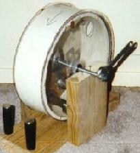
Now, back the chaser magnet up away from the running magnet until the wheel starts to move in the opposite direction. Keep it in this position for now. Take the other 2 magnets and place them on top of the wheel opposing one another. Note: these are a chasing and running magnets also.
Using the chasing magnet towards the bottom of the wheel gradually come down the side of the wheel holding the running magnet suspended against the wheel. This is why the plate sides overhang the wheel to keep the magnets in line and to stay on the wheel.
Note: these magnets do not have bearings on them. I did wrap the running magnet with one turn of electrical tape to give it “traction” so to speak against the wheel.
When the wheel starts to turn, stop and build a adjustable bracket to hold the chaser magnet in this position. This is, as should be a “hands off” motor. Build brackets and a adjustable stop for the shaft also.
Go back to the shaft and bring down the chaser magnet slowly and the wheel will turn if the adjustments are made correctly. Adjustment of the bracket holding the magnet inside the wheel should be made adjustable.
All these adjustments are critical and takes much patience to do. But if you get them right, you will be humbled to watch it work.
# Improvements:
I think if tracks could be made in the wheel hub, inside and out, that the magnets would stay in line more. Perhaps the wheel could be made of a better material, such as aluminium. The magnets still have a tendency to “cock” without tracking.
Balance could be much better with a aluminium wheel. The distance between the shaft and the cradle to the wheel is critical. The “chaser” magnet seems to have more down force on the “running” magnet as well as a repulsive force up the wheel.But the repulsive force seems not as critical. I wish someone would consider replicating this design.
If this motor has a previous patent, I’m not aware of it. I give the design away as shareware. Use it as you wish, but remember who offered this design! Send all huge donations to me personally.
Contact the Inventor Robert H. Calloway billc9@prysm.net
# Update 07/11/01 – (still verifying this)
The following email was received by Robert Calloway and Henry Curtis, then forwarded to KeelyNet, we have asked for more details on the magnets, placement, RPM and possibly photos which will be appended as received.
Hey guys, this is incredible.
I was working on a design for a Perpetual Motion Device (PPM) based on magnets and I came across your site. My design was altogether different from yours, but I was searching on magnets and found your site. Well, since I had a workshop FULL of magnets, I decided to try and build a Permanent Magnet Motor for myself. I thought it would be difficult to get the magnets aligned correctly, but it was quite simple in fact. I spent about 30 minutes tops arranging the magnets.
My design called for two thin sheets of Plexiglas cut into 36 inch circles. I mounted bearings to each, and mounted them on an axle. I took two curved sheets of Velcro, and attached them to half of each wheel. I glued the other side of the Velcro to the sides of each magnet. This would allow for easy repositioning of the magnets. I then sandwiched the magnets between the sheets of Plexiglas, to add to the Velcro’s strength in holding them in place.
I weighed the magnets, and added weights of equal weight to the other side of the wheel, to balance it. After a few lockups and magnet repositioning, it did start to spin and spin strongly! It’s pretty impressive.
Anyway, I then bought a simple 6-volt light generator for a bike at Wal-Mart and started to power all sorts of things. I want to find a small 12-volt generator, so I can power practical 12-volt items which are widely available. I’m hoping, quite soon, to be able to power most electrical items in my house from generators running off these things.
This invention is HUGE! How come you guys are not more popular?
John
# Update from Robert Calloway on 07/11/01 :
Magnets…leave the thought of north and south behind for now. Think flux, repelling flux against another repelling magnet. Flux can be manipulated. Flux is the wind. The flux fields between two repelling magnets does no join or intermingle. They bulge and deform into different shapes and patterns. Building a PPM requires looking at these flux patterns. All magnets are never the same, even though they look and feel the same.
One could build a PPM and then copy it exactly, and it would not work. You MUST see the flux pattern.
I have specifically said you must view these patterns using a box with metal filings. If you build a PPM without doing this, you are very lucky. “John T” has said that he has built the PPM, and I hope that he has done so. He has also said that he has turned a 6 volt generator with it, and I hope that he has done so.
“John T” must explain how he turned the generator with the bearings installed to the disks? That means there is no shaft to turn to drive the generator. He could conceivably turn the generator from the disks I suppose. I truly hope he did.I am beholding to an agreement against full disclosure on this design.
Regards, Robert H. Calloway
# See also Magnetic Anomalies at Keelynet.com: http://www.keelynet.com/ohsako/ohsako.htm