WARNING THIS KIND OF HIGH VOLTAGE GENERATORS ARE VERY DANGEROUS
(page created November 2007)
See also Ed. Gray pages about Sparking Converters https://tesla3.com/tesla-par-edwin-gray/, and the page Spark Gaps https://tesla3.com/spark-gaps/
Marx Generator 1
http://www.vk2zay.net/article.php/13
The Marx Generator is a simple way to generate lots of voltage. It isn’t a new idea, charge up a stack of capacitors in parallel, discharge them in series. When you use high voltage capacitors and spark gap commutators the resulting sparks are quite impressive.
If cheap loud and long sparks are your aim, a Marx generator delivers them with excellent simplicity. Just a slack handful of bits and pieces (although somewhat exotic devices are required) will build you a respectable noise and light show that can be powered nicely with a flyback or similar source of kilovoltage DC.
If you are going for maximum spark length and pushing the corona and breakdown limits then Marx generators are not the best, they are pulse mode (sparks) not continuous arc/flame markers. A tesla coil would be a better project.
Marx generators make excellent lightning simulators. They are also very hostile to surrounding equipment, as my power supply well knows. My first simple proof of concept device fried my bench PSU after a few shots. Be careful they can bite you very hard too! I carefully discharge each stage before handling it, but now and then I’ve missed a cap and got bitten, it hurts.
Unlike Cockcroft-Walton multipliers, the Marx Generator needs no diodes, and only uses one cap per stage. This reduces their cost enormously, at the expense of the mechanical complexity of the spark gaps. Give one a go, you’ll love ’em!
Prototypes:
– 2003-02-09: Quickie Marx Generator http://www.vk2zay.net/article.php/60 Built to show ceramic caps are generally OK for Marx service.
– 2003-01-28: Knowing Your Coronatron http://www.vk2zay.net/article.php/59 Characterizing the testing supply, and some more thoughts towards building “the big one” some day.
– 2003-01-27: A Bigger Marx Generator http://www.vk2zay.net/article.php/58 More new capacitors lead to a multi-Joule device.
– 2003-01-14: Choke Charging Experiments http://www.vk2zay.net/article.php/57 An attempt at a choke charging Marx generator.
– 2003-01-05: More Marx Generators http://www.vk2zay.net/article.php/56 Two new prototypes for the New Year.
– 2002-12-14: New Capacitors! http://www.vk2zay.net/article.php/55 Some eBay wins pay off and my first serious Marx Generator is born.
– 2002-12-08: Second Try http://www.vk2zay.net/article.php/54 The Proof-of-Concept unit gets an extension.
– 2002-11-03: First Proof-of-Concept Unit http://www.vk2zay.net/article.php/53 The first Marx Generator I built.
More Marx Generators
http://www.vk2zay.net/article.php/56
Two new prototypes for the New Year! With new capacitors and different construction techniques.

The first is made with doorknob capacitors I found laying around in a box. 470p, 30kV capacitors designed for pulse discharge and RF service. Note how one discharge has followed the desk surface, interesting. The charging resistors are two series connected 10M 1W units, on each side of each stage. This once again was a bad choice. Corona has come back to haunt me:

As these capacitors are good for 30kV I tried to space everything such that I could get the full voltage performance if I wanted to. These 1W resistors just aren’t up to it. The have small, but very sharp points on the end-cap to resistance film soldering, the molding compound doesn’t cover these well and they punch through in moments. The solder tags also suck, never use them in HV work! I should have known better, they are too thin and spray off the edges. They are also quite painful to work with mechanically. The end result is losses and more than occasional misfires when running at only 17.4kV:
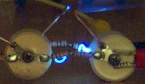
The blury blue thing near the first gap is the soda straw I used to trigger it. As in my previous discovery, I can fire the gap manually by approaching it carefully with a dielectric. This proved quite handy for making these pictures, you’ll see it in all the ones I took this evening. I simply set the gaps to (just) not automatically fire, turn off the lights, trigger the camera shutter and start waving the straw near the first gap.
With an erected capacitance of only 117pF and charged a mear to 17.4kV the report is deafening. There is over 280mJ of energy stored in these caps at that voltage. This device is moderately dangerous. I haven’t been shocked by it yet, and I don’t want to be, it could be very nasty if it got you good.
As with my last device, if a striking ground is not offered, or is too far away, pale purple sparks jump all the gaps with a very soft cracking sound. The higher voltages involved in this unit though offer no doubt erection is happening properly. The hairs on my arm stand on end from the huge electric field generated at the top. Invisible streamers nip your fingers gently, if you are the closest object to the output terminal. It isn’t painful, more surprising, but a few tens of millimeters closer and it might be a very different story.
With some corona dope I may be able to rescue this device, otherwise I’ll have to junk the resistors (and the rest of the 500 on the tape, damn!) and use the 1/2W devices that were so much better in the previous unit. Still, it works as-is, with 60mm long, very loud and fat, sparks.
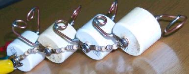
The next unit is made with eBay win capacitors. 2n2 10kV Russian military surplus capacitors. I am still waiting on a few other capacitor types to arrive, but most are of the same make as these devices, just different voltage and capacitance ratings.
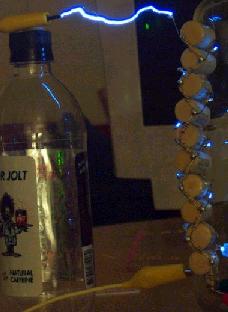
That little leader branching out and back into the main spark is rather interesting, I thought.

I am not proud of the construction, I tried very hard to keep it all neat and tidy. Then I hung it up to test it, and it all went wonky. The gaps alternate each side of the stack, which was necessary because of the lead length, unless I wanted to make a lot of gaps out of extra wire. I think next time I will make the effort, their leads are quite thin, about 0.71mm and make barely sufficient gaps.
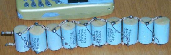
This is probably the best Marx Generator I’ve built so far. While it has a slight leakage problem (I can hear some, but not find it), and the gap staggering makes it a little more tempremental to tune, it delivers deafening sparks over 100mm long with ease. It has an erected capacitance of 220p, charged to 7.4 kV from the -ve rail of the coronatron PSU, it has a stored energy of about 600mJ. I could raise that to 1.1J if I could find the extra 2.6kV safely. I am cautious about over-stressing these caps, they don’t really look like they were built for pulse service. I have not done a destructive test either, I purchased only 20 of them and they are a little too pricy to just blow up.
Thoughts for the Next Round : I really need to get some corona dope and seal all the charging network. I’ll fall back to 1/2W resistors, they are better at the HV, and are fine dissipation wise. I’ve worked out how to test the charging network components under the sharp rise time transients they’ll experience:
The principle of operation is simple enough, the first cap is charged through the 10M resistor, the second through the device under test. The spark gap breaks down, pulling one end of the device under test to ground very fast. The entire stored energy in the first cap flows through the device under test as fast as it allows.
I’ve been considering moving to choke charging networks. The actual inductance required isn’t that big. The rise time of the discharge is fantastically fast, so even a few turns of wire would be a much larger impedance than the spark gaps.
I also have to implement an electrical trigger system. It is becoming a safety issue, as well as a performance one. One thing I did consider was using a small Marx generator to trigger a larger one. Perhaps triggering all gaps at once with equal length phasing lines to each gap. That should supply the ultimate in rise-time and jitter performance if properly implemented. I’d need some serious test gear to optimize that, but I can’t really afford it right now.
Jochen’s High Voltage Page
http://www.kronjaeger.com/hv/
Marx generator: The Marx generator is a voltage multiplier working on a completely different principle than all other multipliers http://www.kronjaeger.com/hv/hv/src/mul/index.html presented in here. Roughly, the principle is: charge a set of capacitors in parallel, discharge in series. One way to achieve this would be straight-forward via lots of switches. The Marx generator, however, is a clever way of doing this switching automatically, via spark gaps.
Schematic 4-stage Marx generator and actual realization, photographed in the moment of discharge.
The above figure shows the circuit diagram of a Marx generator. The values of the components are not critical, and therefore not given. Obviously, as long as the spark gaps are non-conducting, all the caps are charged in parallel from the 30kV source. Across each gap is the voltage to which the caps have been charged so far. Now they are adjusted in such way, that they fire and become conducting at just below 30kV. When this happens, the gaps act as a very low resistance compared to the charging resistors, so that the caps are suddenly all in series, and their added voltages appear at the output. Of course, even without load on the output, the caps will discharge more or less quickly through the resistors. That´s why the Marx generator is a pulse generator, producing short, but high voltage pulses.
If you look closely, the process of all the gaps becoming conducting at the same time is much more complicated. As the pulse is so short, all the gaps must fire at exactly the same moment – but this is automatically assured: as soon as G1 fires, G2 sees twice the charging voltage, making it fire quickly, and so on with the rest of the gaps. To ensure that this process starts from the very bottom, G1 is usually set slightly closer than the rest of the gaps.
Marx generators are mainly used to simulate the effect of lightning on technical high voltage components. Voltages above 1MV are easily reached. An advantage over cascades is that there is only one cap per stage (and no diodes at all, making it a rather robust device). However, there is one drawback: the maximum spark length is reduced with respect to DC, because a spark needs time to develop.
The simple 4-stage model shown in the photo was built with 2nF caps (homebrew, estimated to 30kV) and 2x 10MOhm resistors between stages. Charging is done with 30kV through a 200MOhm resistor to protect the DC source from any overvoltage kickbacks. The resulting 120kV pulse is enough to jump across a 10cm gap. Note that the same DC voltage (see Super-cascade ) is able to jump a gap twice as large.
Capacitors for a Marx generator must ne suitable for pulsed applications. Many cheap high voltage caps (MKT-types) are not suitable. Caps with PP or PE dielectric are good. The resistors can be a lot smaller than in my example, actually they might be substituted by chokes. A large charging resistor is recommended, however, as it protects the DC source and makes the generator controllable by slowing down the repetition rate.
© 2000-2006 Jochen Kronjaeger ; Last modified: 2004-12-30 16:17:36
## Project: 300kV marx generator http://www.kronjaeger.com/hv/hv/pro/marx/index.html
Construction and operation:
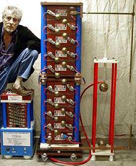
General setup The marx generator http://www.kronjaeger.com/hv/hv/src/marx/index.html in its current state has 10 stages, each consisting of
– one 8nF/30kV pulse discharge cap (commercial),
– one spark gap (in a first version these were just copper wires bent into a ring at the end to suppress corona, the current design is somewhat more sophisticated and uses spherical electrodes),
– two 2MOhm resistors (2x 1MOhm/5kV in series – commercial).
It produces a 300kV output pulse with a discharge energy of 36 Joule. The discharge path is more than 40cm long and produces a loud bang – enough to make it uncomfortable to the ears.
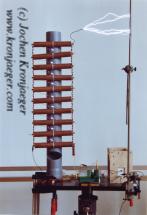
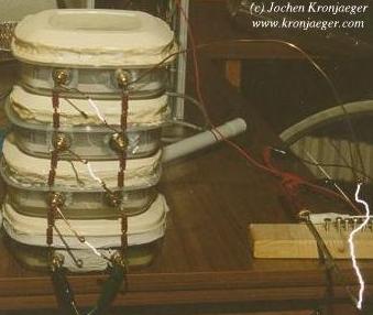
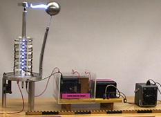
Time exposure of several discharges of the marx generator. The ladder-like construction is the actual generator, the caps are mounted horizontally on the grey PVC tube. Vertically, left and right from the caps, are the resistor chains. The gaps are simply bent wires. The vertical metal rod to the right is grounded. The remaining stuff is the charging system, a flyback driving a TV cascade.
Using a flyback driver with a subsequent TV multiplier and a 1MOhm charging resistor, the repetition rate is roughly once per second.
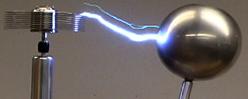
Spark gaps: In a first version, the spark gaps were made of about 1mm diameter copper wire, which was bent into a ring (about 2cm diameter) to prevent corona and premature breakdown. For optimal operation, all gaps should be equally wide. (Some say that the frist gap should be somewhat less wide, but for me it also works if they are all equal. Maybe this has some drawback that I have not yet noticed.). Adjustment is done by slightly bending the wires until a rod or tube of suitable diameter just fits through.
Schematic drawing of the marx generator with “wire gaps”.
While this construction was chosen as a quick fix and proved useful, disadvantages of this “wire gap” are obvious:
– The gaps are “wobbly”, i.e. sensitive to mechanical vibration, and easily get out out adjustment.
– Adjusting the gaps is a pain and rather time consuming, due to the elasticity of the copper wire.
The improved version makes use of 1cm diameter spherical nuts on M6 screws. The gaps are thus easily adjustable and should be stable at their position. The gaps are mounted into a cable duct with a lid which can be opened or closed, depending on whether you want the gaps visible or not.
Schematic drawing of the improved spark gap. For each stage, one such gap is mounted in the cable duct. The whole structure is then attached to the marx generator and wired to the caps.
Charging resistors: In the first version, the charging resistors consisted of a string of four 2kOhm 2Watt carbon film resistors each. This relatively low resistance of 8KOhm allowed for rapid charging and low voltage drop due to corona and other leakage currents, but also caused the output voltage pulse to decay with a time constant of around 30us. The achievable spark length was thus limited by the short duration of the pulse to around 30cm. Also, the resistors were operated far beyond their design voltage (probably 500V) and frequently broke down, in particular when the output was accidentally “open”, i.e. a spark did not develop and the whole energy stored had to be dissipated by the resistors.
The improved version uses two commercial high voltage resistors (Vishay HGR0939 http://www.vishay.com/docs/20133/hgr.pdf , 1MOhm, 5kV, bought via ebay) in series, resulting in much improved reliability and an increased falling edge time constant of 8ms. As a drawback, the charging time is also much longer and the “fire rate” lower, and corona losses are noticable now.

10-stage marx generator with improved spark gaps and 20MOhm charging resistors. The distance between the main discharge electrodes is 40cm. Taking into account that the actual peak voltage is probably less than 10x the charging voltage (30kV), this already comes close to the maximum spark length http://www.kronjaeger.com/hv/hv/msr/spk/index.html expected between needle electrodes.
Observations: The maximum discharge length depends on the value of the resistors connecting each stage. The larger this value, the longer the possible distance, up to some expected optimal value at least. Possible explanation: Once the gaps are in the conducting state, the caps begin to discharge through these resistors. At the same time, a spark starts to develop at the output terminal. This takes the longer the bigger the distance to ground is. If the caps discharge too quickly through the resistors, the spark has not enough time to fully develop. With the current values of R and C, the characteristic time is 8ms.
The discharge seems to induce huge voltage transients in ground and/or mains leads. This has resulted in a burnt mains switch and a destroyed ground fault interrupter. Grounding the marx generator seperately and decoupling the charging voltage ground with a resistor helps somewhat. This may turn out to be a major problem, as the marx generator naturally produces a huge voltage step with a risetime probably in the microsecond range, and the subsequent discharge produces a similarly steep current pulse which might be kA or more.
Marx Impulse Generators
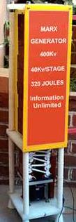
Updated 09/24/07 http://www.amazing1.com/marx_generators.htm
Information Unlimited, PO Box 716, Amherst, NH 03031-0716 USA
Marx Impulse Generators: Professional Equipment for Serious Research
Applications
– Generation of high power micro wave using virtual cathode oscillator devices
– Lightning testing on cables and insulators at 1.2/50 microsec and 8/20 microsec
– Material and dielectric testing
– Breaking of raw diamonds in mineralogy
– High voltage and magnetic pulser
– High repetition rate high power CO2 lasers
– Generating EMP on parallel plate transmission lines
– Bridge wire exploding
– Electron injection into nuclear reactors
– Electron accelerators
– Kilo amp linear accelerators
– Current injection and generation
– Radiation generator for high voltage steep pulser
– Flash x-ray generation
– Pulsed electron generation
– Short duration luminous flash for ultra high speed photography
– Firing boxes for pyrotechnic substance reliability testing
– Exploding unattended munitions
– Nuclear electromagnetic pulse generator
– Generation of plasma focusing
– Generation of axial plasma for injection purposes
– Remote de-programming of processors used in computers and other control circuitry
– Educational demonstration of electrical pyrotechnics, etc..
The Marx impulse generator can simulate a lightning strike. As an example most lightning discharges are in the order 1 to 100 kilo-amps with 500 kilo-amps a rarity. The electric charge associated is usually 5 to 50 Coulombs. At a voltage of 50 to 500 million volts this transforms to a considerable amount of discharged energy. The rise time of the discharge is usually 1 to 10 microseconds with a fall time of 20 to 50 microseconds. Even though this equates out to a destructive event the current rise is not as fast as the man made impulse generator. In other words Mother Nature got us in joules but not in nanoseconds!!! The reason for the relatively slow rise is due to the atmosphere not approaching an ideal spark gap switch.
The output of the Marx is under 100 kilo-amps but its current rise is faster than a natural lightning bolt. Materials testing such as cables transformers and power systems can be verified for integrity against lightning. Flash x-rays and the simulating of electro magnetic pulse (EMP) from nuclear detonations are possible using this device. The output can be coupled into a suitable load, parallel flat line antenna etc. For flash x-rays you must couple the output to a suitable x-ray tube.
How It Works : Marx generators are basically very simple in theory, a stack of capacitors is charged in a parallel configuration to a voltage “E” and then discharged in series with a voltage of “nE” where “n” in the number of capacitors charged. Sounds simple in theory but in reality several problems must be addressed. Selection of the capacitors will determine the peak current and rate of current rise during the discharge cycle that are now figures of merit for the system. Not only must we select the value of capacity and voltage but now must consider the discharge loop inductance and peak current handling of this part. Needless to say this part is far more expensive than normal oil filled filter capacitors. These capacitors once charged must be discharged in a series configuration through special precisely spaced spark gap switches for each capacitor. Open air tungsten or molybdenum electrodes with Bruce or Rogowski discharge surfaces now switch the required currents with low “jitter” Switching times are fast but can be improved in a nitrogen atmosphere or doping the electrodes with a radio-active isotope such as cesium 137 or nickel 63.
The initial charging of the capacitors is best done via a controlled current source. A good approach is the use of a current limited transformer operating at line frequency or a standard high voltage transformer with a current controlled reactor in series with the primary for higher power units. The use of semiconductors usually requires special circuit precautions and shielding from the EMP generated by most of the discharges.
The output of the transformer is rectified and voltage multiplied to the appropriate charging value and applied to the capacitors by high voltage resistors. Output is continuously variable with a variac. The system is triggered manually or by a +5 volt level that generates a high voltage pulse to a third trigger electrode of the bottom spark switch. This now commences where all spark switches now simultaneously fire dumping the total charge in nanoseconds.
Our basic Marx generators have charging resistors. Discharge resistors can be selected by the user dependent on the desired wave shape. Standard parallel plate transmission line with a gap of 300 mm or 500 mm is available to enable the user to couple the Marx for obtaining steep field strength of 100 Kv to 400 Kv per meter.
Available Systems From Our Labs : All systems allow charging voltage from zero to full value with manual and +5 volt fire control. Systems are complete and require 115 or 230 vac for operation. Discharge shaping resistors are available per your requirement or use as is for fast discharge.
Typical charging times/cycles is 4 to 7 events per minute with a rise time of 5 to 8ns and pulse duration of 50ns. System must not be in proximity to electronic equipment without suitable discharge shaping resistors.
Our Marx Impulse Generators are Available to Qualified Researchers on a Rental Basis with Option to Buy ; Contact Bob Iannini at: riannini@metro2000.net
IU1045 – 450KV @ 400 JOULES……………………. $1500.00/60 days
IU1080 – 800KV @ 3200 JOULES…………………..$3000.00/60 days
Price Examples:
– Model MINIMARX1 ; 20J ; 200KV ; 10 stages ; Caps Stage 10nf ; Rep Rate 10 pph ; Rise typ – Model IU1045 ; 400J ; 450KV ; 10 stages ; Caps Stage 40nf ; Rep Rate 20 pph ; Rise typ – Model IU20100 ; 10kJ ; 1.8MV ; 20 stages ; Caps Stage 100nf ; Rep Rate 3 pph ; Rise typ UM ; Dwell typ UM ; Ltotal UM ; Gap gas ; Ipk 14Ka ; Wpk 25.2Gw ; Size/Wgt 4m/1,900kg ; Erected CTance 5nf ; Price USD 98,540
We Will Buy Your Used or Surplus High Voltage Equipment ; We are constantly evaluating and purchasing used and surplus high voltage devices and components.
You may contact us by Email riannini@metro2000.net or Call: 1-603-673-6493 or Fax: 1-603-672-5406.
Off Shore Manufacturing http://www.amazing1.com/trio.htm
USP 7170198, Trigger arrangement for a Marx generator
Sack, Martin (Rheinstetten, DE, US), 01/30/2007,
at FreePatentsOnline http://www.freepatentsonline.com/7170198.html
In trigger/firing arrangement in a Marx generator comprising n stage capacitors–n being a natural number greater than 1-, the same amount of spark gaps and 2(n-1) charging branches, with the spark gaps operating in a self-breakdown mode, the trigger-/firing arrangement comprises at least a pulse transformer connected to an pulse generator in at least one of the charging branches of the Marx-generator, which with the associated stage capacitor bridges a spark gap–except for the output end spark gap–a pulse transformer is disposed, whose output winding operates during charging as a charging winding and whose input winding is connected to the pulse generator in such a way that the voltage pulse generated with this pulse transformer during triggering of the pulse generator is added to the charge voltage of the associated stage capacitor and, with a corresponding polarity, generates an over-voltage sufficient for initiating self-breakdown at this spark gap.
US Patent References
3229124 http://www.freepatentsonline.com/3229124.html , January 1966 Schonfield
3260865 http://www.freepatentsonline.com/3260865.html , July 1966, Jelenik-Fink et al.
3721886 http://www.freepatentsonline.com/3721886.html , March 1973, Phinney et al.
3746881 http://www.freepatentsonline.com/3746881.html , July 1973, Fitch et al.
3845322 http://www.freepatentsonline.com/3845322.html , October 1974, Aslin
4189650 http://www.freepatentsonline.com/4189650.html , February 1980, Aaland
4375594 http://www.freepatentsonline.com/4375594.html , March 1983, Ewanizk, Jr.
5153460 http://www.freepatentsonline.com/5153460.html , October 1992, Bovino et al.
Parent Case Data: This is a continuation-in-part application of international application PCT/EP2004/004101 filed Apr. 17, 2004 and claiming the priority of German application 103 20 435.3 filed May 8, 2003.
What is claimed is:
1. A trigger/firing arrangement in a Marx generator comprising n stage capacitors–n being a natural number greater than 1-, the same amount of switches/spark gaps, and 2(n-1) charging branches, with the spark gaps operating in a self-breakdown mode, the trigger-/firing arrangement comprising at least a pulse transformer connected to a pulse generator in at least one of the charging branches of the Marx-generator, which, with the associated stage capacitor, bridges a spark gap–except for the output end spark gap-, a pulse transformer connected, such that the output winding thereof operates during charging as, or also as, a charging winding/inductivity and the input winding thereof being connected to the pulse generator in such a way that the voltage pulse generated with this pulse transformer during ignition/triggering of the pulse generator is added to the charge voltage of the associated stage capacitor and, with a corresponding polarity, generates during the increase of the voltage pulse an over-voltage sufficient for initiating self-breakdown at this spark gap.
2. A trigger/firing arrangement according to claim 1, wherein the charging branches of the Marx generator have each only one charging winding and at least one of the charging windings is expanded to an pulse transformer.
3. A trigger/firing arrangement according to claim 1, wherein the charging branches of the Marx-generator each include a charging resistor and in at least one charging branch an pulse transformer is arranged directly in series with, or parallel to, the charging resistor.
4. A trigger/firing arrangement according to claim 2, wherein two charging branches which are each connected to a spark gap, include each an pulse transformer.
5. A trigger/firing arrangement according to claim 4, wherein the input winding of the two pulse transformers are arranged in series and connected to a common pulse generator.
6. A trigger/firing arrangement according to claim 4, wherein the input winding of the two pulse transformers are arranged in parallel and connected to a common pulse generator.
7. A trigger/firing arrangement according to claim 4, wherein the input windings of the two pulse transformers are each connected to an pulse generator.
8. A trigger/firing arrangement according to claim 5, wherein the pulse generator is connected electrically to a control device.
9. A trigger/firing arrangement according to claim 5, wherein the pulse generator is connected to a control device via a light conductor.
10. A trigger/firing arrangement according to claim 1, wherein the pulse generator and the input windings connected thereto represent an electric power supply and the electric power can be switched off rapidly by the power supply.
11. A trigger/firing arrangement according to claim 1 wherein the pulse generator is a voltage source and the output winding of the pulse transformer is provided with a throttle coil arranged in series.
12. A trigger/firing arrangement according to claim 11, wherein the voltage source is a capacitor with a switch or a, with regard to the Marx generator to be operated, small Marx-generator operating as a switch.
13. A trigger/firing arrangement according to claim 1, wherein the winding sense of the input side winding connected to the pulse transformer is such that the voltage induced in the input winding by the increase of the discharge current of the Marx generator is oriented opposite the voltage induced in the output winding.
BACKGROUND OF THE INVENTION
The invention relates to a trigger/firing arrangement of a Marx generator including n stage capacitors n being a natural-number greater than 1–the same amount of switches/spark gaps and 2(n-1) charging branches with the spark gaps operating in a self-breakdown mode.
With a uni-polar output voltage, the Marx generator has generally as many spark gaps as it has stage capacitors. In its most simple construction, the spark gaps operate in self-breakdown mode. To each spark gap, except for the output spark gap, two charging branches are connected, one to each of the two connectors of the spark gap. As a result, there are altogether 2(n-1) charging branches associated with an n-stage Marx generator. With a charging voltage U at each of the stage capacitors at the output of the Marx generator, a voltage pulse with a peak value of n*U is obtained at breakdown.
Marx generators which can be triggered in a controlled manner either have three-electrode spark gaps or spark gaps with a trigger pin similar to a spark plug, known also as Trigatron Principle. Such Marx generators are generally operated in single pulse mode. To trigger repetitively operated Marx generators spark gaps are attempted to be operated in accordance with the principles mentioned with regard to minimum wear (see [1]) or to make the triggering operationally secure by optimized trigger generators (see [2]).
Furthermore, laser triggering methods or the use of semi-conductor switches instead of spark gaps are being examined (see[4]). Another trigger method resides in the voltage inversion principle of the LC-Marx generator. In [5], a variant of this principle is described wherein transformers are used for the coupling between the steps. In addition, there are publications concerning the optimizing of the self-breakdown of spark gaps for the non-triggered operation (see [6]).
In spark gaps which can be triggered the trigger electrodes are subjected to high stress because of their exposed locations. Furthermore, the mechanical setup of a spark gap that can be triggered is more complicated than a spark gap without a trigger electrode.
It is the object of the present invention to trigger Marx generators with little wear by an over-voltage breakdown of one or more spark gaps at predetermined points in time particularly with regard to repetitive operations.
SUMMARY OF THE INVENTION
In trigger/firing arrangement in a Marx generator comprising n stage capacitors–n being a natural number greater than 1-, the same amount of spark gaps and 2(n-1) charging branches, with the spark gaps operating in a self-breakdown mode, the trigger-/firing arrangement comprises at least a pulse transformer connected to an pulse generator in at least one of the charging branches of the Marx-generator, which with the associated stage capacitor bridges a spark gap–except for the output end spark gap–a pulse transformer is disposed, whose output winding operates during charging as a charging winding and whose input winding is connected to the pulse generator in such a way that the voltage pulse generated with this pulse transformer during triggering of the pulse generator is added to the charge voltage of the associated stage capacitor and, with a corresponding polarity, generates an over-voltage sufficient for initiating self-breakdown at this spark gap.
The trigger/firing arrangement comprises basically a pulse transformer connected to a pulse generator. Such a pulse transformer is switched into at least one of the charging branches of the Marx generator which, together with the associated stage capacitor bridges a spark gap–except for the spark gap at the output side of the Marx generator. The output winding or secondary winding or the over-voltage side winding of the transformer acts during charging at least partly as a charging coil/inductivity. The input winding or primary winding of the pulse transformer is connected to the output of the pulse generator. Upon ignition/triggering of the pulse generator, in the output winding of the pulse transformer a voltage pulse is induced which is added to the charge voltage of the associated stage capacitor and, with the appropriate polarity resulting in an over voltage sufficient to initiate the breakdown.
Possible embodiments for triggering the spark gap/s are described, which, on one hand, cause reliable triggering of the Marx generator and, on the other hand, permit an efficient setup.
The Marx generator can be constructed in two ways depending on its intended use for repetitive operation or single shot operation. For repetitive operation, it has been found suitable to place a charging winding into the charging branches and complete at least one of these charging coils to the pulse transformer. In order to keep the electrical insulation expenses as low as possible or within limits at least at the ground-side charge branch such a charging coil which has been changed or expanded to an pulse transformer is placed.
If the Marx generator is charged by way of a charge resistor, at least into one charging branch an pulse transformer is switched. Its output winding is then arranged selectively directly in series with, or parallel to, the charge resistor.
In a Marx generator all spark gaps except for the output spark gap are bridged twice by a charging branch and an associated stage capacitor. At both connections of a spark gap always one charging branch is connected. The trigger/firing arrangement is such that an pulse transformer is installed in each of the two charging branches. Basically, this may be at each of the (n-1) spark gaps, again preferably at the spark gap with the lowest potential in order to limit the insulation expenses.
Preferably, the input windings of the two pulse transformers are connected electrically in series and are connected to a common pulse generator.
In a more complicated arrangement, each input winding is connected to its own pulse generator.
The pulse generator or generators can be differently controlled, either electrically or via an optical signal transmission. In the latter case, at least the pulse transformers all have the same isolation arrangement. If each pulse transformer has its own pulse generator then the construction components pulse transformer–pulse generator, are as far as isolation is concerned, equal at each stage.
The pulse generator and the input winding or windings connected thereto may be different in design. They may be in the form of a current source which can be rapidly switched off or it may be a voltage source. In the first case, the switch may be a switched transistor or switched transistors as they are used, for example, in the transistorized ignition system of a spark ignition engine. In the latter case, a choke coil (with core or core-less) is arranged in the charging branch in series with the output winding at the pulse transformer for limiting the current.
As voltage source, for example a capacitor with a switch or, for large power output, a Marx generator which is small in comparison to the Marx generator to be operated may be used.
To increase the reliability, the winding direction of the input winding for the pulse transformer is such that the voltage induced in the input winding as a result of the increase of the discharge current of the Marx generator is oriented opposite to the voltage induced by the output winding in accordance with the principle of the transformer.
The advantages of the arrangement described in comparison with a conventional trigger method reside on one hand, in a simple inexpensive design and, on the other hand, in a substantially lower wear than in conventional three-electrode spark gaps. As a result, a Marx generator for an industrial application may be built which has a long-term constant operating behavior. For a reliable operation in industrial applications this is absolutely necessary.
The trigger arrangement for a multi-stage Marx generator with at least one self-triggered spark gap will be described in greater detail below on the basis of the accompanying drawings.
BRIEF DESCRIPTION OF THE DRAWINGS
FIG. 1 shows a Marx generator with over-voltage triggering of the first spark gap;
FIG. 2 shows over-voltage triggering with transformers in both charging branches;
FIG. 3 shows the power supply of the trigger circuit from the charge current; and
FIG. 4 an exemplary plot of the induced over-voltage (100 ns/Div. 2.5 kV/Div.).
DESCRIPTION OF PREFERRED EMBODIMENTS
In the arrangement described below the breakdown of the first spark gap FS1 of the exemplary three-stage Marx-generator shown is obtained by the short application of an over-voltage. The Marx generator shown herein is designed for the repetitive operation and is therefore equipped with the charging coils L1 to L4, which switch the capacitors C1 to C3 in parallel for the charging process (see FIGS. 1 to 3). In this connection, for example, the grounded charging winding L1 also comprises the pulse transformer. The voltage generated by this transformer is added to the charge voltage of the capacitor of the first stage, and, with a suitable polarity, generates the excess voltage at the spark gap FS1 of this stage. The over-voltage consequently causes in a time-controlled manner the self-breakdown of the spark gap FS1.
As primary or input winding of the pulse transformer L1, a winding comprising only a few turns is used. With a primary pulse voltage of a suitable level which in this case is for example 6 kV, the Marx generator is triggered reproducibly below the static trigger voltage.
With the voltage being supplied via the charging coil L1, the charging coil L2 is switched in parallel to the spark gap FS1 via the capacitor C2. The inductive voltage divider formed thereby comprising the charge winding L2 and the stray inductivity of the pulse transformer L1 with a negligibly large capacity of the stage capacitor C2 reduces the voltage across the spark gap with respect to idle operation. Accordingly, a higher primary voltage must be supplied than during idling and the charging coil L2 should have an inductivity as large as possible. On the other hand, with a small source impedance of the trigger pulse generator, the stray inductivity of L1 cannot be arbitrarily reduced, because otherwise, after firing of the Marx generator, an increased current would flow through L1 and the trigger pulse generator connected thereto.
In order to need the lowest possible power for the triggering, it is expedient if the charging coil L2 is expanded to form also an pulse transformer (see FIG. 2). To this end, the trigger pulse is supplied at the same time to both branches via a suitable primary side series or parallel circuit (claim 4 or 5) and with the same polarity in both branches. Since there is no current in either of the two branches up to the breakdown of the spark gap FS1–except for the small charging current of the stray capacities–the voltage across the spark gap FS1 is not reduced like in the first case by the inductive voltage drop at the stray inductivity of the pulse transformer L1. A disadvantage of this circuit variant however resides in the higher insulation expenditures for the pulse transformer L2, which must be additionally insulated for the stage voltage.
The increased insulation expenditure can be avoided if the charging current of the Marx generator is utilized for the energization of the trigger unit. To this end, during the charging, the energy for at least the next trigger pulse is stored in a suitable energy storage device, preferably a capacitor. FIG. 3 shows such an arrangement. The voltage supply may be selectively switched in series with the associated charging winding L1 or into the adjacent branch as shown for SV2. In contrast to a voltage supply from a battery, which cannot be recharged during operation, in this way, an operation can be established without the need for servicing. The triggering occurs for insulation-technical reasons expediently by means of a light signal via a connecting optical fiber conductor. The trigger unit consisting of the voltage supply, the pulse generator and the transformer can then simply be integrated into any stage of the Marx generator. Also, several triggers may be installed in a simple manner in order to bring the triggering behavior of the generator into a narrower time window, particularly with a relatively large number of stages.
The three-stage Marx generator as schematically shown in FIGS. 1 to 3 in an exemplary embodiment with a nominal stage voltage of 50 kV is designed for a total voltage of 150 kV. The bottom point of the Marx generator at C1 is grounded. The load is considered to be represented by the ohmic load resistor R1. The design-based inductivity of the main current path, which generally cannot be neglected and which is formed by the series circuit of the Marx generator and load is irrelevant and is therefore ignored for the following considerations:
As in Marx generators triggered by conventional methods, the static breakdown voltage of the spark gaps is set to about 5 10% above the charge voltage of the individual stages. The setting is provided in accordance with the Paschen curve generally by a variation of the electrode gap and/or the gas pressure in the spark gap device. After the firing of the three spark gaps FS1 to FS3, the capacitors C1 to C3 are switched in series to the load R1, by way of which they discharge in the main current path. Low current side discharge paths extend via the charging windings L1 L4. The lowermost stage capacitor C 1 is connected to ground potential serving as a reference potential. During the charging procedure, all three stage capacitors C1, C2, C3 are charged via the power supply N1 to the stage voltage of for example 50 kV via the charging winding L1 to L4 with an uncontrolled current with an initial current limit or a constant current of for example 300 mA. For test operations, the output voltage of the power supply is limited to the final charge voltage of 50 kV. As power supply, a commercially available capacitor charging apparatus or a DC power supply may be used. In FIG. 1, a voltage pulse with an amplitude of for example about 6 kV is applied to the charging winding which includes a pulse transformer for triggering at the input winding. In another embodiment for providing energy from an electric power source, a current pulse is applied which drops within for example about 300 nsec from for example 120 A to 0A and which generates at the output winding of the pulse transformer, the charging winding, a voltage pulse which increases up to the breakdown of the spark gap. FIG. 4 shows the course of such a voltage pulse in an exemplary way. The amount of the dynamic break-down voltage of the spark gap is here 12.5 kV. This measurement was taken outside the Marx generator during testing of the trigger circuit. Because of the feedback of the ohmic/damped capacitive measurement divider used, the voltage increase in this test measurement is slower than during operation without connected measurement divider. During laboratory test operations, the spark gaps are simple ball spark gaps; for demanding operation in an industrial plant the calottes of the spark gap may have a wear-resistant profile such as a Borda-profile (see for example DE 102 03 649), particularly to establish a long-time constant operating behavior.
The numbers given in these exemplary embodiments are based on an actual embodiment of a Marx generator triggered in the manner as described. In principle, the novel triggering method may also be used in connection with Marx generators with stage voltages of a few up to several 100 kV and particularly also with a higher stage number.
REFERENCES
[1] McPhee et al.: The Design and Electrostatic Modeling of a High Voltage, Low Jitter Trigatron For Repetitive Operation, IEEE 1995.
[2] Wang et al.: A Compact Repetitive Marx Generator, IEEE, 1999.
[3] Kellogg: A Laser-Triggered Mini-Marx For Low-Jitter High-Voltage Applications, IEEE, 1999
[4] Frost et al.: Ultra-Low Jitter Repetitive Solid State Picosecond Switching, IEEE, 1999
[5] Engel, Kristiansen: A Compact High Voltage Vector Inversion Generator, IEEE.
[6] Turnbull et al.: The Repetitive Operation of a Spark Gap Column, IEEE, 1997.
Another Marx Generator
http://www.electronixandmore.com/project/4.html
The Marx Generator is a nifty way to charge up capacitors in parallel, and discharging them in series. Therefore, you get more voltage and bigger SPARKS!
Below is the schematic diagram
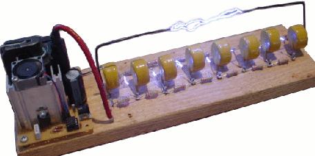
There are six stages using .002uF 20kV ceramic disc capacitors and 1Meg ohm resistors between each stage. The transformer is a 9kV 30mA neon transformer that is rectified by a string of ten 1N4007 diodes for a 10kV 1A rectifier rating. The DC charges up the generator and when it fires, makes loud 1.5-inch snapping arcs. This Marx generator fires once every 2 to 3 seconds.
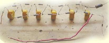

1.5″ Sparks
UPDATE! The “quick and dirty” marx generator shown above has been rebuilt in a neat manner on a small wooden platform and now runs off a compact high voltage generator. The HV generator consists of a 555 timer oscillator that drives a HV transistor, which drives a small modern TV flyback capable of providing about 12kV to 20kV. Below is a schematic diagram of the updated marx generator with the new HV generator.
The transistor I used was found in a junk pile, and if my sources are correct, is rated around 400V 8A. However, the transistor and the big heatsink got very hot while operating over 30 seconds, so I added a small laptop fan on top of the heatsink. 2.2Meg 1W resistors were used. No external rectifiers were necessary since the modern flyback already provides DC (diodes are built in). This generator fires about once every second. I could push this generator to give over 3 to 4 inch arcs, but then the resistors start arcing and the leads on the capacitors sometimes arced – so I brought the arc distance back to 2.5 inches and it performed well without problems. Below is a picture of the updated marx generator in operation (FYI: it fired twice while the camera’s shutter was open).
5C30.50 – Marx Generator
from Michigan University http://www.physics.lsa.umich.edu/demolab/demo.asp?id=860

# Note: EMP/Radiation produced by this machine can disrupt a computer, or other device such as medical electronics or personal electronic devices eg. ‘ipod’. Also any USB device input into a nearby computer can be adversly affected usually terminating the program utilizing the USB device.
# Objective:Demonstrate energy storage and discharge on small time scales, on the order of ~~ 10 micro seconds.
History and operation: The Marx generator was conceived by E. Marx in 1924. The scheme involves charging a set of capacitors in parallel and discharging them in series. Thus the operation takes a DC voltage and steps it up by a factor roughly equivalent to the number of capacitors and ‘sub-gaps’ that act as switches to connect the capacitor sections together producing a pulsed output of extremely high voltage, energy and short time frame. The DemoLab version is rated at 30KVDC input however we are running it at about 14KVDC. Since there are 10 capacitor sections, our ultimate voltage amplification should be a pulse of about 140KV. By measuring our spark gap for the maximum spark attainable, the implied voltage is closer to about 102KV. The bottom gap is set slightly less than the upper gaps and is the initiatory gap. The UV produced from the first gap helps stabilize and initiate the succeeding gaps to fire within a small time frame. The sequence of the first gap firing the second and the second cascading to fire the third etc… is called “erecting”. The erected capacitance is equal to the stage capacitance divided by the number of stages (sub-gaps). Each capacitor in our bank is about 2 nano Farad. So, the stored energy is about .225 J per section, for a total of 2.25 J for the final discharge.
# Procedure: Assure that the grounding probe is properly attached to the base plate BEFORE charging. Check that the grounding globe is positioned within 4 inches maximum of the generator output. Turn on the variac and ramp it up to 110VAC-120VAC. The HVPS should start hissing slightly, followed shortly by an explosive craaak of a high voltage discharge.
# Use Extreme Caution:Before operation of the Marx generator make all adjustments to the discharge probe/ground. After operation make sure to discharge the device with the attached grounding rod/probe.
Note also that the ground used on the generator is strictly a ‘local’ ground, and that it IS NOT in any way attached to the electrical ground from the wall outlet. If you make a connection to the wall/lab electrical ground, the voltage rise from the generator will cause electrical back feed through nearby wiring. This usually results in interesting and spectacular results, such as molten bits of sparking copper spitting from outlets and running around the table or floor and burning tracks and holes into whatever they touch, or other instruments plugged into the wall popping and sparking and refusing to ever work again. Note that connecting the Marx Generator ground to the electrical wiring ground is a potential fire hazard as well as a deadly electrical hazard. Also be mindful young padawan, that the entire Marx Generator unit is then floating, and that there is NO SAFE PLACE that you can touch it when it is operating.
# Equipment (Location http://www.physics.lsa.umich.edu/demolab/order/lablayout.htm )
– Variac
– Banana to AC line plug adapter
– High Voltage DC power supply 14 KV
– Short red and black banana cables 12″
– Marx generator
– Grounding rod
– Danger High Voltage signs
# Setup Time: 10 minutes
Demo Time: 5 minutes
Preview Time: 5 minutes
Quantity Available: 1
Birthdate: 4/28/2004
Total Demos Ordered: 14 since 4/27/2004