### German, James W.: (page created at November 2007 update)
## Generator from James W. German built and tested by Olaf Berens, bitbo@gmx.de from http://theverylastpageoftheinternet.com/ElectromagneticDev/olafberens/olaf.htm
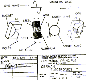
ELECTRIC CURRENT GENERATOR INCLUDING TORQUE REDUCING COUNTER-MAGNETIC FIELD.
download patent : US5191258 – click here http://goto.exit.mytoday.de/patents/US5191258/us5191258.htm
## Author Files
COMMENT: The following information is not written by me (Olaf Berens, bitbo@gmx.de) nor the pictures are drawn by my hands. This information was taken from http://www.geocities.com/ResearchTriangle/Lab/1135/german.htm
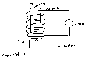
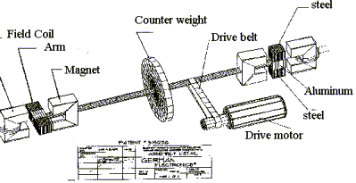
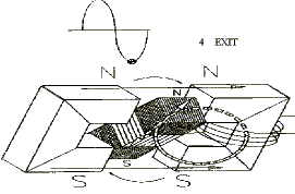
The magnet must be in one piece and has a hole drilled through the center of it to accommodate a spinning shaft.
The author also suggest put several in combination to decrease input even more.
For further info suggest you contact the author at the email address below or the postal address supplied below.
An Article supplied to this web site by James W German Rte 2, german@lcc.net
Box 2091A ; Shepherd Tx 77371-9222 ; U.S.A
# Describing his invention.
In the “lenz- test, the core of the coil is not shown, explained, or for that matter even seen as an inductor, much less, one that can be “tuned”
Standing waves will be generated with this arrangement, being a standing wave a pole of opposition will be generated.
These are the conditions the “lenz” test were done.
The pole generated at the ends of ll will always oppose the motion,
if ll is formed as part of a complete tuned circuit,
meaning providing a load for ll, generation of a pole
that will enforce the motion can be generate.
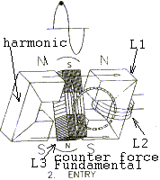
To understand this correctly, the core and the coil should be designated as l1,l2, with this in mind, if a tuned circuit were formed, the load would be l3
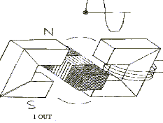
# LENZ’S LAW: The direction of an induced e.m.f. is such that it opposes the chance that produces it. for example, if a permanent bar magnet is moved towards a coil that forms part of a complete circuit, then current flows so that the magnetic field abound the coil repels the magnet, if this were not the case, no work would need to be done to cause charge to flow, breaking the principle of constant energy”
# (LAWS OF CONSERVATION OF ENERGY): this is absolute wash.
If a current is made to flow in a coil that is a complete circuit, 1 of 2 possible poles will be formed. These poles have nothing whatsoever to do with the “constant energy law”.
But rather simply a current causing an electromagnetic field to be formed that must dissipate. If you are moving a magnet towards or away from a coil wound on an iron core, but not part of a tuned circuit, a standing wave will be generated and the pole created will oppose the direction of motion.
On the other hand, if a coil is wound on a core that is a part of a tuned circuit. see diagram
If we remove the aluminum from the center part of l-3 and replace it with a nonconductor, it can be seen that a complete circuit for the counter force is not present. This will cause dissipation of the counter force on first entry of l-3. (steel ends) and not as an inductive load, resulting in the formation of poles that, will oppose the direction of motion. see diagram below.
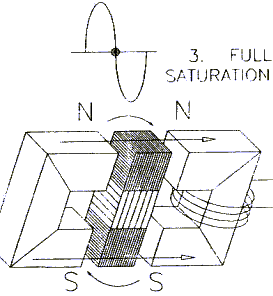
It can also be seen that if the circuit in the l-3,inductive load is not complete as a whole unit, generation of a harmonic can not occur, and with out this you can not shift poles. l-1 being the core, l-2 being the coil (e.m.f. out) l-3 being rotary “tuned load” (l/2 length of l-2) the resulting electromagnetic field will be absorbed by l-3. upon being absorbed, the generation of a harmonic will occur as well as a change of direction of the current. (180 degree phase shift) formation of the magnetic poles will occur on the harmonic.
If we remove the aluminum from the center part of l-3 and replace it with a nonconductor, it can be seen that a complete circuit for the counter force is not present. This will cause dissipation of the counter force on first entry of l-3. (steel ends) and not as an inductive load, resulting in the formation of poles that, will oppose the direction of motion. see diagram below.
It can also be seen that if the circuit in the l-3,inductive load is not complete as a whole unit, generation of a harmonic can not occur, and with out this you can not shift poles.
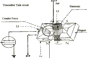
For those skilled in the art of transmitter final circuits (xmtr tank circuits) the diagram 1a below may lend some help in under standing the basic principal of operation of the generator.
Diagram 1a below has been drawn to show the “l coil” or inductors so they may be compared to that of a transmitter final circuit.
If you remove l3 and the magnet from the diagram, or cover the two with a piece of paper, and show the top end of ll connected to an antenna, and connect bottom end of ll to earth ground.
It can clearly be seen that this is a basic transmitter tank circuit. putting l3 and the magnet back in to place, and now rotating l3 through the space provided between the magnet and ll, ll being made of steel, induction will occur in l2 upon rotation of l3, and if a load is placed on l2 a counter magnetic force will be generated. with l3 being at the right place at the right time and of proper length. (aprox. 1/2 the length of ll) l3 will act as a proper load for the c.f.
As the counter force is being dissipated a harmonic is being generated that must dissipate. l3 not having an inductive path will form a standing wave at the ends of l3.
This standing wave will cause the poles at each end to be created. the poles created will add to the torque causing the motion of l3.
# The following are pages from U.S. patent # 5,191,258
You may care to use the patent searcher to view the rest of patent using the the patent server as my web site listings. webmaster
It is important at this time I make mention that the “l” designations ll-l2 and l3 are not shown on the drawing but have been added at this time to show there functions as a tuned circuit.
it is also important that i say that the U.S. patent rules would not let me show the “L” designations or make mention or reference to them as the patent process was two far along, or to put it another way, I did not enter them on the first application, and as such could not enter them at all.
thanks from Jim German
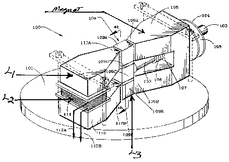
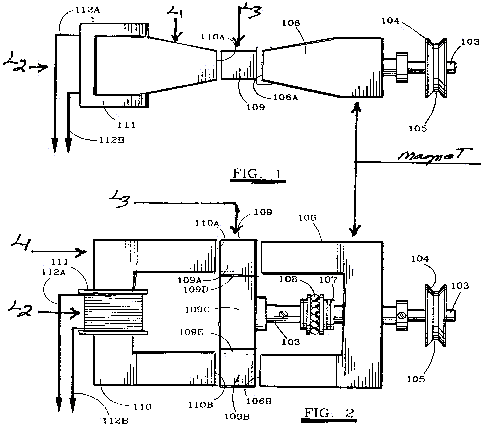
# United States Patent [19]
[541 ELECTRIC CURRENT GENERATOR INCLUDING TORQUE REDUCING COUNTER MAGNETIC FIELD
[76] Inventor: James W. German, Rte. 2, Box ; 2091A, Shepherd, Tex. 77371
[21] Appl. No.: 757,548 ; [22] Filed: Sep. 11, 1991 ; 151] Int. CI.5 H02K 1/12 ; [521 U.S. Cl 310/254;310/46; 310/168;322/49
[58] Field of Search 310/254,113,102 R, 310/46, 90, 156, 192, 264, 67 A, 138, 166, 153, 168; 322/46, 49, 50, 51, 52, 47
# [561 References Cited:
U.S. PATENT DOCUMENTS
2,218,859 10/1940 Schweitzer 322/46 X
3,261,998 7/1966 Bosco, Jr. et al 310/268 X
3,431,444 3/1969 Wilson 310/168
3.983,430 9/1976 Howard 310/168 X
4,027,229 5/1977 Frink 322/50
4,237,391 12/1980 Schur et al 322/49 X
4.385.246 5/1983 Schur et al 322/49 X
5.030,867 7/1991 Yamada et al 310/156
# Patent Number: 5,191,258 ; [45] Date of Patent: Mar. 2, 1993 ; U5005191258A (barcode number )
Primary Examiner-Steven L. Stephan ; Assistant Examiner-E.H.To ; Attorney, Agent, or Firm-Jackson & Walker
# 571 ABSTRACT: An alternating electric current generator comprises an armature rotatable carried by a drive shaft and positioned between stabilized. non-moving magnetic elements. The end armature has first and second magnetic field transmitting sections with a magnetized section sandwiched there between. As electric load is applied to the generator, a counter-magnetic field is generated through the armature to increase speed of the drive shaft and thereby lessen torque required to rotate the drive shaft.
# 1 Claim, 3 Drawing Sheets
energy conversion systems – copyright ’99 by bitbo@gmx.de
Main Menu http://theverylastpageoftheinternet.com/menu/main.htm
## Generator 1
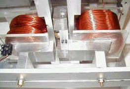
As I heard about the patent from James W. German i thought for about 3 weeks about the concept and made several diagrams and drawings to understood the magnetic flux lines and field forces. after that period of theory i thought, that it is worth to invest some money and hard work at the lathe to build a prototype for first measuring tests. in august 1999 i made the rotor and some aluminum support pieces. because of urgent projects at work it took 5 weeks until i continued at the rotor design. the rotor consists now of an aluminum disc with two 20mm holes containing soft iron cylinders with 20mm diameter and 15mm length. the magnetic field is supplied from 4 ferrite block magnets 40x20x10mm. the field goes through a 20x20mm soft iron support. a standard transformer coil collects the magnetic field from this soft iron support and generates current from the alternating field strength. a standard motor (graupner, 9,6 volt, 10 ampere) rotates the disc up to 28000 rpm. all other parts of the device are support.
from 09/10/99 until 09/12/99 i worked 23 hours to complete the device and the first test was 09/12/99 at 03:00pm.
when the device is switched on, the motor uses 10 ampere at 6 volt (60 watt) with a rotation speed of 3000 rpm.
the best result had a coil with 38 ohm. the output was 2 volt, 10 mill ampere at 100 hertz. this is not very much and because of that, it could not be checked if the input power decreases.
but this was the first test under bad conditions:
1. i was not able to vary the rotation speed to search for resonance …
2. the air gap of the rotor had to be adjusted to 20 mm, because the motor is not strong enough …
3. i used very weak ferrite block magnets
4. i used a standard voltmeter, no (true) RMS
next plans:
1. Use a bigger motor.
2. Use a variable voltage supply.
3. Use Neodymium magnets.
4. Use the shortest possible air gap.
5. Use an oscilloscope to measure the output.
(MDG nov07: Please see original webpage for full pictures)
picture 1 – overview of the device, which has not be completely assembled to be able to see some details
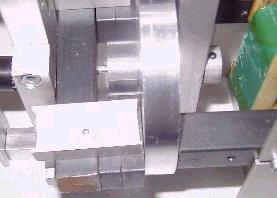
picture 2 – detailed view of the rotor, you can see here the soft iron cylinder (top of picture) pressed in the aluminum rotor and the position of the block magnets
picture3 – top view of the device, which has not be completely assembled to be able to see the soft iron square
picture 4 – back view of the device, you ca see here the two soft iron cylinder and the soft iron bar which holds the coil
picture 5 – side view of the fully assembled device,
picture 6 – perspective view of the fully assembled device,
picture 7 – detailed view of the fully assembled device, you can see here the magnets – if you can see the iron bar at the right, you may notice, that is is 4mm higher than the magnets, this is not a hidden improvement or something else – just a design-failure
picture 8 – same detailed view as picture 7 – top view. the support holding the magnets in position can be seen here, without that support the magnets wobble when the rotor rotates.
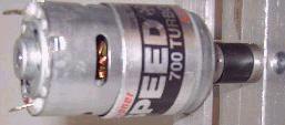
picture 9 – view of motor and transmission coupling
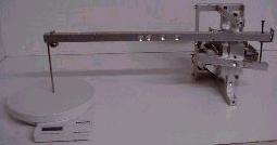
picture 10 – one view of a measurement test – here you can see a torque measurement with a digitigal balance – on the right you can see a thin long screw at which the position of the rotor could be adjusted – simple and not exact measurement, but it told me important details for the next designs
## Generator 2
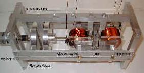
03 / 2000 ; I built a generator from the patent information of the “German-Generator” ( Inventor James W. German ) last year, which could be found at GerMagGen
That device showed not the effect of decreasing input power, while load is switched on like the inventor claimed.
Due to my test results i contacted James W. (Jim) German and asked for the failure reason. Jim German was very cooperative and sent me the complete building plans including exact dimensions, etc. from his prototype.
As soon as the plans arrived, i translated the dimensions to german (SI) units and ordered the needed parts. During manufacturing the parts i had some machining problems, which resulted in slightly different dimensions as of the plans.
Now i can CONFIRM, that the device works like the inventor claims. ( “When you put the load on, the rotation speed of the device increases, while the drive-power (motor) decreases” )
Attention: This sounds like free energy, which it is NOT and never claimed by the inventor (read patent text).
When the load at the pickup coil is switched on, that load reduces the hysteresis losses in such a way that is not understood by me at this moment. (because of that, i built the device – Jim German mentioned a standing wave). Now i will make various measurements with different loads, rpm’s, and magnetic field strength – i will post the results here.
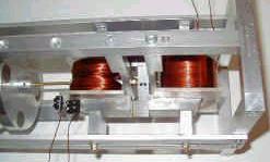
Comments: The above and below pictures show my device and not the original German-Generator. I used a coil instead of the magnet, because i first want to test if it works, before I order a special magnet for about $150. Afterwards this electromagnet seems to be better for testing purposes, because now i am able to vary the strength of the magnetic field …
Today (12.06.2000), after 12 weeks of drilling, molding, etc. i made the first quick and dirty test. (gaps are not adjusted and other things have to be optimized).
Test run 1:
– the magnet coil is switched off (no magnetic field)
– the load is not connected
– the motor is driven by 6V DC, 7,4A (RMS)
power in = 44.4 Watt (approx.)
Test run 2:
– the magnet coil is switched on ( 12V, 6A, 72Watt )
– the load is not connected
– the motor is driven by 6V DC, 11,4A (RMS)
power in = 68.4 Watt (approx.)
Test run 3:
– the magnet coil is switched on ( 12V, 6A, 72Watt )
– the load is connected (shorted, 15V, 0.420A, 6.3Watt )
– the motor is driven by 6V DC, 10,5A (RMS)
power in = 63.0 Watt (approx.)
Comments: When the load is switched on, i am able to extract approx. 6Watt from the pickup coil, while the rotation speed increases about 300rpm (from 3000 to 3300) and the power driving the motor decreases about 5.5 Watt. (conventional generators behave a little bit different – may we have here a potential for further development ?)
As i wrote above, i have to optimize the rotor, because currently i have an 1mm air-gap at both sides of the rotor. This air gap reduces the efficiency enormous ( B-H curve ).
Next plans:
1. rotor optimizing
2. shorter gap
3. real RMS measurement
4. 4-channel scope measurements
5. adaptation of trigger-sensor (for scope)
6. different operating conditions
(MDG nov07: Please see original webpage for full pictures)
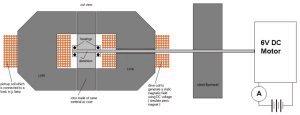
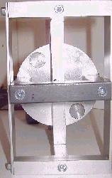
Picture 1 – Scheme of the device
Picture 2 – Overview of the device
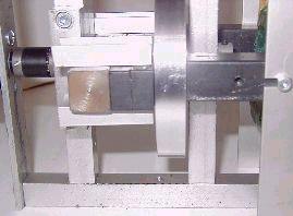
Picture 3 – Closer view of the device
Picture 4 – Close view of the device (other rotor position)
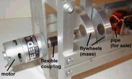
Picture 5 – Motor view of the device
Picture 6 – Top view of the device
If you have any suggestions, comments or enhancement ideas to this device, please mail to bitbo@gmx.de