### Gray, Edwin: his ‘Tube Converter’, Sparking Power Supply
See also the HV Marx Generators page zpe_marx_generator.html, and the page Spark Gaps zpe_sparkgap.html
## The Complete Patents of Nikola Tesla http://www.luminet.net/~wenonah/new/tesla.htm
# The Original Discovery of ‘the Sparking Radiant Effect’ (moved to page 2 about Gray’s Sparktubes, see menu above))
## From Captain Patrick Kellys’ files:: http://panacea-bocaf.org/files/patrickkelly/D1.pdf
# Grays’ patents reworked by P. Kelly:
– Gray snr.’s electric motor patent 3,890,548 http://panacea-bocaf.org/files/patrickkelly/PatD2.pdf
– Gray snr.’s electronic circuit patent 4,595,975 http://panacea-bocaf.org/files/patrickkelly/PatD3.pdf
– Pictures and information http://www.keelynet.com/evgray/evgray.htm
– Background information http://www.rexresearch.com/evgray/1gray.htm
## Ed Grays Power Conversion Tube, courtesy John Bedini – 06/05/01
Peter Lindemann has discovered an important connection between the mysterious power conversion tube patented and used by Ed Gray with his high voltage pulse motors and Teslas use of unidirectional pulses to produce a wide range of phenomena as detailed in his new book and video which are available on his website. Additionally, Peter has posted many historical files about Gray, Tesla and other correlations to get the ball moving to try to rediscover and duplicate the phenomena demonstrated by Ed Gray.
This file has the majority of information provided through the courtesy of John Bedini who met EV Gray, studied his power converion tube and built this tube which is shown below with construction details. John’s website is listed below and you can click on his name if you want to email him with specific questions. Bedini has built many motors over the years and has freely posted the design and construction details on his website. He has always shared information on the intricacies of building not only high efficiency motors but in some cases, motors which recharge their batteries while sustaining loads as has recently been reported in Tennessee. http://www.escribe.com/science/keelynet/m10396.html . Peter will be lecturing on this subject in his ‘World of Free Energy’ presentation at the KeelyNet Convergence conference on June 16/17, 2001 in Dallas as posted at http://www.keelynet.com/knconf.htm .
Two of the original Ed Gray motors will also be shown by Norman Wootan and another pulse motor developed and demonstrated by Doug Konzen (who uses the screen name ‘Konehead’). The following series of email exchanges are from the KeelyNet Interact discussion list as so very kindly shared by John Bedini and Robert Calloway. John further ripped the veil of secrecy on the power tube by sending his 1979 experiment photo and lab notes for everyone to study.
 –
–  – –
– –  –
–  –
– 
# From: Jerry W. Decker jdecker@keelynet.com ; To: John Bedini john1@icehouse.net ; Sent: Friday, June 01, 2001 9:21 PM
Subject: yep, we dragged you into it… http://www.escribe.com/science/keelynet/m10194.html
# From: Jerry W. Decker ; To: interact*keelynet.com ; Sent: Saturday, June 02, 2001 7:50 AM
Subject: [Keelynet] Re: Lindemann on the World of Free Energy
Hi Folks!Received the following from John Bedini regarding Grays coils, the power conversion tube and what is going on with the motor;
john1 wrote: Jerry – You can drag me into this all you want, The answers have been given to everybody, every time I posted something with you, AS I SAID BEFORE THERE IS NO SECRET TO GRAYS MACHINE I DO NOT KNOW WHAT IS SO MAGICAL ABOUT A HIDDEN TUBE THAT GRAY HAD. I have given Peter the lab notes from my files on gray’s tubes when Ron and I went to visit him . Peter came to visit Me he knows what I can do with My machines. I asked him kindly to not say anything that I was working on, this was my own request until I’m ready.
Back to gray’s tube and motor. I have given peter My lab notes on this tube He has my permission to do anything he wants with them. Peter has given you all the answer not only in his book but in your discussion group, but once again, “WE ARE ALL BLIND”.
He has said to you all in the group it’s how you capture the energy!!!!!!!!!!!! What is so hard for you all to understand. It’s almost like we do not speak the same language. Now to the real stuff…
First of all the motors shown on the internet are something different Gray was working on. “””””” THE COILS ARE NOT THE SAME AS THE MOTOR I HAVE SEEN IN THE EARLY DAYS”””””””” what does this say to everybody??????
Can anybody answer Me as to how these tubes work,,, NO BECAUSE YOUR LOOKING FOR THEM, YOU WON’T FIND THEM, and no one can make them if you do not understand them. TESLA USED THE SAME TUBES THAT RAN HIS CAR!!!!!!!!!!.
I have also said that the school girl motor gave all the answers to the problem of free energy. Their is not going to be any kit that somebody can buy at radio shack, Research into this field takes real hard work. The Swiss machine uses the same tubes, WHY BECAUSE THIS IS THE ONLY WAY TO CHANGE THE FORM OF ENERGY TO SOMETHING USEABLE.
Splitting the Positive what does this mean, it means that one lower form of positive energy is transformed into a higher form, but they are the same potential energy except useable now to do work “REAL POWER IN WATTS” or if you would say AMPS times VOLTS.
I have made he statement to you before about the way everybody gets the FLUE the stuff that makes you sick, you just don’t just get it, takes “TIME” Time is the key factor in pulsed motors(“”” GRAY”””)….
IT TAKES TIME TO STORE THE CHARGE TO SOME POTENTIAL BEFORE YOU CAN USE IT FOR DISCHARGE into something. Into something meaning a storage battery or some load that the meters can measure. Closing the loop YOU CAN’T, free energy does not work this way, loops are never closed in any machine that’s over unity.
THE TWO ENERGIES ARE DIFFERENT because the two POSITIVES ARE DIFFERENT they are at the same potential but one weak, one collected and strong in discharge . Stored charge, Time, discharge to something , no closed loop, these are the keys to free energy , and it’s not free you must work to get it. By the way the motor runs without the tube, just a little stronger with it and time delayed.
Someone answer how the tubes work and we will have a real discussion on Gray, and then comes a picture of a pro-type tube taken with a digital camera that I built some time ago for a different machine. And you can post this..
John
# [Keelynet] Re: Lindemann on the World of Free Energy ; From: Robert Calloway ; Date: Mon, 4 Jun 2001 21:53:21
Hello Jerry and all, Having spent countless hours studying and building John Bedini’s motors, I think some confusion exists between John’s explanation of what is not being understood and Tom Bearden’s explanation of what is going on in these motors.
This email is not intended to debunk either one of them, only to try and explain how his design of motor works from my point of view.
If one has never built a pulsed motor you will not realize what is being overlooked until having done so. S1 has always held the secret in John’s schematics, and I followed right along behind him in my drawings.
If you place a arc gap at S1, a increase in voltage occurs. If you collect S1 in a capacitor and time it to discharge into ANOTHER battery via a arc gap (getting it out of the loop) the potential is multiplied.
How much is how long you TIME the wait. What some fail to see is these motors use sparse milliamps to run compared to the output at S1 if stored in a capacitor and TIMED to release through the arc gap into a different battery.
THAT’S THE SECRET. John shows this in several of his schematics everywhere on the web. If you release the stored energy in the capacitor back to the working or same battery, the excess will “ghost”, you will never see it.
John has got it very correct..STORED CHARGE, TIME, DISCHARGE, NO CLOSED LOOP. How this happens? I don’t know, but it works.
S1 shown at: http://www.keelynet.com/bedmot/callow1.htm ; Regards, Robert H. Calloway
# From: Jerry W. Decker ; Date: Tue, 5 Jun 2001 00:29:08
Hi Folks!John Bedini wrote this about Robert Calloways post, rather flattering to Robert methinks…he wanted it posted to the list so here it is;
john1 wrote: Jerry – This is the best I have seen, Robert has got it so you guys win the tube and how it works, Robert is right now it’s time to understand how you get the energy, the energy is produced in the back EMF or the spikes only , but they are not useable until they are converted by the cap for discharge into a secondary battery but at the right time.
So here it is EV Gray, He knew this so He had to developed a different standard A new motor with more inductance in the coils , No re-charge coils are needed because the power coil supplies all the energy in spikes, You know the thing every engineer shorts out with diodes because it burns out their circuits. You can produce free energy any time if simple rules are followed.
Their is no hidden trick here. depending on how much energy is needed this is all timing to produce the correct voltage level for discharge into the battery, I have said you can not close the loop so therefore the 1 watt challenge is out and has no meaning except to confuse everybody and through you off the track.Robert is right in saying that you are just “”Ghosting”” to feed back to the same battery.
The Tube : If you study the EV Gray tube you will see that the tube uses two electrodes, a high voltage electrode and a low voltage electrode the low voltage side is on the primary battery and the high voltage side is on the 3000volt side when a arc is drawn from the timing rotor this completes the circuit between the two positives, one from the inverter and one from the battery positive all grounds are connected to the same point. now subtract the differenceof the twelve volts and you have the real voltage or 2988 volts, but this is high voltage and can not be used so the conversion takes place in the tube on the grids.
The ARC is emitted electrons (which) fly off the electrodes and get stored on the grids this is the cold Electricity Gray talked about and how it was collected.
If this is true then an antenna connected to a coil of so many turns is rectified and stored into a laden jar cap.
The gap on the tube is set to say 1/32, when the discharge takes place the cold electricity sent out through the grids to the storage battery you are charging and you do this for free. And you did not close the loop to short it out.
Gray was too close to providing the world with free energy with just an antenna of any kind,,,,,, SO THEY KILLED HIM.
So we have the Swiss machine that works the same way, we have Grays Machine , and we have the car that Tesla built that works the same way. They all use the same tube just different variations.
You can make this anyway you want to experiment with, I used this as a medical machine with light currents for treatment with one electrode.
Good going Robert, Have fun. – John
Try this experiment, take three flashlight batteries put two on one side in series and one on the other side connect the two negatives together, now between the two + poles connect a light, this is splitting the positives.This has been on my pages forever, but nobody unerstood it. Jerry please post this for the group.
# Subject: Re: [Keelynet] Re: Lindemann on the World of Free Energy] ; Date: Tue, 5 Jun 2001 00:51:16 -0700 ; From: john1 ; To: Jerry W. Decker
Jerry – You do what you want with the picture, this tube is very hard to make requires milling machine to do and no it’s not My version It’s grays tube this is what was hidden inside of the Swiss machine and what Tesla used also Gray I will send you the lab notes, but I’m sure Peter will give them to you.
Robert is the one, He did real good in the answer. post the tube if you want these tubes are about 3″ in diameter grid spacing is 1/4 ” between grids 5″ long 1/4 inch brass rods with silver gaps.
## Summary:The mechanism of the electric spark http://www.pureenergysystems.com/os/EdGrayMotor/PM_PEM_MG/theory/spark/mechanism_electrical.htm
by: Leonard B Loeb, Professor of Physics ,University of California at Berkeley; and John M Meek, Research Engineer; Publisher: Stanford University, Calif., Stanford University Press, 1941.
“This was the first real monograph you could get hold of on sparks.” (IEEE http://www.ieee.org/organizations/history_center/oral_histories/transcripts/pederson.html )
Preface Comment
From: Gary Magratten ; To: Sterling D. Allan ; Sent: Friday, June 04, 2004 6:30 PM
Subject: Mechanism of the Electric Spark, Pupoff and Mark McKay
Dear Sterling,Attached is the summary of ” The Mechanism of The Electric Spark” by Loeb and Meek. The work of Loeb and Meek basically states that in a spark gap exposed to open air consisting of a simple cathode and anode, there is a huge current gain due to avalanche. The work of Loeb and Meek is significant for two reasons; 1)During the ionization of air molecules into positive ions and negative ions, (free electrons) a quanta of EMR is required to liberate each electron.
When the free electrons are absorbed by the high voltage anode the free electrons become bound again, and give up a quanta of electromagnetic radiation. Because of the huge increase in free electrons developed in avalanche the amount of EMR given off by the high voltage anode is in the range of hundred to thousand fold increase. Thus the huge “Radiant Event”.
2) In both circuits the current from avalanche is recycled back to the primary battery and the secondary battery. Please look at the circuit and trace the path. Thus a never ending supply of current. Loeb and Meek were professors of physics at Berkeley and their work is well established by many test.
When Mark [Mckay] and I were first doing research on the Gray Circuit we (especially he) kept blowing up components. It was a year before I read the rare book by Loeb and Meek that explained why the components were blowing up. There was a current gain of 500% with the open air, high voltage spark gap.
The use of steel for the high voltage anode is also critical to a large ‘Radiant Event’. I (believe) that the magnetic properties of steel play an important role in the release of this energy.
Keep up the good work! Gary Magratten
‘The Mechanism of The Electric Spark’, by Loeb and Meek
The Generation of Electric Power by High Voltage Avalanche. Also available in PDF with formatting from www.faraday.ru http://www.faraday.ru/14-37.pdf “Excessive Output by Means of Air Ionization: The Mechanism of the Electric Spark”
Dedicated to: Professor J. S. Townsend ; Whose pioneer research and theory laid the whole foundation for the study of the mechanism of the electrical spark discharge.
# Preface
Although the electric spark has been known to mankind in its various manifestations from time immemorial, its mechanism has to date been little understood. The initial clarification of the mechanisms involved is due to J.S. Townsend as a result of his brilliant researches in the early nineteen hundreds. On the basis of his theory of ionization by collision by electrons and positive ions, the fundamental mechanisms active and especially the coefficients required in their application were made available.
In 1936 the present senior author was forced to describe the mechanism of spark discharge in terms of a modified but distinctly unsatisfactory Townsend theory. In 1935 the discovery of photo-ionization in air by corona discharge indicated a solution was not far off. The turning point of a more successful theory came in the discovery of streamers in positive point to plane corona in 1936. The quantitative analysis of the self-propagating positive streamer in all breakdown phenomena became clearly evident as a result of the data concerning electron avalanches. As a result a qualitative mechanism of sparking by streamer propagation from anode to cathode functioning by means of photo-ionization in the gas was established.
# The Townsend Sparking Criteria
It will not be necessary here to derive the famous equation of Townsend for the current [i] in a gap between electrodes as a function of the photoelectric current [io] from the cathode, the gap length [x] and the coefficients [a] and [B]. For this the reader can go to any standard text.
In this equation the first Townsend coefficient [a] represents the number of new electrons created in the gas by an intial electron in its advance of 1 cm along the field axis from the cathode. The second Townsend coefficient [B] in Townsend’s original theory was the number of new electrons created by a single positive ion in its advance of 1 cm along the field from the anode.
The quantity [a] has been extensively studied in various gases. It varies with the ratio of field strength to pressure, X/p, where [X] is in volts per centimeter and [p] is in millimeters of Hg.
note: the reason we are going through this is to determine the actual increase in current provided by the spark gap, and thus be able to design the circuit to avoid blowing out semiconductor components.
It also provides a sound and already proven scientific theory to work from giving us a good foundation and the confidence to proceed with technical design work.
The quantity [B] has been evaluated, albeit rather inaccurately, from the variations of [i] with [x] at various higher values of X/p, by many observers indifferent gases. Inasmuch as it has now been shown that there are numerous other mechanisms other than impact with positive ions which can liberate the secondary electron needed in discharge.
There has been an inclination to give up the mechanism of impact ionizations by positive ions in gas. The discovery of measurable photoelectric ionization in gas has now made it possible to explain such cases.
The exact way in which photo-ionization in the gas could operate to cause a spark, was not clear until the development of the present streamer theory.
Two of these equations are given below, together with Townsend’s original equation for comparison.
Equation 2 is one for the liberation of secondary electrons at the cathode by positive ion bombardment. I this equation [y] is the chance that a positive -ion will liberate an electron from the cathode on impact.
Equation 3 is the equation for liberation of electrons by photoelectric action at the cathode.; [Q] is the number of photons created per centimeter path of advance of an intial electron from the cathode. [g] is a geometrical factor .5. which depends on the fraction of photons reaching the cathode. [n] is the fraction of the photons reaching the cathode that succeed in actually liberating electrons from the cathode so they do not diffuse back. [u] is the absorption coefficient of the photons in the gas.
# The Streamer Theory of Spark Discharge Anode Space-Charge Field Due to an Avalanche
Assume a spark gap of 1 cm in length. Assume that in air at atmospheric pressure the potential across the plates is 31,600 volts, which is the conventionally observed sparking potential [Vs]. Let us then calculate what happens in the field to one of those electrons. It starts across the gap, quickly acquiring an average random energy of some E=1/2mC2= 3.6 electron volts and a drift velocity [v] in the field direction of about 1.5 to 2 times 10(7) centimeters per second. As it moves it creates new electrons at a rate of [a] per centimeters in the field direction so that in a distance [x] it and its progeny amount to e(ax) electrons, forming what is called an electron avalanche.
Therefore, e(ax) positive ions have been left behind by the electron group, virtually where they were formed in the 10(-7) second of advance for the electrons in the distance x=q across the plates. As the electron avalanche advances, its tip is spreading laterally by the random diffusive movement of the electrons.
From these data it is possible to compute the density of positive-ion space charge left behind at any point [x]. The value of [a] under these conditions is about 17, making e(aq)=e(17). The first ion pair is created at .0407 cm from the cathode. At .5 cm from the cathode there are 4914 ions, at .75 cm there are 3.66 times 10(5) ions, and within .0407 cm from the anode there are 1.2 times 10(7) ions. Most electrons will be drawn to the anode except for some few that are bound by the positive ions, making a sort of a conducting discharge plasma in the avalanche.
Such a distribution of ions does not make a conducting filament of charges across the gap, and hence in itself an avalanche that has crossed does not constitute a breakdown of the gap. Thus one must look further for the mechanism of the spark.
If Loeb and Meek are correct then if we assume a spark gap of 3 mm and a voltage of 5,000 volts there are roughly 2,000 electrons created by avalanche for every one electron leaving the cathode.
They state that most of these ‘free electrons’ are absorbed by the anode.[This would certainly explain why the semiconductor components can not handle the current gain.]
NOTE: Loeb and Meek make little reference to initial amperage. There are only two values they refer to 10(-5) ampere and 10(-12) ampere.
In conclusion: Sparks and Arcs are two different beast. My initial research into the amperage necessary to form an arc does not apply to spark and the process of avalanche where this huge gain mechanism is possible.
# Photoelectric Ionization in Gas as a Secondary Mechanism
Accompanying the cumulative ionization there is produced by electrons from four to ten times as many excited atoms and molecules. Some are excited to an energy exceeding the ionizing potential of some of the atoms and molecules present, either by excitation of an inner shell, by ionization and excitation, or in a mixed gas like air by the excitation of molecules of higher ionizating potential, e.g., N2. These excited atoms or molecules emit radiations of very short wave length in some 10(-8) second. This short ultraviolet radiation is highly absorbed in the gas and leads to ionization of the gas. In fact, the whole gas and the cathode as well are subjected to a shower of photons of all energies traveling from the region of dense ionization with the velocity of light. Thus nearly instantaneously in the whole gap and from the cathode new photoelectrons are liberated which almost at once begin to ionize cumulatively.
# The Mechanism of Positive Streamer Formation
The photoelectrons created at points in the gas and at the cathode at any great radial distance from the avalanche axis will merely create other avalanches.
Those in the gas will be short and those coming from the cathode region will be long and like that of the initial avalanche. Being smaller and, in any case, later in creation than the parent avalanche, such avalanches will be of no interest in breakdown. However, those photoelectrons created near the spave-chargechannel of positive ions, and especially near the anode, will be in an enhanced field which exerts a directive action drawing them into itself. If the space-charge field [X1] is in the order of magnitude of the imposed field [X], this action willbe very effective. In addition the values of [a] will be much enhanced.
The electrons from the intense cumulative ionization of such photoelectron avalanches in the combined fields [X] and [X1] which are drawn into the positive space charge feed into it, making it aconducting PLASMA which starts at the anode. The added fields will be most effective along [X] and so will the ionization. The positive ions they leave behind will therefore extend the space charge towards the cathode.
These electrons also create photons which produce electrons to continue this process. In this fashion the positive space charge developstoward the cathode from the anode as a self-propagating positive space-charge streamer.
As the streamer advances towards the cathode it produces a filamentary region of intense space-charge distortion along a line parallel to the field. The conducting streamer of a plasma consisting of electrons and ionsextending to the anode thus makes a very steep gradient at the cathode end of the streamer tip. As this advances toward the cathode the photoelectronavalanches produced by radiation at the cathode, especially at the interceptof the extended streamer axis at the cathode, begins to produce an intenseionization near the cathode. Hence the positive ions created there may increase the secondary emission. Thus, as the space-charge streamer approaches the cathode, a cathode spot is forming which may become a source of visible light. When the streamer reaches the cathode there is a conducting filamentbridging the gap. As the streamer tip reaches the cathode the high field produces a rush of electrons towards the end of the streamer. This if followed by a current of electrons, gives a high-potential wave which passes up the preionized conducting channel to the anode, multiplying the electrons present by a large factor. The channel is thus rendered highly conducting.
If the metal can emit a copious supply of electrons because of the formation of an efficient cathode spot, the current of electrons continues the channel maintaining its high conductivity and ever increasing in it. This current , unless limited by external resistance, will then develop into an arc. It is, however, the intense increase in ionization by the potential wave which gives the highly conducting channel characterizing the spark.
## Power Supply Suitable for Inductive Loads, by G.M. http://pureenergysystems.com/os/EdGrayMotor/PM_PEM_MG/prototypes/powersupply/GM1/index.html
Prototype #1, June, 2002
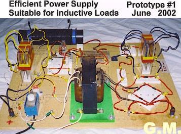
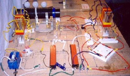
Image Description by Sterling D. Allan ; May 29, 2004
Working device by G.M.. Close to Gray’s patent 4,595,975 http://pureenergysystems.com/os/EdGrayMotor/PM_PEM_MG/patents/4595975/index.html , except that Gray used a “closed tube,” while G.M. uses an “open air” tube. G.M. will also be specifying exact components, whereas Gray’s patent is not that specific. G.M. had to make a “wild guess” on this prototype, based on a Technical Report by Richard Hackenberger and an understanding of the “high power pulse” principle.
G.M. said that this power supply output was “too powerful for bench top type work,” so he scaled it down in prototype 2. The above first prototype was disassembled for space considerations to make way for the next iteration. The second, smaller prototype is presently working. Images pending. Prototype 1 used purely opposing permanent magnets. Prototype 2 uses a combination of electromagnets and permanent magnets.
# Addendum Comment by G.M. Associate — HV System Clarifications
From: “Mckay, Mark” mmckay@tycoint.c* ; To: sterlingda@pureenergysystems.c* ; Sent: Tuesday, June 01, 2004 5:24 PM
Subject: Pure Energy Systems, Director of Administration contact – Suggested Addendum Information to GM Photo
Dear Mr. Sterling [Allan], In the photo of Mr. [G.M.]s EV Gray Power supply/conversion tube it would be most helpful to point out to your readers that the 5000V Main power Transformer is driven by a 660Watt Triac Light dimmer. The primary 120VAC input is severely disrupted and is no longer a sine wave. This approach seems partially consistent with some parts of the HV system that Gray used in that a DC vibrator excited ignition coils (according to the Patent documents).
Also the homemade glass capacitors that Mr. [M] used has a measured value of 140 micro-micro farads, several orders of magnitude less that the 2mfd (or 12 mfd) that was allegedly used by Mr. Gray as a storage device. These variations used by Mr. [M] may be significant.
I just thought these two technical details would help your readers in their understanding of this un-disclosed technology.
Keep up the good work. I shall enjoy reading all of your postings. Mark McKay, PE ; Spokane, WA.
# Note About Transformer
From: “Mckay, Mark” ; mmckay@tycoint.c* ; To: Sterling D. Allan ; Sent: Thursday, June 03, 2004 4:49 PM
Subject: RE: Pure Energy Systems, Director of Administration contact
Dear [Mr.] Allan, Another minor technical point about [G.M.]’s power transformer. The Transformer shown in the photo was custom made. Gary was able to secure it originally for $183.00. In requesting a quote from the same company the price had risen to $660.00 (in 2002). I’m sure the price is even higher with the increase in copper costs. It is a pretty hefty device. I believe (with out referring to notes) that it was rated at 500mA current at 3000V (or so) about 1.5KVA.
I look forward to reading the technical paper by Mr. Hackenburger (see Gray EMA motor page of this website, menu on top).
According to Mr. Norm Wooten the original EV Gray technology came from a Mr. Popoff whom Mr. Gray worked with during his employment with NASA. From other knowledgeable authorities in the field, Mr. Popoff is allegedly to have had direct contact with Dr. Tesla during his declining days in New York. Do you happen to have any further information about Mr. Popoff?
Mark McKay
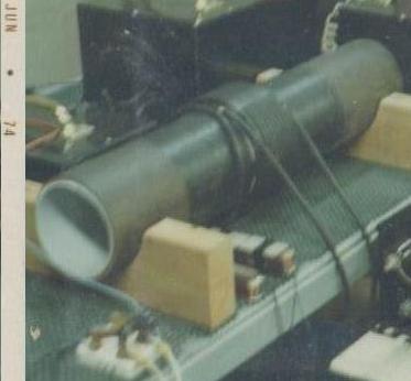
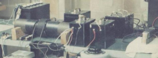
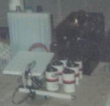
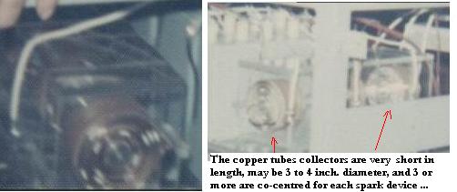
## Exclusive pictures about Gray’s sparking tube and motors EMA, made by G.T. Durnford, in 1974, 75 and 76, form the files of the Yahoo Group : http://tech.groups.yahoo.com/group/alfenergy/
Here some extracts about ‘the Gray sparking amplifier tube’:
## Efficient Power Supply Suitable For Inductive Loads — Engineering Report Gray Patent No. 4,595,975, Commentary by Gary Magratten http://www.pureenergysystems.com/os/EdGrayMotor/PM_PEM_MG/plans/proto1GM/index.html
Originally Published by Energy21 ; Reproduced here to protect the contact info of Mr. Magratten
Note June 13, 2004 (about a year after the Energy21 publication): Gary claims to have recently successfully replicated a variation of this design, including the laser diode switching.
# Preface Comment, by Gary Magratten, June 13, 2004
From: Gary Magratten ; To: Sterling D. Allan Subject: Power Supply for inductive Loads , ER
Dear Sterling, Posting the ER on the power supply is just fine. It was intended as a starting place for R&D. There are many corrections and updates to that work as my knowledge about triodes, pulsed dc driver circuits, avalanche and transients has increased.
When I finish with the present PM/PEM, M-G project of making it available for market. I would like to make corrections and additions to this ER to save others time.
G.M.
# INTRODUCTION
The purpose of this report is to provide the circuit analysis, working drawings, component specifications and component manufactures for Mr. Edwin Gray’s patent number 4,595,975 – Efficient Power Supply Suitable for Inductive Loads.
This information is for SCIENTIFIC RESEARCH only in order to more fully understand the scientific principles demonstrated by Gray’s pat no. 4,595,975.
In the spirit of open information and cooperation between scientist, researchers and business professionals, this information is open to the public and may be reproduced and distributed by anyone for the purpose of providing scientific research information
WARNING! Gray’s Circuit pat. no. 4,595,975 contains a very HIGH POWER CAPACITOR that is DANGEROUS! Experimentation with this circuit requires at least the formal education of a licensed electrician.
If you perform research with this circuit, YOU DO SO AT YOUR OWN RISK. Follow all standard safety precautions and use a proper laboratory to conduct testing.
If you follow the instructions, the circuit will work. I have confirmed this with actual test runs. It is my sincere hope that clean, efficient means to generate electricity will evolve from this information for the benefit of everyone.
Mr. Gary Magratten
# Circuit Section 1. Battery to transformer:
Working Drawing #1
The batteries should be deep cycle golf cart batteries, 12 volts and under 200A hrs Use true deep cycle batteries. Automotive batteries are designed for high current for a short period of time. Deep cycle batteries provide steady current and can handle repeated recharging. A deep cycle battery rated at 200 A hrs should deliver 10 amps of current for 20 hrs.
There are three ways to accomplish this section of the circuit. Working drawing no.1 show all three ways. First, and easiest for research is the use of 110 AC house current at iS amps to the primary of a transformer and a 3,000 volt, .5 amp AC secondary. The second is a 12 volt battery, DC, to a chopper-vibrator which produces 12 volt AC for the transformer.
The design of the chopper-vibrator will be described separately later. This requires a special transformer with a 12 volt AC at 100 amps to the primary. The primary side also requires a center tap. The secondary is 3,000 volts and .5 amps AC. The third, is to use a deep cycle battery 12 volts, 100 amps and an inverter to form 110 AC at 11 amps. The transformer should then be rated at 110 volts at II amps on the primary and 3,000 volts and .4 amps. Include a switch and a fuse into the circuit as shown on the working drawings.
Working Drawing #2
# Circuit #2 – Transformer to Full Wave Bridge:
From the secondary of the transformer there is 3,000 volts and .5 amps alternating current. The full wave bridge converts the alternating current to direct current pulses. Position the diodes of the bridge for a positive terminal close to the transformer and the negative terminal away from the battery. To build a full wave bridge you can use four diodes or a one piece full wave bridge unit. The rating of the diodes is 8,000 PIV (peak inverse voltage) and .5 amp forward current.
Working Drawing #3A
# Circuit Subsection 3A. – Full Wave Bridge to the Capacitor #1:
In subsection 3A the full wave bridge can be treated as a direct current source with a positive terminal and a negative terminal. The voltage available is 3,000 volts at .5 amps. The positive terminal of the full wave bridge is connected to the positive side of Capacitor #1.
The negative terminal of the full wave bridge is connected to the negative side of Capacitor #1. The positive terminal of the capacitor is directly connected to the high-voltage anode of the CSET.
The negative terminal of the battery is connected to the negative terminal of the full wave bridge. Then the negative terminal of the full wave bridge is connected to the negative side of Capacitor #1.
THIS IS VERY IMPORTANT. THE 3,OOOvoIts 0.5 amp DIRECT CURRENT IS COUPLED WITH THE l2volt, 100 amps AVAILABLE FROM THE BATTERY. THIS GIVES A 300 Kva CHARGE TO CAPACITOR #1. THIS IS VERY HIGH POWER and DANGEROUS!
I found this difficult to understand but the technical discussion from Mr. Richard Hackenburger ( Mr. Gray’s electrical engineer clearly shows ZS6Kva of instantaneous power available from Capacitor #1.) Careful examination of the wiring diagram will confirm this statement. Pulses of direct current are built up (technically called RAMPING) on capacitor #1 to be available for the arc in the CSET.
CSET:
# Circuit Subsection 3B
Capacitor #1 to the high-voltage anode of the CSET. The positive side of Capacitor # 1 is coupled directly to the high-voltage anode of the
CSET. Use #10 stranded copper wire with standard insulation and electrical tape to prevent contact with this HIGH POWER section of the circuit. The high-voltage anode is 3/16″ zinc plated steel rod. This will be discussed in detail in the CSET section.
Working Drawing 3B
Circuit Subsection 3C. From the collector grids of the CSET to the Load to the plate of Capacitor #2.
THIS SECTION IS UNUSUAL AND THEREFORE DIFFICULT TO COMPREHEND, PLEASE HAVE PATIENCE!
The wave form of this section of the circuit is very unusual. This may be what was termed “Cold Electricity”. I have to do laboratory test to verify this explanation. Circuit Subsection 3C extends from the collector plates in the CSET to the Load to the Capacitor #2.
The LOAD and the CSET will be treated a separate subjects. The collector plates are exposed to the high-voltage anode 3,000 volt positive potential when the circuit switch on the low voltage side of the CSET is open. The 3,000 volt positive potential draws electrons to the collector plates from the circuit.
When the switch is quickly closed then reopened [.00005 sec] an ARC forms in the spark gap between the low voltage anode’s available current and the high voltage anode 3,000 volt positive potential. When an ARC is formed it is commonly accepted knowledge that the atmosphere is ionized to form positive ions and negative ions[ free electrons].
When the ARC occurs, The Electrons Give Up Quanta or Photons of Electromagnetic Radiation. This is evidenced by the flame like discharge of visible light. This release of EMR or Radiant Event induces a current in the collector plates. This is the Photoelectric Effect to which the discovery is accredited to A, Einstien, The ARC charges the copper tubes( collector grids 34A and 34 B ) at the end near the spark gap.
The charge moves down the tube to the wire that is located at the end of the collector plates and then to the load, At the same time, the collected free electrons are absorbed from by the high voltage anode. As the BUNCH of electrons move down the steel rod, high voltage anode, the 3,000 volt positive potential is negated.
This releases the electrons in the collector plates manifesting a greater flow of electrons into the collector plates and thus the circuit. Please visualize this slowly, and step by step.
Once again the switch is open and the 3,000 volt positive potential returns to the high voltage anode, and the process begins again.
Think of the circuit that extends from the collector plates through the LOAD to the Capacitor #2 plate as a column of fluid in a pipe, that is first stressed or subjected to suction, then compressed by pressure, in a repetitive manner. in the same manner the circuit is stressed then compressed with short duration, high-voltage, high-current energy spikes.
A single energy spike is capable of repelling like charged electromagnets with great force. This is how the motor was powered.
As the instantaneous energy spike travels through the load an EMF is produced about the inductor, be they electromagnets or a transformer.
When the energy spike ceases, the EMF is absorbed back into the inductor and on to the Capacitor #2 which is a coupling capacitor in that it draws current from the positive terminal of the battery thus recharging the battery.
Working Drawing 3D
# Circuit Subsection 3D. From Capacitor #2 to the Battery.
This section of the circuit extends from the plate of Capacitor #2 to the positive terminal of the battery. According to the patent the CEME is transferred through Capacitor #2 to recharge the battery.
I am going to propose a slight change in the design. This is the only place where I deviate from the patent and the schematic as originally presented.
[I would also like to state that during my efforts to reconstruct this circuit, I wasted a many hours trying to second guess the information and take short cuts. The message here is to follow the patent and the schematic, the device does work.)
The change in the design is the introduction of a diode from one plate of the capacitor to the other with the forward current flow in the direction of the LOAD. I have NOT TESTED THIS YET. Here is the reason for the proposed change in the design. Capacitor #2 is a coupling capacitor in that it conducts alternating-current but blocks the transmission of steady direct current. For the sake of analysis let us say that pulsed direct current can be treated the same as alternating current with respect to the capacitor#2 in that the changing value of voltage and current are coupled through the dielectric.
When the low-voltage switch of the commutator is open, no power is flowing in the circuit. The high-voltage anode is at a charged state of 3,000 volts. This draws electrons to the collector plates from the plate of the capacitor #2.
The deficit of electrons on Plate C of the capacitor#2 becomes a positive potential. The plate B of capacitor #2 becomes negatively charged by drawing electrons from the positive terminal of the battery. This is the same way a battery charger works.
By introducing a high current diode from plate B to Plate C of Capacitor#2, a one-way-path is created for the current drawn from the positive terminal of the battery.
When the commutator switch is closed and power is flowing in the circuit an ARC is created from the low voltage anode to the high voltage anode. This ARC [EMR or Radiant Energy] is absorbed by the collector grids 34a and 34b.
This pulse of power induces a spike of energy [high-voltage, high-current, short duration pulse I through the wire back to plate C of capacitor #2, which had a positive potential.
The power pulse arrives on the plate C and distributes electrons on the plate. These electrons can travel no further than the plate because the diode prevents the transfer of electrons to plate B.
The commutator switch is opened and the high-voltage potential returns to the high-voltage anode of the CSET.
The cycle repeats itself and electrons are drawn to the collector plates by the high positive potential of the high- voltage anode. The introduction of a HIGH CURRENT DIODE from plate B to plate C creates a one-way-path for current to be drawn from the positive terminal of the battery to allow the battery to be recharged.
Working Drawing 4:
# Circuit Section 4. Battery Charging Circuit.
THIS SECTION IS NOT EXPLAINED BY THE PATENT. SIMPLY TRACING THE CURRENT FLOW WIll VERIFY THIS ANALYSIS.
The battery charging circuit extends from the positive terminal of the battery through the commutator; through the triode; to the low voltage anode; across the spark gap; to the high voltage anode; to DIODE 46; to the negative terminal of the battery.
IT IS CRITICAL TO THE UNDERSTANDING OF HOW THIS CIRCUIT WORKS TO COMPREHEND THE DIRECTION OF CURRENT FLOW IN THIS SECTION OF THE CIRCUIT! THE CURRENT FLOW IS FROM THE POSITIVE TERMINAL OF THE BATTERY THROUGH THIS CIRCUIT TO THE NEGATIVE TERMINAL OF THE BATTERY! THIS IS OPPOSITE THE NORMAL DIRECTION OF A DIRECT CURRENT CIRCUIT. THINK OF IT THE SAME AS A BATTERY CHARGER.
Current is drawn from the positive terminal of the battery through the TRIODE through the CSET to the high -voltage anode and then to the plate of capacitor#l.
The 3,000 volt positive potential overcomes the 12 volt positive potential at the terminal of the battery. Most of the current is delivered to the plate of capacitor#l.
The 12 volt negative potential provided by the negative terminal of the battery draws a small portion of the current through DIODE 46 back to the battery to provide a pulsed recharging current. The current directed back to the battery through DIODE 46 is probably only .04 amps.
A MUCH LARGER PULSE IS CREATED ON THE BACK PLATE OF CAPACITOR #1 THAT IS WIRED BACK TO THE NEGATIVE TERMINAL OF THE BATTERY TO PRODUCE A RECHARGING CURRENT.
When ARC OVER occurs at the spark gap in the CSET, a pulse of current is directed to the high-voltage positive potential developed on the plate of capacitor #1 facing the CSET.
Capacitor #1 is a coupling capacitor in that it transfers the power pulse.
This pulse of current repels electrons from the other plate of capacitor#1 forming a current pulse back to the battery of about 10 amps [ depending on the current available from the low voltage anode at the time of ARC OVER.]
This Is the Primary Means By Which the Battery is Recharged While Driving the Load Circuit.
Working Drawing #5
# Circuit Section 5. Chopper-Vibrator Circuit.
If you use a 12 volt battery for the primary energy source to drive the transformer, then the 12 volts direct current must be changed to 12 volts alternating current as an alternating current is necessary to power an inductor. A simple chopper- vibrator constructed from a common alarm bell available at any hardware store can be used.
An Alarm bell consist of two small electromagnets and a spring held lever. The contacts make and break the circuit to switch the circuit at a very low frequency. Please look at the working drawing, Circuit Section 5WD. As stated before, you can power the transformer with 110 house current or a 12 volt battery to an inverter and then on to the transformer.
If you use 12 volts DC and the chopper-vibrator to form 12 volts AC , you must use a transformer that has a center tap on the primary side. Johnson Electric Coil Co. is familiar with the design. Ask to talk with Ms. Beth Bockes, design engineer.
Working Drawing 6A:
# Circuit Section 6; Low Voltage Switching Circuit.
This circuit creates the short duration [.OOO5 sec.] current pulse necessary for the formation of the ARC in the CSET. There are many ways to accomplish this. You can use a TRIODE or a FAST-RECOVERY DIODE.
If you use a fast-recovery diode, you can place mechanical switching in the circuit line from the positive terminal of the battery to the diode.
If you use a triode, you must control the grid of the triode with a separate circuit.
MAKE SURE THE TRIODE OR THE DIODE IS INSTALLED IN THE DIRECTION OF THE CURRENT FLOW WHICH IS FROM THE POSITIVE TERMINAL OF THE BATTERY TO THE CSET. With a TRIODE, the cathode goes to the pos. terniinal of the battery and the plate goes to the CSET. With a high current fast recovery DIODE, the cathode goes to the pos. terminal of the battery and the anode goes to the CSET.
If the intended purpose of the LOAD is a Gray type motor, then one PULSE of power is required to repel like pole electromagnets arranged slightly offset from each other.
If the intended purpose of the LOAD is to run a direct current system, the LOAD could be a deep cycle battery from which current is drawn to power a circuit.
If the LOAD is standard type AC, 60 hertz, lights and electrical equipment then a step-down transformer that provides narrow pulsed direct current of a duration around .0005 sec. at a frequency of 120 pulses per sec. is suggested.
THE KEY HERE IS TO DESIGN THE WAVE FORM TO MEET THE NEEDS OF THE EQUIPMENT YOU ARE TRYING TO POWER.
I have only run a mechanical switch made of a simple electric motor, a cam and a set of points connected to a diode. I performed two successful test runs.
MANY PEOPLE HAVE ASKED,” WHY DON’T YOU TRY THIS?”. Here is why. FROM THE MAGNITUDE OF THE POWER DISCHARGE IN THE CSET, I REALIZED THAT SAFETY REQUIRES ANY FUTHER TEST RUNS BE DONE IN IN A LABORATORY WITH QUALIFIED HELP.
I am negotiating with a laboratory now, but because of the cost it may be months before the laboratory, test equipment and qualified personnel are organized and funded.
This is HIGH -VOLTAGE, HIGH-CURRENT PULSES OF ELECTRICAL POWER CONVERTED TO ELECTROMAGNETIC RADIATION of unknown frequency and therefore DANGEROUS. All known methods of generating electrical energy are dangerous but we know what we are working with. This is research, PROCEED CAREFULLY and SAFELY.
Here are three ways to a accomplish the switching. The first is a mechanical switch consisting of an octagonal cam (nut) mounted on a motor shaft and a set of automotive points.
If you place the mechanical switching in the circuit line then an automotive type capacitor across the points may be helpful to prevent arcing. If you use mechanical switching to control the grid of a triode, then the capacitor is probably not necessary.
Circuit Subsection 6A. A mechanical switch consisting of a motor, a octagonal cam,a set of automotive points. See working drawing. To achieve the .0005 sec. Switch close to open duration, my calcs show 120 pulses per sec. and a the motor operating at 3600 rpm.
Working Drawing 6B:
# Circuit Subsection 6B. Solid State Switching.
THIS HAS NOT BEEN TESTED. This circuit controls the grid of the triode with a SCR, a diode, a variable resister and a low current AC power source. The AC is rectified to form a pulsed DC by the diode. The SCR clips the pulse to create a narrow pulsed direct current wave form. The variable resistor defines the width of the pulse. Please see the working drawing. [this may not work as SCR is a static sensitive device]
Working Drawing 6C
# Circuit Subsection 6C. Laser Switching. THIS HAS NOT BEEN TESTED.
This switching circuit consist of a infrared light emitting diode and a phototransistor.
They are positioned on the opposite sides of a revolving disk powered by a motor. Located on the disk are holes 318″ in diameter equally positioned 30 degrees apart at a 4″ radius on the disk. A motor rotates the disk at 1800 rpms (approximately). The holes on the disk allow the infrared beam of light to trigger the base of the phototransistor. The diameter of the hole, the position on the disk and the rpm of the motor can be adjusted to create any pulsed DC wave form of desired duration and frequency. This can be used to control the TRIODE grid. See working drawings and [have fun!].
Working Drawing 7
# Circuit Section 7. Conversion Element Switching Tube. CSET
Before I explain the mechanics of the C SET, I would like to explain the principles that make the operation of the CSET possible. If we clearly understand how something works then the mechanics become very easy.
When the switch on the low voltage side of the CSET is open, the high voltage anode has a 3,000 volt positive potential. This draws electrons to the collector plates 34a and 3 4b.
When the switch is closed, current from the low voltage anode jumps the spark gap to the high voltage anode forming an ARC. An electric ARC does two things. First, it ionizes the air molecules to form positive and negative ions.
Negative ions are free electrons. The high voltage positive potential anode picks up these free electrons. They are delivered to the negative terminal of the battery in the form of recharging pulses of power.
This gives the circuit a GAIN or increase in electrical energy. The second thing an ARC does is emit electromagnetic radiation.
This is evidenced by the flame like appearance of the ARC. The EMIR of the ARC is absorbed by the collector plates in the CSET. This is called the photoelectric effect [see A. Einstein – photoelectric effect]. Quanta or photons of EMIR transfer their energy to the electrons in the copper collector plates.
The pulse of EMR creates a pulse of electric power that travels across the collector plates to the wire terminal at the end of the plates. The wire transmits the power pulse to the load. At the same time, a BUNCH of electrons from the low voltage anode hit the high voltage anode and travel across the steel rod.
This negates the 3,000 volt positive potential on the high voltage anode thus repelling the electrons that were drawn to the collector plates. The combined effect is the creation of an instantaneous high-voltage, high-current energy pulse delivered to the LOAD.
The CSET requires AIR for the ionization of the atmosphere. Look at Gray’s motor patent and you will find that an air supply was delivered to insure proper conditions for arc-over.
In a technical discussion issued by Richard Hackenberger, Mr. Gray’s electrical engineer,
Mr. Hackenberger states that the disassociation of air molecules to form positive ions and negative ions is a key principle by which the gain in the circuit occurs. Quantum physics explains that when an electron is freed from its energy shell a quanta of EMR is released. [see Quantum Physics – Bohr I. It may be that the CSET was an vacuum tube.
The possibility will be included in future testing. All evidence points to the importance of AIR to form the ARC necessary to produce the EMR that induces the current in the collector plates.
The construction of the CSET is fairly simple. I consist of a plexiglass housing that allows air to reach the spark gap.
The high voltage anode and the low voltage anode are 3/16″ steel rod, zinc plated. The collector plates are 1/2″ by 4″ copper pipe and I” by4″ copper pipe.
Spacers are scrap plexiglass held in place with super glue. I drilled holes in the collector grids. [The collector grids may function better if there are no holes.]
The resistive element in the low voltage anode was not incorporated in the tests. I am going to include a resistive element made of 3/8″ carbon rod as shown in the patent drawings of the CSET.
I am designing the resistive element for 300 ohms based on the assumption that there is 50 amps available from the positive terminal of the battery that can be drawn in a reverse current.
A 300 ohm resistor would limit the current to a 10 amp range. I am hoping that this will help bring the magnitude of the discharge into a containable range for the size of the CSET elements.
Working Drawing 8
# Circuit Section 8. Load
The Load or actually the means by which the Load (being the equipment to be powered by the circuit) is transferred is dependent upon the requirements of the equipment being powered. I would like to quote the Abstract from pat.4,595,975.
“When adapted to present day direct-current or alternating-current devices the LOAD could be a BATTERY or CAPACITOR to enhance the productivity of electrical energy.”
Consider three different types of LOADS. A pulsed DC motor, a direct current circuit of 12 volts and an 110 AC circuit of lights or standard AC, 60 hertz equipment. In the case of a pulsed DC motor such as the one designed by Mr. Gray, one energy pulse repels like pole electromagnets arranged in a slightly offset manner.
Therefore the motor can be driven directly from the pulsed DC generated by the CSET if the pulse is timed with the alignment of the electromagnets. [please see motor patent,I]
If the Load is a 12 volt DC circuit, then a battery could be placed in circuit between the CSET and Capacitor #2.
Then the 12 volt circuit could be connected to the terminals of the battery. Current pulses delivered to the battery could charge the battery.[ Haven’t tried it yet]
If the Load is AC circuit with 110 volt, 60 hertz lights or other electrical devices, then a step-down transformer designed to reduce the high voltage, high current energy spikes from the CSET to 110 volt, 120 pulses per sec may work. [haven’t tried it yet] I am trying to drive a motor I designed based upon Gray’s principles.
Working Drawing 9:
# Circuit Section 9: Spark Overshoot Device:
The spark overshoot device is a safety value for the CSET. If the energy pulse exceeds the design parameters of maximum allowable voltage, then arc over occurs and the excess energy is recycled back into the high-voltage circuit to be adsorbed by the capacitor #l and the battery. Spark gap is 3/16″, See Working Drawings.
# Patent Rights: Efficient Power Supply Suitable for Inductive Loads was patented by Mr. Edwin Gray in 1986. Mr. Gray passed away in 1989. Rumour has it [from his wife, he disappeared. To my knowledge he still holds the rights to the patent ? If you are interested in manufacturing this device you should try to seek permission from any controlling interest of the patent. We all are aware of the fact that we now stand at the edge of a world war and/or terrorist attacks motivated in part by the need for energy. It is definitely in the best interest of the United States of America to develop new energy sources as quickly as possible.
Technological information travels so fast today that if we in the United States take a day off, an other country will bring this to market by tomorrow. 1 personally think that there is a social responsibility to bring this to market.
If someone does hold the patent rights, then it would seem that a fair and reasonable agreement should be arranged to help the USA develop renewable energy sources.
The development of Renewable Energy Sources is the best way to secure and protect our National Interest.
I have just been informed that the patent rights for the Gray motor have expired. The patent rights for the circuit patent no. 4,595,975 will expire on June 17, 2003. Patent rights expire in 17 years unless other legal action is taken.
# Parts List and United States America suppliers
TRANFORMER:
Johnson Electric Coils Co. 1-800-826-9741, 1-715-627-4367 821 Watson Street, Antigo, Wisconson 54409-2753 ; contact: Ms. Beth Bockes ext. 309
– part: a) 110 volt, 15 amp primary / 3,000 volt .5amp secondary
– b) 12 volt, 100 amp primary / 3,000 volt .4 amp secondary
DIODES & BRIDGE. HIGH VOLTAGE:
HVCA 1-732-938-4499 ; P.O.Box 2245 , Farmingdale, N.J. 07727 ; part: fast recovery diodes; UX-FOB 8,000 PIV, .5 amp ; ultra fast bridge; 2HVFWB8KBUF 8,000 Ply, .5 amp
# CAPACITORS: By Cap 1-800-322-9227 contact: Ken ; 5505 North Walcut Ave., Chicago III. 60640
– part: Capacitor #1 – 4,000 volts , 2 microfarads
– Capactor #2 – [talk to Ken J still running calcs.
# TRIODE: Parts Express 1-800-338-0531 ; 725 Pleasant Valley Drive, Springboro, OH 45066-1158
part: Svetlana 5V81 1-10, part no. 072-5 19
HIGH CURRENT DIODE: Mouser 1-800-346-6873 ; 1000 N. Main Street, Mansfield TX 76063-15 14
part: 526-NTE6240 ultra fast, dual center tap, carbon cathode, 200 volt PIV, 20 amp forward current, 150 amp surge.
also (laser diode and photo transistor for laser switch- soon to be designed)
– Resistor: 300 ohms – 3/8″ carbon rod
– Batteries: Deep Cycle Golf Cart
– Low-Voltage Switching: motor with octagonal cam, automotive points, duration .0005 sec., 3600 rpm on motor – 120 pulses per Sec.
– CSET: 3/16″ plexiglass, 3/16″ steel rod zinc plate, 3/16″ spark gap, 1/2″ by 4″ copper pipe, U’ by 4″ copper pipe, spacers- scrap plexiglass
note: full Engineering Report by July 4th, which you are free to market to raise money.
# CONCLUSION : This Engineering Report would never have been possible if it were not for the genius of Peter Lindemann,D. Sc.. His research connecting the work of Nicola Tessla and Edwin Gray is a brilliant contribution to the application of theoretical physics for the solution of world energy problems.
Those who break new ground are rarely acknowledged by the established scientific or higher education community until long after research becomes history. Kepler, Columbus, Einstien, Rutherford, Tesla, Gray and many others painfully encountered resistance to new research. The message here is not to be discouraged. If you know that the basic theory is correct, then never give up. if you clearly understand the theory, then the rest is just the mechanics that will eventually verify the theory.
Whenever possible credit should be given to Dr. Lindemann for his work and for helping us to build a better future with clean energy production.
To those of you who are doing scientific research on Gray’s patents, congratulations, you are working on the actual generation of electrical power based on Quantum Physics. Here are some areas that need consideration;
– BREMSSTRAIILUNG: “breaking radiation” The radiation emitted by electrons slowed down in matter. [free electrons entering a steel high-voltage anode] [Bunching]
– PAIR PRODUCTION: The formation of a positron and an electron when electromagnetic energy interacts with matter.
– PHOTOIONIZATION: The ionization of of a gas by light or other electromagnetic radiation; the photons must possess enough energy to detach one or more outer electrons from the gas atoms.
– PHOTOCONDUCTION: The absorption of EMR by electrons in matter whereby the electrons are brought to the range of energy levels at which they move freely to conduct electricity.
– BREAKDOWN: When electrons are accelerated to high velocity by the electric field at the [spark gap] and produce other free electrons by ionization collision with atoms. These free electrons are similarly accelerated by the field and in turn cause other ionizations. The avalanche process leads to a very large current.
Study the work of Tesla, Gray, Dr. Lindemann, Plank, Einstien and Bohr. Let us all work hard to make this technology available to everyone in a useful and constructive manner.
Engineering Report Gray Pat, no. 4,595,975 ; Mr Gary Magratten
## Terry Bastians’ tbastian@dmv.com version of the EV Gray Circuit – 06/27/01 http://www.keelynet.com/evgray/tb1.htm
Note: The original correlation between the EV Gray power conversion tube and Teslas claims of the unidirectional current were made by Peter Lindemann as detailed in his video and book posted at his website which is; Lindemanns Free Energy Site
Subject: E. V. Gray’s Circuit distilliation ; Date: Tue, 26 Jun 2001 22:03:15 -0400 ; From: “T. Bastian”; To: jdecker@keelynet.com
Hey Jerry ; Here is a distillation of the EVGray circuit.. The commutator refers to an external commutator that is seen on the left side of the EVA-6 photos..
The HV AC Osc is nothing more than an old induction coil with a vibrating contact.. When you read the patent on the circuit you can follow along with this one also… and it makes more sense..
Terry Bastian
## Testing The Gray Tube, By David Mason, Created 26/01/2004 http://www.ctglabs.com/gray1.htm