(1 of 7 pages) – KeelyNet – Carl Tilley Report – 01/12/03
claiming a self-recharging battery system (feel free to use any of these articles or photos as you please) please credit KeelyNet as the source – Email Me: jdecker@keelynet.com if you have questions
How we found out about Tilley
I would like to precede this with the original notice we got of a device that would provide power for equipment or for a building, which was reported to be in Tennessee back in 2000;
Monday, June 18th, 2002, I received this email from a lady in Tennessee, does anyone have any information about it? Please send either to this list or to me at Jerry Decker
Howdy,
I missed this morning a TV news report about a pair of guys running an auto shop in Martin, Tenn with an interesting device. Mom said there was an electrical engineer puzzled about how a little motor that took two batteries to start would run two large TV’s, a compressor and still recharge the batteries. Know anything? Time for the noon news, better go watch.
Monday, June 18th, 2002
Hi Jerry, On the 13th, I too saw a portion of a ‘news story’ on a Chattanooga TV Station on our cable; but, I didn’t catch the pertinent information. I emailed the station for more info; but, they have not yet responded. Martin is quite a ways on the other side of Nashville from me, and almost 300 miles away. That means, it was not a local story, and was literally “on the wire/Satellite”, and available to any CBS affiliate nationwide if they have the guts to run it.
Where was that lady located in Tennessee? – Stephen Brummitt
Wednesday, June 20th, 2002
Hi Folks! HOT STUFF! This was stirred up by a mystery lady in the Ozarks who will also receive this report – Jean-Pierre Lentin shares this (thanks Jean!);
Subject: Re: [Keelynet] need info about O/U motor on news in Tenessee, Date: Wed, 20 Jun 2001 10:06:53 +0200 ; From: Jean-Pierre Lentin ; To: “Jerry W. Decker”
Hello Jerry – http://newschannel15.com/news/0106/12/invent.html
Invention May Bend Rules Of Physics
Is it possible? Could someone with no practical scientific training make a machine that solves the energy crisis? Skeptics would say no, but NewsChannel 5’s Nick Beres spoke with two men who say they’ve developed a new engine that defies the law of physics.
Carl Tilley and Robert Kibbey say they’ve developed a new power source. “We are generating more electricity than we’re using,” Kibbey said about their invention.
Skeptics will tell you that’s impossible, but Tilley and Kibbey said the engine uses no gas, propane, diesel, wind or solar energy, and can generate 30-thousand watts of electricity an hour. “We’re bending the laws of physics. We’re just more efficient recycling energy that disappears into the air,” Kibbey said.
NewsChannel 5 invited Rellon Maxwell, an electrical engineer, to join us for the demonstration of the invention. Batteries kick start the engine. They send out 16 amps. The engine then powers two television sets plus a big generator.
The engine sends 20 amps back to the batteries. It should be less power–not more. Maxwell said he’s never seen anything like it in his 40 years in the business. Tilley and Kibbey are not trained scientists.
They said that helped them think outside the box. “Edison, Einstein didn’t finish high school and Goodyear got vulcanized rubber by burning it,” Kibbey said. They’ve kept their invention a secret until now. Other scientists will certainly want to see the engine.
Tilley and Kibbey welcome the scrutiny. They say their invention works and has the power to change the world. Tilley and Kibbey said their invention can power a house, or even a car without an external source of energy. Both men said more testing is needed.
But, if what they says is true, the engine would save consumers thousands and thousands of dollars. The Tennessee Valley Authority has already inquired about the invention.
# Oddly enough, at the KeelyNet conference, via Norman Wootan and contacts of his in Michigan we came across two local inventors who claimed a similar output of 30kw.
They claim they can REMOVE THE BATTERY and it still runs… see other discussion list entries for more details, I’ll compile all this into URLs when I get time, the information is at; http://www.escribe.com/science/keelynet/
# First Notice of the Car Test we received ; Date : Thu, 29 Aug 2002 10:56:32
To All,FYI..
It appears that Tilley may be beating everyone else to the OU punch with something called TEV technology. All I know about is on the web site: http://www.tilleyfoundation.com/validation.htm
Colin Quinney
# Validation Testing The Car Speedway Test
Special Guest Driver, Racing Legend Bobby Allison
Saturday September 7th is the day set for an all day run at The “Validation Testing” is open to the public FREE for the Tilley Electric Vehicle run
## (1 of 7) – The Trip:
On September 7th, 2002, I and my friend Dan York, were kindly given the opportunity to witness the Tilley Electric Car demonstration in Nashville, Tennessee through the generosity of Prescott Rathborne.
I flew in from Guadalajara, Mexico, Dan flew from Dallas and Prescott from Louisiana.
The plan was to arrive on Friday afternoon to secure a vehicle and become familiar with the area, intending to pick up my two friends Saturday morning to witness the test.
My attempt on finding the ‘new’ unmarked Nashville Superspeedway at 7:30 wound up with me finally getting there around 8:40AM.
I sat in the bleachers with the rest of the crowd and met a friend and email contact for a couple of years now. We discussed the event and noted a small crowd in the pit with the car.
When I arrived, nothing was going on. My friend said they had made several laps and something happened to the car causing them to halt the test.
An announcement came over the loudspeaker that a wheel bearing had gone out and advised us to go under the bleachers and out of the hot sun until the problem was resolved. The crowd of about 60-100 people in the bleachers walked beneath them where it was much cooler.
A small group of people formed under the bleachers and it turned out we were from many parts of the US, excited and fascinated by this event, hoping it would work out. We introduced ourselves and discussed Tilley and his claims to date.
After awhile, an announcement came over the PA system saying the event had been cancelled. We were all very disappointed with this and later found out two other DeLoreans were there and had offered parts from their cars to fix the test vehicle, but Carl and his advisors declined the offer.
We thought that was very odd, to have spent about $6,000 to rent this place, advertise and then just pack it in so easily. The picture below is one of the two other DeLoreans there whose owners offered Carl whatever parts he needed from their cars.
Of course, this demonstration failure was perfect fodder for the conspiracy buffs who claimed Tilley had been threatened, etc., etc..
I didn’t think this at all and later discussions with our group and on the net over the next few months bore that out to some degree with the more realistic observations that a DeLorean is NOT designed as a racecar on a sloping track as used for NASCAR specially designed frames. There were also comments that DeLoreans characteristically had problems with faulty wheel bearings.
Later discussions with security and other people at the track is where we got the rental price which included track security though Tilley had his own people. Also one rumor reported that Tilley and his group said they didn’t have the tools to make the repair, yet a very nice older security guard pointed us to a building where he said they had enough tools to build a new car if necessary. I don’t know if Tilley’s group had access to that or if it was just a rumor that he said it.
My friends were to arrive at 11AM, so I left to pick them up, taking a university student with us who needed a lift to Nashville. The Superspeedway is out in the country, a short distance from Lebanon, Tennessee. Our group decided to meet at a local Shoneys Restaurant around noon to figure out what we could do, as we all wanted to see the car.
On arrival at the airport, I met Dan first and broke the news. He thought I was joking but was also disappointed to have missed it all. Then Prescotts’ plane arrived and he too was disappointed. We drove into Lebanon and met with the group at the Shoneys. One fellow called Tilley at his home and we were all delighted when Carl offered to allow our little group to visit his workshop at 4PM that afternoon.
We had lunch and discussed the events of the day, but all were both pleased and honored that Carl had made the offer to us since so many had come so far only to be disappointed. The group decided to put together a list of questions we could ask Carl that wound up being about 3 pages worth.
We left the restaurant around 3:30, following a map someone had made to get to Tilleys’ place. Our lead car was kind of confused, so like a funeral cortege, we followed him out into the country near Lebanon. After several miles, he did a U turn, heading back the way we came. This was a bit much for us, so the cortege stopped at a farmhouse and asked a local guy if he knew of Tilley or could point us to the correct path.
This guy was about 20, had a can of snuff in his back pocket and a very thick Tennessean drawl (accent) that I swear you’d have to hear to believe. His name was Chris Woodcock and we enjoyed talking with him. He was very friendly and tried to help us as much as he could. On leaving I asked if he was related to Al Gore, to which he answered, yep, he was a 4th or 5th cousin.
We were all laughing hysterically all the way to Tilley’s lab, mostly because Chris would spit snuff about every 2nd sentence. I think he was well aware of how entertaining we found him which is why he intentionally exaggerated his speech and actions so much, he would make a great skit for Saturday Night Live. So much for a taste of the locals, but we were impressed with his advice and southern openness to strangers!
… Sure enough, Chris’ directions were on the money and we all drove up to a big double gate, with a security guard packing a gun.
He made each person sign in and allowed each car to pass through the gates, drive up to the workshop and park.
The workshop was a prefab building on top of a hill looking down the drive.
… Next door was what appeared to be a house but we weren’t invited there as our goal was to see the car, the building power supply was a delightful bonus.
We went into the workshop and were welcomed by Carl Tilley, Doug Littlefield and some of the Tilley Associates helping to conduct the visit.
They did not require any of us to sign non-disclosure forms and allowed us to walk around freely inside the workshop building.
We examined the car interior, the battery network, converters and electrical hookup. The car power system ran on twelve off the shelf car batteries from WalMart, all hooked in SERIES to provide approximately 144VDC. This is the standard voltage for electric vehicles and/or conversions to run on electric motors.
They also kindly allowed us to examine, videotape and photograph the building power supply system which used eight 12VDC batteries connected in PARALLEL for the 12VDC used to feed the 25KW inverter which provided AC power for the building.
# 1st Email on return, Date: Sun, 8 Sep 2002 22:51:29
Hi Folks!
I had the chance to attend the Tilley demo with two partners in Nashville, Tennessee on Sept. 7th and met a tight group of fellows, some who I knew, some I did not….the bottomline is they ran the car 13 laps til a bearing was said to have gone out on the driver rear wheel.
Its a long story and I have photos and videos which will soon be in an article….right now, we still have no proof but were collectively pleased with Carl Tilley and his associates opening their lab to us for 2 hours, allowing us to take photos and interview them…
And best of all to see the device which appeared to be self-running and provided power for the building as well as the generator that recharged the batteries….
Its an interesting story and I’ll get right on it, but would like some of the other fellows to see it FIRST so they can add corrections, additions and their opinions about what they saw and heard.
As of our leaving Saturday afternoon at 6, I got the impression everyone was happy with it, we still don’t know that the car or the building is overunity, but an inspection of the wiring showed no visible AC mains feeding they power inverter….so it looks very promising still…
There are of course many questions about what happened and I’ll put it all down from the notes….we don’t know that he was ‘told’ to shut it down and I don’t think anyone seriously believes that, it just appeared to be a mechanical failure that caused the entire thing to be called off…Channel 5 TV in Nashville covered it, but no major media that we were aware of…
Anyway, I’ll collect my notes, get the photos together and input from the min-conference team who showed up there….nice bunch of guys, very knowledgeable and very serious about this…
One final word….(We were told by Carl) – The system does NOT use;
back EMF – scalars – magnets – pulses in any form – waves or custom waveforms – no resonance – no frequency beyond the revolutions of the DC motor – no high voltage electrostatics
Carl told us inside the magic BOX fed with a DC motor was $25 worth of WalMart parts that actually produces the COP of 3:1…three times more out than in….
More later!!!!!!!!!!!!!!!
# I want to be perfectly clear that Tilley has two fascinating devices.
One is the originally reported Tilley Building Power System (TBPS – thats my acronym as I’ve not seen one for it) for running a building…
The other is the Tilley Electric Vehicle (TEV as named by the Tilley Group).
Since its a chicken or egg proposition here, the TBPS – Tilley Building Power System came FIRST so thats what I will describe on the 2nd page of this 7 part series, followed by what we have on the TEV electric car.
# (2 of 7) – The Tilley Building Power System, by Jerry Decker for KeelyNet http://www.keelynet.com/tilley/tillTBPS.htm
See numerous pictures oat the Keelynet original pages.
Carl Tilley explaining the building power system as taken from the videotape I made of the visit to his workshop. I had to use IR so all my video captures will have a green tint which I tried to clean up as much as possible.
(If you want to freely use any of the photos and/or the article, EMAIL ME
Here Carl is the center of attention for our group as he shows us the building power supply system, the mystery spinner and answers some of the questions we asked.

As I recall, Dan York told me there were eight (8) batteries in parallel in the cabinets under the charge controller. I looked under one cabinet but didn’t count them all as something else of interest drew me away. These batteries fed the 12VDC to the 2500W power inverter that converted the DC to AC to provide the building power requirements.
As you can see from the photos, he uses off-the-shelf components and hookups for everything except the mystery spinner which Carl claims puts out 3 times more than it uses, which is a COP of 3 (coefficient of performance). If that is true and it works as claimed, it would easily charge the batteries and recover what is lost during operation of loads.
Years ago I remember Dan Davidson saying a free energy device would require at least 300% to be commercially viable so this COP of 3 fits that claim.
# (3 of 7) – The Tilley Electric Vehicle, by Jerry Decker, for KeelyNet
It is this author’s opinion that Tilley uses the same mystery spinner box in his electric vehicle conversions that he does for his building power system. Once he got the building power system to work reliably, he got the idea to install it in an electric car that would never need recharging.
The primary difference is where the building power system uses a single shaft DC motor to drive the spinner, the car uses a DUAL SHAFT motor to drive the spinner with one shaft and provide drive using the other shaft for the vehicle transmission.
You can see the early dual shaft motor photos at the bottom of the prior page (#2) of this series. Of course in actuality, he uses a much larger motor as required to propel the vehicle.
As with the building power supply system, the electric vehicle appears to this writer to use standard off the shelf parts in an electric car conversion. The only mystery is the spinner device whose secret we can only guess at until someone duplicates the claim, they become available for purchase or are disproven as a hoax/fraud.
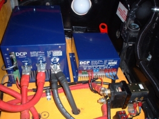
Controller & Converter in trunk of car
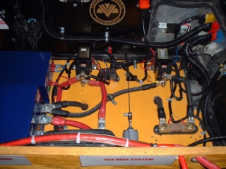
Layout of rear trunk
# (4 of 7) – Block Diagrams and Parts List for; Tilley Building Power System & Tilley Electric Vehicles, by Jerry Decker, for KeelyNet http://www.keelynet.com/tilley/tillblock.htm
Proposed Block Diagram for Tilley Building Power System
The following diagrams are purely the result of my own imagination and ideas as to how I think the Tilley claims could work. They are purely speculation and probably have errors I missed or dreamed up. Your comments and opinions can be sent to the email address above. Thanks!
John Bedini thinks it is one of his gravity fed motors where the secret was released in 1984 and which, like the Tilley motor simply required a drive motor to produce the excess power.
I respect John’s opinion and he might well be right, but before he came forward with this, I was thinking about Carl and some things he told us.
No doubt some were misdirection and because it is a business, I can understand why Carl and his associates would do this. It was quite an amazing thing to be allowed the open access they freely gave us, which to my view, gives them a certain degree of credibility as to the CERTAINTY that what they had isn’t a scam. But only time will tell with this.
It seems to me that our questions indicated Carl knew nothing about Tesla or any other researchers working with electrical generators. Instead, I got the impression based on his description that he had designed and installed off-the-shelf wind and solar power systems when he said he kept ‘running out of daylight’ to keep the solar cells generating. That is when he got the idea for the spinner.
It strikes me that he would have kept abreast of anything new that would be of use in his business including generators. I have long been fascinated by neodymium and rare earth magnets because of their incredible strength in such a small package so decided to see if I could find anything that he might have stumbled on and tested successfully.
Using that as my query, I looked for anything unique or novel about a neodymium based generator and found just such a thing at hydrogenappliances.com where something called a MANTA generator was claimed to produce 12VDC @ 35amps with just one turn of the shaft by hand. Now 12V X 35A = 420Watts. Granted its only a burst of energy but if attached to a drive such as a motor, it just might put out more than what it took to run it by using super strong neodymium magnets.
I posted this to the KeelyNet Interact discussion list and received not one single response saying I was full of baloney. Usually someone would tear into something like this and at least correct my erroneous thinking.
The closest thing was the observation that the torque necessary to spin the generator UNDER LOAD would be significantly higher than WITHOUT A LOAD. I didn’t bring that up in the original post because so many have had the chance to play with the old Army field telephone generators, where the handle spins freely with no load but is very hard to turn with a load applied. But it is a valid point that must be stated.
However, with a generator such as the MANTA connected to a charge controller that fed a battery network, I think the load might require less torque than we think, thus allowing excess energy to be produced and fed into the batteries.
The purpose of this page is to provide simplified block diagrams of both the Tilley Building Power System and the Tilley Electric Vehicle. This in no way is making the claim that it is correct, just information correlated and gleaned from my notes and the many on the net who have shared their observations. Both systems appear to use off the shelf components for the ENTIRE system except for whatever is in the mystery spinner box.
Here is my block diagram of the Tilley Building Supply System based on the photos, video and information I have gathered to date;
The simple logic of it as I can determine;
– 1) – Parallel 8 battery network provides 12VDC to the inverter for 120VAC output
– 2) – 120VAC feeds the DC motor controller from Grainger
– 3) – DC from motor controller adjusts speed of spinner
– 4) – spinner output feeds the charge/load controller
– 5) – charge/load controller adjusts power in to recharge the battery network
– 6) – battery network is kept ‘topped off’ to optimum 12VDC or so by controller
– 7) – inverter provides additional AC through breakers for other building loads
The TRACE charge/load controller is a C-40 model with digital display, rated as charging/load current at 40 amps DC and costs about $160 with meter.
I did get a closeup of the TRACE 2.5kw inverter which I first posted as 25kw based on what Carl said, until I was corrected by Craig Paterson of Australia.
The spinner is of course the key to the entire thing with the output as claimed by Carl to be three times more out than what it takes to run the motor (a COP of 3 – coefficient of performance used to rate efficiency).
Other pages in this seven part series suggest possibilities as to what the spinner might be. I have not included some of the more outrageous suggestions, including electrostatics, scalars, etc.. Unfortunately, the visit to the workshop was completely unplanned so we didn’t get to measure or test anything, not wanting to strain our special invitation out of all the folks who attended the demonstration.
Parts list for the building power system as far as I can make out;
# A – 2.5kw Inverter (converts 12VDC to 120VAC for building power), Model U2512SB RV/Marine Series – $1495.00
# B – TRACE brand C-40 Charge/Load Controller (40 amps) – $160.00
# C – GRAINGER 1F800 – DC controller/motor that drives spinner, 1/2hp / 1725RPM / 56C / 115 input volts / 90 volts / 5.40 amps – $497.25 ; HP @ 1725 RPM = 0.500 – Max Torque @ all speeds (inch-pounds) 16.2 from http://www.grainger.com/
# D – same Charge/Load Controller as B above but disconnected
# E – Spinner with COP 3 – proprietary device inside shielded box ; Tilley claims spinner is $25 WalMart item which is then ‘modified’
# F – Grainger motor as part of controller/motor item C above
# G – 1000 Amp/DC Safety Distribution Center – TRACE PC250 , PV Charge Controller
Proposed Block Diagram for the Tilley Electric Vehicle
The following diagram is my idea of how Tilley adapted the building power system to run an electric car. Please note the need to;
1) – control the 144vdc to the 90-144vdc motor
2) – use a DC/DC converter rated at 144vdc to 12vdc for the car electrical system
3) – convert the proposed 12vdc from the spinner through the charge/load controller into a differently rated DC/DC converter for the 12vdc to be changed to 144vdc – this is to recharge the 12 battery Series network
(12 batteries X 12vdc = 144vdc)
The logic flow for the electric car system to me is;
# 1 – 144vdc from the series battery bus is fed to the motor using a DCP motor controller
# 2 – 144vdc from the series battery bus is fed to a DC/DC controller to produce the 12vdc needed to run the vehicle electric system, such as lights, etc.
# 3 – 1/2 of the 90vdc dual shaft motor drives the vehicle transmission for propulsion
# 4 – the other 1/2 of the dual shaft motor runs the spinner which like the building power system probably puts out something like the COP 3 (three times more out than in)
# 5 – the spinner power feeds into a TRACE charge/load controller which provides stable DC
# 6 – the 12vdc from the charge/load controller feeds a DC/DC converter which converts it up to 144vdc which is added back to the battery bus to recharge the battery network
A parts description list follows;
– A – twelve 12vdc WalMart FLEET batteries in series for 144vdc ; Model 31-5T / Cranking Amps – 1190 / Cold Cranking Amps – 1000
– B – DC Motor controller which is the Raptor 600 model as posted at; http://www.dcpowersystems.com/r600fly.htm ; Input Voltage Range: 48 – 156 VDC Nominal (40 – 180 VDC MAX) ; Output Current (Battery): 600A max, 300A sustained @ 40C, derate 40A per 10C rise above 40C; Freewheel current (Motor): 900A max, 350A sustained @ 40C ; Switching Frequency: 18Khz ; Rev Limit: 4000, 4500, 5500, 6500 RPM ; Shift Blanking Input: 50 or 100mS one-shot PWM dropout ; Contactor control: Switches 4A rated 12V coil. Uses vehicle 12V ; Operating temperature: -20C ~ +75C ; Weight: 18 lb. ; Dimensions: 6.75 x 9 x 12 (HxWxL”) ; Throttle Sensor, Remote Display and Tach Sensor Included ; $1595 + Tax & Shipping Made In USA
– C – 100HP / 90vdc dual shaft motor
Large Motor #FB1-4001; Cost – $1,623.00 / Shipping – $95.00
Length15.70″; Diameter 9.1″; Weight 143.0 lbs.; Input Voltage 96-144 V; Efficiency 90.0%;
Test Data @ 144 V Input :
Time On 5 min. ;Volts 134.0 ; Amps 320 ; RPM 4200 ; HP 48.80 ; KW 36.80
Time On 1 hr. ; Volts 138.0 ; Amps 185 ; RPM 5700 ; HP 30.40 ; KW 22.90
Time On Continuous ; Volts 139.0 ; Amps 170 ; RPM 6000 ; HP 28.50 ; KW 21.50
Peak Horsepower 100.00; Price list page with meters, gauges, motors, mounts, etc.;Electric Auto Website http://www.electroauto.com/catalog/price-pts.shtml
– D – probably use extant car transmission, only requires a motor coupling
– E – Tilleys spinner device with COP 3, might be slightly different from building power supply spinner
– F – probably TRACE C-40 charge/load controller though could be larger due to more batteries, maybe a C-60
– G – probably a DCP brand DC/DC converter for 12vdc changed to 144vdc
– H – definitely a DCP brand DC/DC converter for 144vdc changed to 12vdc
– I – 12vdc bus for automotive electrical system
I think the system to try to duplicate would be the building power system but using a more reasonable sized inverter scheme.
In fact, because I am a big fan of ‘distributed sources’ such as ‘perpetual batteries’, I would rather use an inverter for each breaker, roughly 20amps at 120vac which comes to 2400Watts. Not only are they cheaper but more widely available and efficient to replace should they fail.
Remember CONSOLES and how you used to have basically one built-in amplifier which simply accepted input from various console peripherals (TV, FM tuner, CD player, etc.) so if the amp goes out, because everything is built into one big cabinet, you lose use of it all until you get that amp fixed. As opposed to modern modular systems where you can swap out just the amplifier.
In this case, I’d rather replace one inverter at a time that fed just one breaker than some monster $15,000 to $20,000 unit!!
So, for a home power system or at least one we can test, I think we would need;
-#1 – $1200.00 – a special generator as detailed on page 7 of this series and what I think is the ‘secret’ of the Spinner
# 2 – $500.00 – a DC controller/motor as from Grainger
# 3 – $650.00 – a bank of 8 batteries
# 4 – $180.00 – a charge/load controller
# 5 – $900.00 – approximate total for two 2400 watt inverters
That comes to $3430.00 which I would round out to $5000.00 to actually buy the equipment, cover extraneous costs and run the test with various loads to see if the thing really does keep the batteries recharged without running down.
# (5 of 7) – Bedini Gravity Field Generator, by Jerry Decker, for KeelyNet http://www.keelynet.com/tilley/tillBGFG.htm
John Bedini thinks the ‘secret’ to the Tilley Spinner is that it contains one of Bedinis’ Gravity Field Generators which he freely released way back in 1984 and which, like the Tilley generator, simply required a drive motor to produce the excess power.
I respect John’s opinion and he might well be right, but before he came forward with this, I was thinking about Carl and some things he told us. No doubt some were misdirection, but it struck me that our questions indicated he knew nothing about Tesla or any other researchers working with electrical generators.
The press release back in 1984 http://www.keelynet.com/bedmot/bedpress.htm said witnesses reported that the Bedini ‘Gravity Field Generator’ produced 800% efficiency under full load. Of course, the question arises, if thats true why doesn’t almost every home in the world have them in use. I don’t know.
I do know that John reports many people don’t build the machines as his plans state. Those plans used to be posted but might still be archived at the Wayback Machine site http://www.archive.org/index.html . That the machines fail because the builders would ‘change’ the plans to some idea of their own, then complain when it didn’t work.
Another file compiled from emails http://www.keelynet.com/bedmot/bedtil2.htm sent by John is online if you wish to check it out. I would ask that you notice the heavy flywheel (mass) in the design below as it leads up to page 6 of this series. It appears the use of such a heavy rotating mass is a key to extracting extra energy from gravity, thus the name ‘Gravity Field Generator.’
In our questioning and discussions with Carl Tilley about his discovery, I got the impression based on Tilleys’ description that prior to all this, he had assembled and installed off-the-shelf wind and solar power systems when he said he kept ‘running out of daylight’ to keep the solar cells generating. That is when he got the idea for the spinner.
It strikes me that he would have kept abreast of anything new that would be of use in his business including generators. I have long been fascinated by neodymium and rare earth magnets because of their incredible strength in such a small package.
So I decided to see if I could find anything that Tilley might have figured out or serendipitously discovered and went on to test successfully. But I’m getting ahead of myself, that information is on page 7 of this series.
# (6 of 7) – The Wilson Machine, by Jerry Decker, for KeelyNet http://www.keelynet.com/tilley/tillwilson.htm
In mulling over the Tilley claims over the past few months, what we saw, what my pictures show and what I’ve read on the web, I remembered something that happened in Texas several years ago that I think relates to both Tilley and Bedinis’ Gravity Field Generator.
A friend called me to say I should check out the local paper for an article about an old fellow named Wilson who lives somewhere out in East Texas…I got the paper and was intrigued by the short story because Mr. Wilson claimed to have a big flywheel some 5 feet in diameter and about 2 inches thick. This thing was powered by a DC motor and also ran 2 or more generators which charged a battery network and he claimed this system was self-running…
Well, that got my interest so I tracked down his number and called him…he very kindly invited me out to see his setup….I was working nights but managed to take off for a weekend and drove roughly 150 miles way out in the boonies until I found his house.
When Mr. Wilson was still working (he was I think around 80 years old at that time), he used to run a greenhouse and farmed so he still had some big buildings on his country property….his wife was a sweet little lady who offered us cold lemonade as it was a hot day…
Mr. Wilson took me to a prefab building roughly 20 X 40 with a middle aged black fellow who worked for him as handyman around the house….they had known each other a long time and were pretty close….he said it really did run by itself as he’d seen it tested and had helped Mr. Wilson build it and maintain it.
The machine had a big wooden flywheel made out of a wooden tabletop like you can buy at Home Depot. This flywheel was about 5 feet in diameter and 2 inches thick. He had nails driven all around the rim to form Vees like a V-Belt pulley…this was to hold the long belt onto the flywheel.
He had 2 generators with a tensioning roller for the belt and I think it was a DC motor that drove it. All this was connected by a long belt held onto the wooden flywheel by the nails forming a V all around the rim. The output from the generators was fed to the batteries, the batteries provided power to the motor and he had a small bank of light bulbs hooked up to it as a load.
He cranked it up and it spun, very wobbly and unstable as it was definitely redneck construction…but charming in its way…Mr. Wilson said after running for long periods or if the speed got too high, the nails would come ‘a-flying’ out and cause him to shutdown the wheel…
I asked him the longest he’d ever run it non-stop and he said for 3 days but the nails started a-flying and he had to shut it down….
I stayed there all day, just delighted to hear him talk and show me the various parts of the machine…he used several clip on ammeter gauges at various parts to show the current flowing. He had several of these gauges placed on various wires from the battery to the motor, from the generators, from the batteries to the load, etc. and there did seem to be more current flowing into the batteries from the generator than the DC motor was using to spin the wooden flywheel, unfortunately I don’t recall the numbers as it was some 10-12 years ago.
I asked Mr. Wilson what he intended to do with this, was it for sale, did he want to patent and/or license it, did he want to give it away?? He said he just wanted to help the world, it was not patented nor had anyone else independently proven it.
At the end of the day, I had to drive back to Dallas so he said he was going to tell me the secret. Mr. Wilson said modern generators/alternators would not work in such a system.
He said the flywheel helped to store ‘extra’ energy and that in modern alternators they used excited windings, meaning you have to use current from the batteries to create the magnetic field that is cut to produce current to run the car and recharge the batteries….he said because of this, it could NEVER produce more out than in because it was wasting current keeping the excited windings alive…
Mr. Wilson said only generators from vehicles 1964 and BEFORE had PM (permanent magnets) in them so that simply spinning them produced power….he said he had put in more than 2 generators and generated even more power so that his machine could be scaled up as necessary for greater power production, in other words, it was ‘scaleable’.
The bulbs I saw were fed from an inverter connected to the batteries, there were ONLY 2 BATTERIES in parallel in this arrangement as I recall.
Accordingly, Mr. Wilsons machine seems quite similar to Bedinis’ though on a larger, redneck scale. Mr. Wilson said it is the PM magnet generators that do the trick. His generators were taken from old cars in an auto junkyard and unmodified as was the motor. Everything off the shelf, no tricks, no pulses, no back emf, just that old wobbly flywheel with the nails for the V-belt.
Mr. Wilson might still be alive today, its been about 10-12 years ago when I went to visit him….very nice fellow as was his wife….typical of native Texans, friendly, outgoing, would give you the shirt off their back if you needed it….a pleasure and an honor to have had the privilege to meet him for that one day…
An email sent in on this subject by Emmett says, “The pre 64 “alternators were called generators and even though they contain no permanent magnets, they do not require the field to be excited by voltage, they only need to be polarized in order to get them to charge the right way I.E. plus to minus can go either way.
In my experience, I have found most alternative energy researchers can’t help but try to improve on things, a definite NO-NO with overunity devices where the original MUST be left untampered with. It is safer and smarter to try building another one and see if the effect can be duplicated, but NEVER mess with the original.
I understand this is one of the problems with the Lutec 1000 claim of a self-running magnetic generator. The duplicate generator ‘only works when they used parts from the original.’ A ‘lab-queen’ by any other name.
I thought it would be interesting to apply some of Tilleys off the shelf units to the Wilson system to make a ‘Tilley-fied version’ and this is the block diagram.
To get an idea of how long a 12vdc battery will supply a load, we can use;Ampere load X Duration time = Ampere Hours
A battery that would deliver 2 Amperes for 20 hours would have a 40-amp hour battery rating (2 amps X 20 hours = 40 amp hours).
Another example, a 100 amp hour battery with a 20 hour discharge rate is designed to deliver 5 amps. Every hour it will deliver 5 amp hours and in 20 hours it will have delivered 100 amp hours (if it could be completely drained).
If the battery is discharged faster, its capacity will be LESS and if it is discharged slower, its capacity will be GREATER.
If this same 100 amp hour battery was discharged at 20 amps instead of 5 amps, its capacity would drop to only 60 amp hours. So, at a 5 hour discharge rate, our 100 amp hour battery becomes a 60 amp hour battery.
A 100 amp battery will supply 5 amps for 20 hours, but will NOT supply 10 amps for 10 hours, a kind of discharge reciprocity effect (called the Peukert Effect) based on how fast you pull current from the battery.
A 60 Watt light bulb on a 12 volt system draws about 5 amps (12vdc X 5 amps = 60 Watts).
Another example, if you had a 60 watt load you ran for 10 hours each day for 3 days you would consume 1800 watt-hours (10 hours/day X 60 watts X 3 days = 1800 watt-hours).
Since voltage X amperage = watts, then 1800 watt-hours / 12 volts = 150 amp-hours, the rating for the battery you need.
If you take five 6 volt 10AH batteries and connect the batteries in SERIES, you would end up with a battery ARRAY that is 30 volts and 10AH.
If you connect the batteries in parallel, you would end up with a battery array that is 6 volts and 50AH.
Ordinary auto batteries are made by connecting batteries in series. Six 2 volt cells are put in series to give a 12vdc battery and the 6 cells are just enclosed in one case.
# The Wilson machine used two 12vdc auto batteries in parallel, but I have no idea of their amp-hour ratings. To estimate, lets try 200 amp-hours per battery.
Using the Parallel connection guide above, two 12vdc batteries would yield 12vdc at 400 amp-hours.
That means if we hooked up ten 100 Watt light bulbs as our load, each bulb using 1 amp at 100 volts = 100 Watts, then it would pull 1,000 Watts or 10 amps per hour.
So a dual battery parallel setup rated at 400 amp-hours would last about 40 hours (10 amps X 40 hours = 400 amp-hours), before discharging.
Remember, Mr. Wilson said it ran for 3 days which is 72 hours, meaning if his story is true and it ran the full 3 days, he almost doubled the 40 hour normal run-time.
# I want to point out the use of a heavy rotating mass (flywheel) as used in both the Bedini and Wilson machines, both of which claimed overunity, Bedini on the order of an efficiency rating of 800%.
There could be a connection here between inertial damping/acceleration (as with uni-directional drives that ‘jerk’ themselves in a preferred direction) and coupling with gravity to extract additional energy from the ambient gravity field.
This would lead us to an additional piece of information about what is in Tilley’s spinner box which will be brought up in the next and WHEW!, the LAST page in this series.
# We can also apply this information to the Tilley systems, both building and electric vehicle.
We made no actual measurements but the batteries in the car were the same as in the building power supply except that they used twelve 12vdc Series batteries in the car whereas the building system used 8 parallel batteries.
WalMart off-the-shelf FLEET brand, Model 31-5T, with cranking amps 1190 and cold cranking amps of 1000.
The closest to a conversion formula for cold cranking amps vs amp-hours is;
AMP-HOUR battery rating : calculated by multiplying the current (in amperes) by time (in hours) that the current is drawn.
To determine Cold Cranking Amps (CCA) from Amp-Hour rating, multiply the Amp-Hour rating by 6.
COLD CRANKING amperage battery rating : CCA is the discharge load in amps which a battery can sustain at 0 degrees F. and not fall below 1.2 volts per cell (7.2v on a 12v battery). This rating measures a burst of energy that a car needs to start on a cold morning.
To determine Amp-Hour rating from Cold Cranking Amps (CCA), divide cold cranking amps by 6.
Therefore, the Fleet battery rated with a CCA of 1000 amps, would be 1000 amps / 6 = 167 amp-hours per battery.
For the Tilley Building Power System;
The meter showed 18 amps at 13 volts which is 234 watts.
8 batteries at 167 amp-hours each would be 12vdc at 1336 amp-hours.
1336 amp-hours / 18 amps = 74.2 hours before the batteries should run down, a bit over 3 days.
For the Tilley Electric Vehicle system;
12 batteries at 167 amp-hours each and in SERIES is 144vdc at 167 amp-hours or 144vdc X 167 amps = 24,048 watts maximum.
The FB1-4000 – 85hp peak motor uses 90-144vdc at 190 amps continuous.
Worse case full throttle is 144vdc X 190 amps = 27,360 watts.
Since one HP = 760 Watts, then 85HP X 760Watts = 64,600 Watts.
As you can see it doesn’t add up unless the true battery amp-hour rating is 449 amp-hours, where 64,600watts / 144vdc = 449 amps
64,600W – 24,048W = 40,552 watts more than what the system can produce.
Charge/discharge rates play a part and he won’t be running his electric vehicles for sustained periods at full throttle.
After all it is to my view a much more DYNAMIC system, being in motion, than the building power supply system.
Lots of room for errors in calculation here and I’m open to correction.
# (7 of 7) – The Manta Generator, by Jerry Decker, for KeelyNet http://www.keelynet.com/tilley/tillmanta.htm
As mentioned on the other Tilley pages at KeelyNet, I got the impression based on Mr. Tilleys’ description that he had designed and installed off-the-shelf wind and solar power systems when he said he kept ‘running out of daylight’ to keep the solar cells generating. That is when I think he got the idea for the spinner.
It strikes me that he would have kept abreast of anything new that would be of use in his business including generators. I have long been fascinated by neodymium and rare earth magnets because of their incredible strength in such a small package so decided to see if I could find anything that he might have found out and tested successfully.
Using that as my query, I looked for anything unique or novel about a neodymium based generator and found just such a thing at;
It was called a MANTA generator and was claimed to produce 12VDC @ 35amps with just one turn of the shaft by hand.
#PMG226 – $1195.95 plus $45.00 S&H; weight 22lbs / 8″ X 9″ X 9″ – keyed shaft is 7/8″ by 2.75″ long
I posted this to the KeelyNet Interact discussion list
Usually someone would tear into something like this and at least correct my erroneous thinking.
The closest thing was the observation that the torque necessary to spin the generator UNDER LOAD would be significantly higher than WITHOUT A LOAD. I didn’t bring that up in the original post because so many have had the chance to play with the old Army field telephone generators, where the handle spins freely with no load but is very hard to turn with a load applied. But it is a valid point that must be stated.
However, with a generator such as the MANTA connected to a charge controller that fed a battery network, I think the load might require less torque than we think, thus allowing excess energy to be produced and fed into the batteries.
Now, if you take into consideration the John Bedini and Wilson claims, where both used a heavy spinning mass, it seems to add the final piece to the Tilley Spinner.
Where a high flux magnetic field is connected by shaft or belt to a heavy flywheel (like the 5 foot wooden one used by Wilson) or the flywheel used by Bedini to take advantage of what Bedini CLEARLY RECOGNIZED early on as a gravity tap, thus the name ‘Gravity Field Generator’.
Sorry John, we are all slow to pick up on just how far ahead you really are, since you FREELY released that in 1984!
For me, the combination of the high density neodymium magnet Manta Generator AND a heavy flywheel (which I think and Bedini points out is probably the modification Tilley speaks of), that would fit the bill for the spinner.
At the workshop, I and others put our hands on the thick sealed aluminum box and I could feel no vibration though it was spinning. Meaning the flywheel was well balanced. This box and the DC motor were mounted on a very rigid, metal plate and with thick black rubber sheeting as vibration insulation. I think this was to suppress resonances due to vibration.
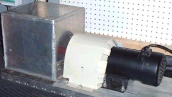
I call your attention to the photo above, showing the thick rubber mat as well as the heavy metal support plate on which the motor and spinner are mounted. To further ‘confuse’ the issue, one of the Tilley asociates told us without that rubber ‘insulation’ the spinner would not work properly, but I think that is simple misdirection.
This isn’t necessarily the answer, just my opinion based on the information provided in this series. I would ask that you take another look at this diagram kindly provided by John Bedini, where he uses a rotating mass (for gravity coupling and energy extracton) and note how the magnet ‘energizer’ is pulsed in a way similar to the E.V. Gray motor but without the ‘power tube’.
… The question always arises IF this thing works, where would the excess energy come from? I tend to think Bedini is right on target, that it does come from gravity in conjunction with bucking magnetic fields.
Such an aether/zpe coupling effect is described by Harold Aspden in post; http://escribe.com/science/keelynet/m13150.html
an excerpt of the key portions;
Imagine an electric machine having no electrical input itself and which, when started on no load by a drive motor and brought up to speed (3250 rpm), thereafter runs steadily at that speed with the motor drawing a little extra input power with a time delay rate of about two minutes.
The machine rotor has a mass of 800 gm and at that speed its kinetic energy together with that of the drive motor is no more than 15 joules, contrasting with the excess energy of 300 joules needed to satisfy the anomalous power surge [to spin up from rest].
Imagine further that when the motor, after running five minutes or more, is switched off and the machine is stopped, you can restart it in the same or opposite direction and find that it now has a memory in the sense that it will not now ask for that 300 joules of excess input. 30 joules will suffice provided that the time lapse between starting and restarting is no more than a minute or so.
This is not a transient heating phenomenon. At all times the bearing housings feel cool and any heating in the drive motor would imply an increase of resistance and a build-up of power to a higher steady state condition.
The experimental evidence is that there is something spinning of an ethereal nature coextensive with the machine rotor. That ‘something’ has an effective mass density 20 times that of the rotor, but it is something that can spin independently and take several minutes to decay, whereas the motor comes to rest in a few seconds.
Two machines of different rotor size and composition reveal the phenomenon and tests indicate variations with time of day and compass orientation of the spin axis. One machine, the one incorporating weaker magnets, showed evidence of gaining strength magnetically, as the test were repeated over several days.
I will soon be reporting in detail on these findings, after further work and evaluation of the implications. The phenomenon was something I should have been prepared for, having regard to my years of theorizing, but this discovery was unexpected as it has crept in loud and clear in a project aimed at testing a motor principle totally unrelated to ‘vacuum spin’. It has appeared obtrusively and I do not yet know whether, in adapting to its presence, it can serve in improving machine performance or become detrimental.
Additional files relating to this aether/zpe coupling effect;
– Reynolds Dilatant Matrix http://www.keelynet.com/osborn/rey4.htm
– Reynolds Bridge between Classical & Modern Physics http://www.keelynet.com/osborn/rey5.htm
– Reynolds Structure for Time, Energy, Space & Matter http://www.keelynet.com/osborn/rey6.htm
– Chaos Conversion http://www.keelynet.com/zpe/chaos.htm
And Finally!
Deckers’ – Bedini/Wilson/Tilley Building Power System Hybrid
I am inclined to think Aspdens sudden starts and stops as with Bedinis’ must also play a part. This also reminds me of the Dean drive, which also used sudden starts and stops to initiate a unidirectional force, essentially rectifying inertia.
A sort of ‘bucking’ effect which could well produce an excess of energy above and beyond what it took to produce the ‘bucking’ as posted in this excerpt from; http://www.keelynet.com/energy/pearson.htm
…with the vacuum underpinned by a compound medium of opposites we can call the ‘ether’, a whole new vista appears. Now energy CAN be created or destroyed – provided negative and positive energies change TOGETHER in EXACTLY balanced amounts!
…At first this seemed to present a difficulty. Would not the two halves of ether MUTUALLY ANNIHILATE as primaries of opposite energy collided at high speed?
…it turned out that the need to conserve momentum prevented MUTUAL annihilation of energies from occurring during collisions. Indeed the two conservation laws of energy AND momentum, which had to be applied SIMULTANEOUSLY, led to a totally different result.
…Instead of annihilating, primaries INCREASED in number! In fact, 18% MORE of BOTH kinds appeared, on average, from EACH collision of opposites.
…When primaries collide by approaching one another from any other direction, so that their trajectories intersect at some ARBITRARY ANGLE, the analysis is only made slightly more complicated. Note it is necessary to consider RELATIVE velocities of approach. From such vantage points some collisions will also APPEAR to be HEAD-ON, so yielding THE SAME RESULT as the one previously described.
…However, for collisions NOT HEAD-ON, a sideway SCATTERING MOTION is imparted. And this applies equally to the general case just mentioned. Each primary GAINS extra momentum in this transverse direction, the positive one gaining positive momentum and the negative one gaining the negative variety. It follows that corresponding evaluation then yields the average gain ratio just quoted (18%).
However, the positive and negative gains of both momentum and energy could CANCEL under conditions of MULTIPLE COLLISIONS (noise). It therefore follows that everything that exists must ultimately have derived from the zero energy state of nothingness.
# Also the late Russian scientist, Chernetskii, claimed that by bucking plasmas together, he could generate an excess of energy.
Another device built, tested and patented by a fellow named Spence from England was a hollow cylinder with anodes on the inside rim and a cathode at the center. Intense magnetic fields swirled around causing a tornadic like focusing of the plasma ions onto the cathode, resulting in claims of overunity.
The Spence device is much like Schaubergers’ ‘impansion/vortex theories’ and the Griggs Hydrosonics device which used ‘shearing’ to produce anomalous/excess heat. All of these indicative of a bucking principle such as the plasma shearing/bucking type effect as with Chernetskii, all part of this aether/zpe coupling phenomena.
There are of course many pieces to these puzzles and claims, even misdirection or lack of clarity in getting the ideas across.
I make NO CLAIMS that any of this is THE ANSWER to the Tilley puzzle but it makes sense to me. Please don’t come whining to me if you spend the bucks to build it and it doesn’t work as I THEORIZED.
In my opinion, it could be built and tested for about $4,000-$5,000USD and welcome anyone who might want to FUND ME to build and test the thing. It doesn’t matter WHO does it, as long as it gets done, verified, duplicated and put into USE or proven as just another ‘crank’ idea that didn’t work when built, won’t be the first time and certainly not the last!
As with all realists, proof comes from buying the parts, assembling it and testing to see if there is an overunity effect.
That is what KeelyNet was designed for and tries to do, bring ‘Order out of Chaos’ by collecting information, sharing it and correlating it as in these pages about the Tilley claims.
Thanks go to Prescott Rathborne for paying for my travel expenses to see the Tilley demo and lab, Dan York for his insights, advice and massive support, Chuck Henderson for his unflagging advice, suggestions and hard work and finally John Bedini who remains a beacon for those of us seeking just ONE working overunity device that anyone can build and USE.
Lest I forget, yet more thanks to the ‘heavenly host’ of folks (KeelyNetters) who share information with me, the discussion list and everyone else who visits or contributes information or donations TO or purchases FROM KeelyNet.
Is this the secret of the mysterious Tilley Spinner?
http://www.keelynet.com/bedmot/bedtil2.htm
Bedini Motor Test #2 – From his 1984 book – Bedini’s Free Energy Generator, kindly shared by John Bedini , KeelyNet – 09/21/02
Is this the secret of the mysterious Tilley Spinner? John Bedini thinks so as he did similar experiments way back in the 1980s as documented in his long available book. The plans were until recently available on Bedini’s website
Date: Sat, 14 Sep 2002 22:23:35 -0700
Let’s get right to it, it is with regret that I was forced by my investors and people who have supported me all along to take down my pages. I have decided to turn my pages into Tom Bearden’s theories and pictures for the simple fact Tom is getting older and it is anybody’s guess what will happen.
I have given to you and your group of ‘chatters’ the most information I could. This brings me to the sad fact that everyone is still searching for something that is staring them right in the face.
I can not seem to get you all to understand that this has nothing to do with “battery desulphation”, I’m not in the business of rebuilding batteries. I’m only in the business of recharging batteries by unknown energies.
It’s a simple fact that to have anything overunity you must have a COP of 1 or better. The Lead Acid Battery fits the bill as it becomes it’s own fuel cell. Now to a better fact, in the 1920 to the 30’s the Tilley device was in use, as his quote said “You do not know your history” and it’s around you everyday and you see it all the time.
Well, he is right, but the device has it’s limitations, I can’t give away his secret because it’s his device, but I do know who the real inventor was and what the machine is. So here Jerry this is what is going to happen.
Let’s drive the car at 30 Mph in high gear and see what happens.
Then let’s go to California and climb to 6500 feet going up a steep pass. It takes about 25 to 30 minutes to climb this, the motor is a DC traction motor – series wound.
(Quote, here is where the motor draws 200 amps, yet recharges at 205 amps, just barely making a Cop of 1)
Anyway now approaching the bottom of the hill, so it’s time to pour on the steam.
The motor is capable of 500 amps at 144 volts providing the batteries have 12 volts in them….72,000 watts of power plain and simple math V x A = W.
I have 25 minutes to go but my car is only doing 30Mph, I hope the converter is as big as the car. My car is doing 22 Mph and I’m not even half way and my batteries are at 10.98 volts and look at the amps, something is getting hot – “OH SHIT!”
I’m doing 10Mph and I can’t coast anywhere. Go with him Jerry see for yourself, Just Kidding! My point here is this car needs a lot of testing which has not been done. To answer your question Jerry, YES, testing was done by not only TUV but also The University of Idaho, and Avista Power and the booklets were printed and given out to the investment group.
I will be posting certain pages on the new sight that I can post. I’m going to be protecting my technology from now on. As far as negative resistors goes it has nothing to do with tunnel diodes or transistors. More on the lines of Kron, Sweet, and others. It is a whole new realm of science, like changing from Tubes to Transistors.
So I wish the best to Tilley and his group for proving that the potential charge technology works, and by the way, back EMF is electrostatic in potential.
# Excerpts from an additional email;Date: Fri, 20 Sep 2002 20:57:23 -0700
…the Magnet static generator is very quiet…(Magneto). Jerry, I printed this book for people to build and not make billions from this invention. The experiment was to show when this thing is rotating it can’t be detected, but Ken is right bring an AM radio and you will hear it. $25 dollars from Wal-Mart to make the switching.
# Date: Fri, 20 Sep 2002 23:56:36 -0700, FREE ENERGY BELONGS TO THE PEOPLE and is not something to make billions!
Take the cover off and prove me wrong let’s see what is on the shaft hidden. I just hate Black boxes. Everybody needs to know how to do this now. He just changed this thing around using a store bought controller. He waited until the technology advanced to come out of the bushes.
Dam good thing I was not there as I would have made the biggest scene you ever have seen. The book is 19 years old, we did not have Good Controllers then, we had to use 555 timers, but the batteries still must be switched.
Look at the size of the box, it would make a pretty good sized Magnet with the magnets we have today.