### Gray, Edwin: his EMA motor
## Rediscovery of the EVGRAY Electric Motor – 02/23/00 http://www.keelynet.com/evgray/evgray.htm
Three Notes:
– This is a sensitive time for the resurgence of the EV Gray electric motor, so for the purposes of safety and anonymity, no names or locations are in this document to protect the principals. This file will be updated or cross linked with additional information as it becomes available.
– Feel free to copy, reprint, mirror or otherwise use these documents or information as you will, the more people who know about it, the better.
– Right click on any photo on this page and select ‘view image’ to see the full picture.
For years, those of us in the alternative science community have heard rumors about the death of Ed Gray. No one has come forward to my knowledge providing any insight into the truth of what actually happened. Recently, a friend and associate was fortunate enough to meet one of the principals involved with EV Gray during his experimental period. We took some initial notes and were graciously allowed to handle and photograph two of the missing EV Gray motors of the six that were built.
…
Our contact was heavily involved with the late EV Gray and has not only the original machined Teflon motor but one of the five prototypes which we were astounded to learn had been built in ARLINGTON (between Dallas and Fort Worth) when EV Gray LIVED IN ARLINGTON for about 3 years from 1986 to 1989! The motors were then scattered across the country after Ed Grays untimely death.
The truth about Ed Gray is that he died in April 1993 in a trailer in Riverside, California where he lived with his girlfriend Dorothy. About 2AM, Ed was home alone when something happened and he was later found dead. The police told her he had a heart attack. Our contact, being a close friend of Ed, was called by Dorothy after the body had been removed by the Riverside police. Although the police said it was a heart attack, our contact noticed a blood stain about 3-5″ in diameter on the carpet where Ed’s body had lain until Dorothy discovered it.
Ed was ‘healthy as a horse’ despite being a big guy, though he did have a smokers hack because he smoked one cigarette after another, but he had no history of heart problems to our contacts knowledge. When our contact asked the policeman why there was a blood stain where Ed had apparently fallen, the policeman said he ‘probably’ struck his head on a counter and blood came from his mouth. When our contact questioned the detective at the police stationhouse, he was told Gray was very paranoid because he had bilked many investors out of large sums of money and so was always afraid someone would come after him. The detective said a drunken woman had mistook Ed’s trailer for her own and it was she who pounded on the door at 2AM which scared Ed so badly that he had a heart attack and died.
Yet a 3rd story given by another policemen was that Ed opened the door at 2AM and this drunk woman shot Ed thinking it was her philandering husband.
Our contact says this is a ‘load of crap’, confirming that Gray was a big burly man with no history of any heart condition, that he chain smoked and had a smokers hack, but nothing else, was strong as a horse and afraid of nothing. Since he died alone, by law there had to be an autopsy, yet when our contact tried to get a copy of that autopsy report as a public record, no record could be found that one had been done. It is possible that one was not ordered, however, on further investigation, our contact says he found no records that an Ed Gray ever lived in Riverside, Van Nuys or in Council, Idaho, all have disappeared.
At one period prior to the actual building of the five production motors from 1986 to 1989, our contact told us that Gray had lived with his sister and her minister husband Reverend Dearing in California, where he was supported by doing work for the church. The story is very fascinating and our contact told us two other principles who were deeply involved with Ed Gray had also died under mysterious circumstances and that it was after Ed’s death when all the mystery started and the motors disappeared. Turns out these two motors were outside a building, subjected to rain and weather, so are not ready for testing. The capacitors used in the capacitor banks have been long ago removed or damaged and are being restored.
Ed’s first wife was Evelyn, mother of sons Mark and Eddie. Our contact was best man at Ed Grays’ wedding with his second wife Star in Council, Idaho. Ed and Star then moved to Arlington, Texas where he built the five production prototypes. The company involved with the patents is EVGray Enterprises, Zetech and Western States. Western is an oil drilling company which owns the rights to the Gray patents. A bizarre claim arose a couple of years ago, where some character was claiming he was a contact for Ed Gray, that Gray had NOT died of a heart attack around midnight at a warehouse in Nevada when he went outside to investigate a noise, according to the rumor we’d heard, but that he had ‘gone underground’ and was glad everyone thought he was dead so he could freely carry on his research. Instead, our contact confirms absolutely that he was one of the pallbearers at Grays funeral in California in April, 1993. He has suspicions who this guy is and that the guy has been promoting Gray’s work as his own for financial scams.
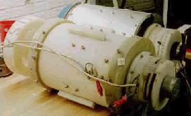
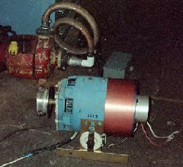
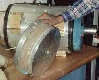
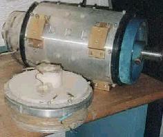
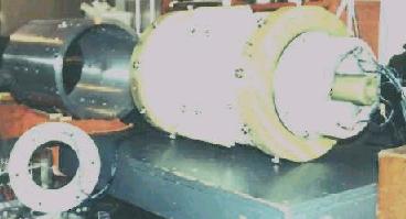
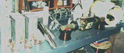
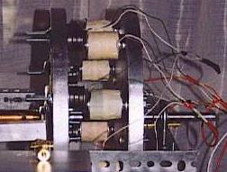
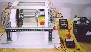
The location of all the 6 existing motors are known as well as one which is mounted in a 6 cylinder automobile with a clutch and transmission which our contact says makes a ‘popping’ sound when it is running. Ed Gray’s original teflon motor has 7 high voltage spark plug cables and one common ground. The teflon motor and one of the production motors is shown on the bench below. The motor under test was fed sequentially by banks of 3 capacitors that were charged up with a high power motor/generator (the blue and copper unit on the floor below), though our contact says in at least one test that he witnessed, they had what appeared to be an overunity demonstration that ran continuously from batteries for 12 hours.
The battery power was measured before the test with the batteries maintaining full charge from the output of the generator and ending up with more power than they had when the test started…ergo; overunity. According to our contact, the FBI and others suppressed anything they could that had to do with the Gray motor since if it was truly overunity and was put into practical use, it would detrimentally impact energy producers all over the world if anyone can make what they need with an overunity device. He also says there is one particular guy who gathered lots of investor money for Gray, with as much as 60 million being placed offshore.
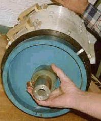
Gray was born around 1930 and worked for NASA as a mechanic where he met Dr. Alexei Popov and they became friends. Popov helped Gray with his idea while Gray worked there and they remained friends after Gray left. Probably the coolest thing we saw was the original demonstration device of a large coil, about 13″ diameter and 2″ wide with carpet on the top. There is an aluminum disc of the same diameter but only about 1/4″ thick with a center coil having a diameter of about 6″ and 2-3″ high.
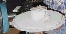
This is supposed to be a larger version of the demo that so amazed Tom Valentine in the article he wrote about Ed Gray. We are told this large version was the one built by Popov so that Gray could demonstrate the basic power of the high voltage coil repulsion. The Tom Valentine story said a magnet was placed on top of a high voltage coil which was connected to a switch, then to a 3,000 vdc photoflash capacitor. The capacitor was charged up then dumped via the switch into the bottom coil which created a high intensity, short duration magnetic pulse that would throw the magnet into the air and hit the ceiling with force. We didn’t get to see a demonstration of this because the 3500 volt DC capacitors haven’t arrived yet, but to check out the motors was definitely interesting as they and this demo coil are a piece of history.
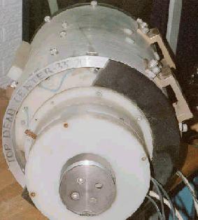
Additional information that was provided courtesy of our main contact prior to release of this document is that the 6 cylinder linear piston motor sounds like a pop corn popper when it is running slow. The design is just like the lawn mower engine design you have posted on the web page. A coil in the top of the cylinder head and a coil on the moving piston. Both get an opposite pulse of high voltage from the capacitor bank. All these motors use an odd number of coils, rotor and stator. The big motor, as shown in the patent, has a three pole rotor and a nine pole stator. The firing of the rotor/stator coils occur every 40 degrees of rotation of the rotor shaft. 9 X 40 degrees = 360 degrees rotation. Since this is a repulsion situation the rotor/stator coils are fired a few degrees out of alignment so as to induce rotation with great torque in the desired direction of rotation. With the capacitor banks arranged in threes, two are in charging mode while one is firing. The spark gaps select the correct stator and rotor pairs to be fired. On the commutator end of the motor you probably remember seeing the timing marks in degrees and a lever that changed the timing and also allowed motor reversal.
Our contact writes that his biggest interest is in the changes that were made between the teflon prototype and the production version. The production version has only three high voltage leads going into the commutation unit with one ground return lead. The other real heavy gauge leads are the back EMF leads used to recharge the batteries. So, looks like its time for the EV Gray mystery to be cleared up and hopefully put into practical use. Our contact said the 6 cylinder motor in the car isn’t running, but its location is known. The plan is to carefully disassemble both motors, the original teflon and one of the 5 production prototypes and compare it to the patent, the blueprints and all the notes that our contacts have accumulated, many directly from Ed Gray.
They want to map it all in detail, then clean it all up and repair what is necessary, then run it and get some measurements – this is just the coolest thing – as I’ve heard for years that the only machine that really had any chance of real overunity was the EV Gray motor but had never seen or heard of anything tangible about Ed Gray until we were kindly given the opportunity to see these machines. It is always highly useful be provided with the initial observation that led to the discovery and scaling up of the phenoemena in question. This is the essence of the ‘Proof of Principle’ document . To build a small high voltage coil with a repulsing magnet as the proof of principle is a great thing to pass on for those who might want to investigate this on their own.
Our host says the production prototype that we viewed on the bench had produced measurements indicating if it was run up to 10,000 rpm, it should produce 1,000 HP. Now that is a quite incredible claim, that a motor this size could produce;
1 horsepower = 760 watts ; so 1000 horsepower = 760,000 watts ; or 760 kilowatts, nearly a million watts!
A house with everything in it running pulls a combined load of about 10,000 to 15,000 watts so that single motor would produce enough energy to run 50 homes at 15,000 watts being drawn continuously, minus of course the energy needed to recharge the batteries that run the motor. Fantasy? It certainly is an incredible claim since there hasn’t even been a device that could produce a sustained 1 WATT of overunity that has been shared publicly so that all can experiment with it. However, this just might be the one, we shall see.
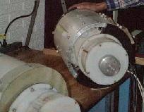
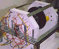
As you can see in the photos the motors are both cylinders about 1.5 feet in diameter and 3-4 feet long, with a pulley on one end. So when they get the capacitors, they’ll be in a position to test them after cleanup and any needed repairs.
Now, let’s be perfectly clear, our hosts are claiming nothing at this time since the motors have only recently been found and so have suffered the ravages of outside storage, however, the hopes are they can be made to run again, in a situation where money and suppressive shenanigans are not the sole driving forces. One of the people involved has IMPECCABLE credentials and trust from several years of contact with many of us, so this is certainly going to be an interesting next few months. Once tests have been done, hopefully we will remain in the loop or they will make their own website which we can link to so that the tests can be shared with everyone.
Our gracious hosts told us the 3500 volt DC capacitors are connected 3 to a bank which are sequentially charged and discharged. The motor has 3 arms on the aluminum machined rotor and there is some kind of 40 degrees spacing to allow coverage of a full 360 degree rotation. I’m not clear on that at this point but the patent is supposed to explain it better. This file will be updated as more information arrives and soon we hope to be able to give full public credit to the folks involved in bringing about and sharing this wonderful re-discovery.
## Inside the EVGRAY Electric Motor – 08/27/00 http://www.keelynet.com/evgray/evgray3.htm
Click on any photo to view full size
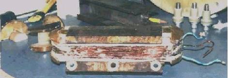
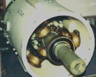
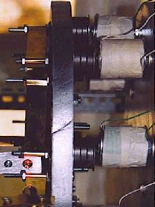
Here are five pictures of the outer cylinder of the EVGRAY motor showing the placement of the inner repulsor coils.
 –
–  –
–  –
–  –
– 
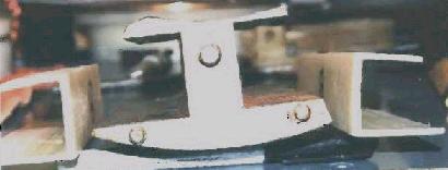
Click on the first one below to see the full image of the very fine laminations used to intensify the field of the custom made high voltage repulsor coils on the rotor.
 –
–  –
–  –
– 
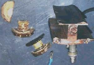
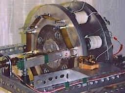
These five show the contactor/distributor plate that functions as a distributor cap to transfer the accumulated high voltage into the repulsor coils to produce high thrust.
 –
–  –
–  –
–  –
– 
Two additional photos showing the blue off the shelf generator that produced power to charge the batteries while the motor ran and the second photo shows disassembled motor components.
 –
– 
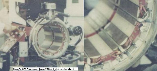
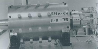
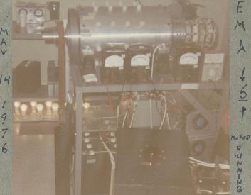
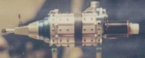
## Exclusive pictures about Gray’s sparking tube and motors EMA, made by G.T. Durnford, in 1974, 75 and 76, form the files of the Yahoo Group : http://tech.groups.yahoo.com/group/alfenergy/
Here some extracts about the EMA motor:
## The Edwin Gray Pulsed Capacitor Discharge Electric Engine http://www.icestuff.com/~energy21/grayphotos.html
Many have thought that the machine had been destroyed by Federal Authorities in bid to stop Edwin Gray in bring to this world this device but parts of the machine have now been discovered on an electronics store junkpile these are the photographs of an researcher who is try to get the Gray machine put together and working again.
if you wish to discover more information on this device please check these following links.
– The Free Energy circuit for the serious researcher http://www.icestuff.com/~energy21/freeenergycircuit.htm
– Edwin Gray’s Energy System by Bruce A. Perreault http://www.icestuff.com/~energy21/edwingray.htm
– Re discovery of the E.V. Gray Electric motor http://www.icestuff.com/~energy21/evgray.html
– The Edwin Gray Pulsed Capacitor Discharge Electric Engine http://www.geocities.com/ResearchTriangle/Lab/1135/gray.htm
– A possible answer to how the Testatika and Edwin Grays machines work http://www.icestuff.com/~energy21/the_answer.htm
– A possible answer to how the Testatika and Edwin Grays machines work alternative brightspark location http://www.icestuff.com/~energy21/the_answer.htm
– Some additional information on the construction Edwin Gray’s conversion tubes http://www.icestuff.com/~energy21/evgraytube.htm
– How Edwin V Grays Conversion tube worked US patent filed 1986 http://www.icestuff.com/~energy21/graypatentjun.htm
# Gray Core and Winding: (Many more large pictures to see on the original page)
# Gray Motor 4 and 5:
# Motor 5, coils:
## Ed Gray impulse coil information http://web.archive.org/web/20040114105827/www.greaterthings.com/News/FreeEnergy/Directory/Inventors/AlanLFrancoeur/GrayMotor/index.html
From: Alan L Francoeur al.f@shaw.ca, sterlingda@greaterthings.com ; Date: Sat Apr 19, 2003 12:13 am
Subject: *****Ed Gray impulse coil information posted on alfenergy*****
Hello Everyone ; Exclusively, you’ve seen this information first on alfenergy. I would like to offer all of you this information to help your progress.
Ed Gray’s radiant energy motor #4 has two impulse coils, one mounted on the rotor and the other mounted inside of the stator housing. The stainless steel shaft is 30 inches long and almost 4″ diameter with large bearings that are priced over $100.00 dollars each. It is obviously built to handle a lot of hp power.
The ROTOR coil mounted in motor #4 has 168 feet of magnet wire gauge #14 wound in it, and the core size is included in the file I uploaded to the archives named, Ed Gray Impulse cores motor #4.
This rotor core has a total of 154 layers of plates that make up the core stack. It also has 3 core sections that are 3/4 ” thick each, one mounted on each end, and the third is mounted in the middle with 77 core leafs on each side of it. The core is a total of 6″ long.
Ed Gray rotor coil has a total of 112 turns of magnet wire wound on it, with 13 layers on the first row, 14 on the second row, 14 on the third row, 15 on the forth row, 14 on the fifth row, 14 on the sixth row, 14 on the seventh row, and 14 on the eighth row.
Ed Gray’s rotor 3/4″ core sections have holes drilled in them with nylon inserts for insulation purposes from the mounting bolts holding the coil to the rotor shaft. The rotor shaft has a counter weight that equals the mass of the working rotor coil, this is to balance the rotor for high rpms.
The STATOR coil has a total of 115 turns of magnet wire wound on it, and this core size is also included in the file I uploaded to the archives named, Ed Gray Impulse cores motor #4. There are 13 layers of #14 gauge magnet wire on the first row, 15 on the second row, 13 on the third row, 15 on the forth row, 14 on the fifth row, 15 on the sixth row, 15 on the seventh row, and 15 on the eighth row. The stator coil has a total of 175 feet of magnet wire wound on it.
There are three solid core sections that are 3/4″ thick each. The one in the middle of the core has 92 layers of core leafs on each side of it, with a 3/4″ solid section mounted on both ends of the cores. Gray stator core 3/4 inch sections have holes drilled and taped for bolt mounting to the inner tube of both of these Gray motors.
The cores in Gray’s coils look to be composed of regular magnetic steel laminates, they can be stamped out of plate material.
There is no amorphous material in Gary’s cores, there for, it is obvious to me that Metglass amorphous materials are not needed to achieve this radiant energy effect..
Ed Grays motor #5 is constructed from very strong nylon and fiber glass grade phanolic materials that are green in color. The shaft is also 30″ long and it is constructed of this green phanolic material, this is a very expensive motor to reproduce. Gray’s constructed his motors with100% high quality precision machine work, and spared no expense in his efforts.
I hope this information helps all you folks out there that are working on radiant energy circuits.
All the best, and have a great day every day. Alan L Francoeur
ALF Aetheric Radiant Energy Research ; Magnetic Energy Systems Penticton, B.C. Canada
Keep on keeping on!
## Technical Discussion: Energy Management Systems http://www.pureenergysystems.com/os/EdGrayMotor/PM_PEM_MG/TechnicalDiscussion/RichardHackenberger/index.html
Report by Richard Hackenberger at the time he was Ed Gray’s Engineer, regarding the EVGray EMA motor and its circuit input-output measurements, scientific basis for the function, and projected development , explaining avalanche power pulse principles in terms of existing models of physics.
Date unknown (1970’s?) ; Also available in original formatting view: Technical Discussion: Energy Management Systems http://www.pureenergysystems.com/os/EdGrayMotor/PM_PEM_MG/TechnicalDiscussion/RichardHackenberger/Hackenberger_Technical_Discussion.tif (865kb tif file)
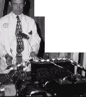
Richard Hackenberger demonstrating magnetic repulsion. (source http://www.free-energy.cc/gray.html )
# Preface
From: [G.M.] ; To: sterlingda@pureenergysystems.c* ; Sent: Friday, May 28, 2004 7:43 AM ; Subject: Proper background for project
[excerpt] Dear Sterling, […] Next week I will send you a copy of a very important document. Edwin Gray’s business was named EVGRAY. Mr. Gray’s electrical engineer was Mr. Richard Hackenberger. Mr. Hackenberger prepared a report entitled “Technical Discussion” in which he
1) disclosed the test results of the EVGRAY motor as tested at UCLA
2) disclosed the exact nature of the operating scientific principles of the motor.
3) Provided important flow block diagrams with critical design values for voltage, current and power.
After reviewing the two patents, the Technical Discussion [this page], and the Summary of Loeb and Meek’s “Mechanism of the Electric Spark”, it should be very clear to you the significance of this information that I am giving you.
Respectfully, [G.M.]
# From: [G.M.] ; To: Sterling D. Allan ; Sent: Thursday, June 03, 2004 7:23 PM ; Subject: ready to go with Eff. Power Supply
[excerpt] Dear Sterling,Wonderful! The ‘Technical Discussion’ contains the essence of Gray’s work that was never disclosed in the patent .
With the recreation of the ‘Efficient Power Supply’ , the “Radiant Event” that Dr. Lindemann refers to in his book appears from the high voltage anode.
Dr. Lindemann and I have gone back and forth on the terminology of the Radiant Event and what exactly is going on in terms of physics. Dr. Lindemann is sometimes put off by my use of standard physics; inverse photoelectric effect, avalanche and quantum theory. He is saying that this is a different form of energy. Dr. Lindemann may very well be absolutely correct. The energy does leave the high voltage anode at right angles to the path of the current, much different than the magnetic flux set up by a normal direct current.
The investigation into the nature of this energy is where the real work begins. With the photos of the power supply and the ER on the power supply the magnitude of the discharge can be observed.
Delivering this “Radiant Energy” to the motor electromagnets is where Gray was able to achieve the results recorded in the test data in the Technical Discussion.
My explanation of the physics of the radiant event that I observed is speculation. The radiant event has been confirmed, the exact nature of this energy is the question. Perhaps your father may be of some help on this one, once the experimental apparatus is set up and the general theory is discussed.
This is real over-unity. — G.M.
# Transcription ; OCR Scan & Transcription by Sterling D. Allan, June 3,4 2004
Page 1; TECHNICAL DISCUSSION ; ENERGY MANAGEMENT SYSTEMS ; GENERAL
For many years the Electro Magnetic Energy Storage System has been used exclusively in the development of kinetic energy from electrical energy. The primary reason for this is dictated by the fact that the magnetic energy that can be stored with a ferro electric field and therefore, the force readily producible by an electro magnet field, is 104th times greater than that conveniently possible with an electro static field.
Losses associated with such systems, due to electrical resistance, gap losses, windage, and other mechanical resistance; are manifested as heat which can not be recovered either as electrical or kinetic energy.
Examination of the purely electro-static forces available, were they readily adaptable for use in practical systems, indicate a superior energy transformation from electrical to kinetic energy would be possible.
In the Energy Management System concept, both the electromagnetic and electrostatic power available is utilized in the conversion from electrical to kinetic energy. This system reduces to an absolute minimum the thermal energy loss. In addition, the Energy Management System offers a means whereby part of the electrical energy involved in producing kinetic energy is being reclaimed electrochemically in all battery operated systems. This design has been Incorporated in the EMS-4 motor by EVGRAY ENTERPRISES INC. With the construction of each of the prototypes, more is learned and design improvements are made.
The latest motor currently under construction will maintain an extremely high efficiency. Such ENERGY MANAGEMENT SYSTEMS will find use in any motive. or stationery power applications.
DESIGN APPROACH
An efficiently designed synchronous A.C. electric motor rated at 10 kw or more, (10 H.P. and above) is 93% to 96% efficient in the conversion of A.C. electrical power into kinetic energy. Such efficiency figures are appealing to the designer of battery operated electric motor devices. However the battery output energy must be inverted to A.C.. The total system efficiency therefore is that of a synchronous motor, less the efficiency of the inverter. Using a standard approach to such a system would result in an overall system efficiency of between 70% and 80%.
A standard well designed brush type D.C. traction motor is capable of this same efficiency, therefore synchronous motors are rarely used in battery operated power systems.
Most A.C. motors currently available operate on 60 Hz (cycles) A.C. line poiwer at voltages from 115 to 230 V.A.C. Special high frequency motors are also available which operate at higher speeds from power converters (changes of 60 cycle A.C. to 1000 cycle A.C.). Such motors where a two pole magnetic system is employed, operate at 60,000 R.P.M. as compared to 3600 R.P.M. for a 60 cycle motor.
Page 2
These high frequency motors use field windings containing fewer turns of wire for a given power rating, than used in 60 cycle motors with the same rating. This is due to the increased reactance (resistance) to alternating current-flow at higher frequencies. Since power turns are used, the D.C. resistance of the high frequency motor fields is substantially reduced. If such a motor could be designed to operate directly from D.C. power an apparent improvement in efficiency is suggested.
If we convert an A.C. motor to a D.C. power source, it will not operate. Only heat is developed. This is due to the lack of commutation (means for developing a rotating magnetic force). In standard D motors, a brush contact commutator is used to cause the motor armature to rotate.
# THE EMS PRINCIPLE
The challenge was to design a highly efficient motor which will operate from D.C. without using a brush contact commutator to achieve an efficiency equal to or in excess of that realized in the A.C. synchronous motor may be obtained.
1. OPERATING .VOLTAGE. Instead of using 115 volts or 230 volts, if we use 2000 or 3000 volts, whatever D.C. resistance the motor field winding may have, becomes negligible. Little or no heat is generated.
2. PULSE OPERATION. Instead of using A.C. or D.C. from the batteries directly we use pulses of D.C. at 2000 to 3000 volts which will further improve the motor efficiency due to (a) use of both electromagnetic and electrostatic energy in the motor field windings. (the electrostatic field strength being increased as well as the electromagnetic field strength in a high voltage system).
(b) Elimination of the brush contact commutator. Pulse operation is provided by a spark gap commutator or a solid state pulse commutator.
The Energy Management System motor (E.M.S.) incorporates these principles in a unique way.
Both the stator (stationary) field windings and rotor (rotating) field windings are low resistance.
During the charge of the magnets, also when the magnetic field is collapsed and if the capacitor bank is overcharged, a 60 – 120 amp D.C. pulse is directed back to the battery pack directly to provide a recycling of the electro chemical energy
# THE E.M.S. MOTOR FUNCTION
In the E.M.S. motor, Evgray Enterprises incorporates the use of high energy narrow pulses of D.C. energy to provide a continuously revolving field due to distribution through a special pulse operated commutating system.
Both the stator fields and the rotor fields are subjected to these cursts [?bursts?] of pulse energy in sequence to cause rotation of the motor shaft.
The motor development introduces a new phenomenon associated with the use of ionized atmosphere wherein chemical dissociation of the atoms and production
Page 3
of avalanche, electronically derived, kinetic energy is combined with the electrostatic and electromagnetic force fields to develop exceptionally high torque with modest power input requirements. In addition, the collapsing electrostatic fields stored in the motor poles produce high current-electrical power pulses which may be utilized to restore electro-chemical power to the battery pack.
# EMA-MOTOR SPECIFICATION (All performance data should be corrected to sea level or test conditions noted)
– Weight – Bare : 300 lbs.
– Weight Including battery and ancillary equipment : 400 lbs.
– Maximum Power. – Continuous : 50-100 HP depend- ing upon battery consumption
– Maximum Torque – Continuous : 240-480 ft. lbs.
– Power/Speed Curve (with and without speed control) : To be determined
– Torque/Speed Curve (with and without speed control) : To be determined
– Efficiency/Power Curve (at constant and varying speed) : To be determined
– Temperatures : 60°C to +150°C
– Humidity : 20% to l00% RH
– Pressure : 10 to 0.2 atmospheres
– Volume : 16″ dia. x 45″ max.
– Battery Current Time Curve : To be determined
– Energy balance summary of the engine : To be determined
– Design Speed : 0 RPM to 5,000
– Acceleration : 0 to 5000 RPM under full load in less than 5 seconds
– Speed variation and stability at constant speed : 2%
– Normal Power : 25H.P.
– Maximum Power : 100 H.P.
– Battery Voltage : 12 Volts
– Battery Capacity : 434 Amp. Hours
Page 4
The EMA motor differs from conventional DC motors in several respects:
1. The batteries do mot directly drive the motor but rather the high voltage generation circuitry.
2. The EMA is a high voltage motor, i.g., 3000 volts.
3. The motor is electro-statically driven which is unique.
4. The motor is response to a high rate of high voltage/low amp power pulse (80-100K/Min).
5. Due to the design architecture the motor has the ability to restore/recycle the electro-chemical energy to the battery pack thereby permitting motor operation over extended periods of time. This will be subsequently explained but it should be noted here that no laws of physics regarding energy are violated.
6. In addition to the recycling noted above, we don’t have the chicken and the egg problem with generators on DC motors. The EMA motor uses a standard 30 amp generator and the energy output is less than the kinetic energy required to drive it.
The EMA motor works by electro-magnetic association. It takes very little energy to activate the EMA motor which in turn produces a great deal of electrical power. This power is harnessed by directing the current flow to electro-magnets which in turn causes a magnetic attraction and repulsion sequence which turns the motor rotor. During motor operation, power from the high voltage section is put through a system of electrical circuitry to produce a series of power pulses. The pulses are transferred to a small control unit, which in turn operates the major motor unit. The control unit, acting in a manner similar to that of a distributor in an internal combustion engine, regulates the pulses, determines their polarity (whether they will be north or south) and directs their power to selected electro-magnets in the main unit.
The shifting position and polarity of the spikes between electromagnets are located on both the rotor and stator of the large motor. Attraction arid repulsion between the two sets of magnets sets the motor/generator in motion. Once in motion, the motor/generator recharges the batteries with 60-120 amp pulses, as a result of the recycle/generation system, and also provides the electrical power required for work to be accomplished. To prevent condensation in the main cylinder and to dissipate a high voltage corona, a 1/2 pound of air pressure has to be maintained. Figure 1 depicts the energy flow in the EMA.
Figure 1: EMS Block Diagram http://www.pureenergysystems.com/os/EdGrayMotor/PM_PEM_MG/TechnicalDiscussion/RichardHackenberger/Fig1_EMS_block_diagram_full.gif
The idea of a recycling electric motor, at first appears to go against much of the theory of electricity and the conservation of energy. The EMA motor/generator does not, however, violate the basic laws of physics, but rather, utilizes them in a unique
Page 5
integration in a system, in order to maximize upon the characteristics and interrelationships between electrical, magnetic, and physical components.
The EVGRAY EMA motor development introduces new phenomena associated with the use of ionized atmosphere wherein chemical disassociation of the atoms and production of avalanche electronically derived kinetic energy is combined with the electrostatic and electromagnetic force fields to develop exceptionally high torque with modest power input requirements. In addition, the collapsing electro-static fields stored in the motor poles produce high current-electrical power pulses which may be utilized to restore electro-chemical power to the battery pack. These pulses are of sufficient magnitude to cause physical damage to standard battery cells. The battery must therefore be extremely rugged to accommodate this synchronous recharge cycle during battery operation.
The development of practical power systems dictates research in the area of battery life. While 90% recapture of the electro-chemical battery power is theoretically possible, it is necessary to limit the recycling of energy to less than 90% to insure adequate battery life.. At the present tire are using a recycling rate of 43%, and the generator provides approximately 25%.
Figure 2 depicts the energy balance and flow measurements in a recent test. EMA-4 Energy Balance and Flow http://www.pureenergysystems.com/os/EdGrayMotor/PM_PEM_MG/TechnicalDiscussion/RichardHackenberger/Fig2_EMA-4EnergyBalance_Flow.gif
To date we have produced 4 operational EMA motors E2 motors incorporating the recycling principle and have validatcd the technical principles involved. EMA-4 has over 1500 operating hours on it. We are presently starting our 5th prototype which is intended to be a 100 BHP automobile engine. Table 1 shows the design specification.
We have planned an 18 month development program (12 months devoted to road, environmental and life tests) for this motor. It will have, a 300 mile range on a continuous run and a 500 mile range on an average driving basis before an external battery recharge is required. We also will be exploring further the following phenomenon:
# Kinetic energy developed in pole repulsion due to ionization of atmosphere in the motor. An ionized gas may carry two conduction currents; one due to the motion of electrons to the positive electrode, and the other due to the motion of positive ions toward the negative electrode. The effect of the positive ions on the forces action between the free electrons is such as to overcome the electronic forces (the space charge) and hence to allow a much greater current of electrons to flow than would occur in a vacuum. In addition, the positive ions attracted toward the negative electrode form an ionic sheath close to the electrode surface and there set up a high electric field which acts in extracting electrons from the electrode, which adds further to the magnitude of the electric current.
Page 6
# Kinetic force of the electro-static field
# Kinetic forces due to chemical dis-association of O2 atoms and CO, O2 recombination again during the force field.
# Whether or not we are consuming any part of the ionized atmosphere as a fuel.
As you may note from the above are attempting to determine exactly why we do get the energy recycling when the motor runs. (In fact at idle speeds, with no load on the motor, you can recharge the batteries completely over a 4 hour period.)
With respect to efficiency we get ridiculous numbers, from an engineering view point, when we relate work output to electro-chemical input, e.g. 173%. We are aware that that is not a real number as it doesnt take into consideration the electrically derived kinetic energy, electrostatic forces, and the electro-magnetic wave front, all of which play a part in the energy recycling. A real number is system efficiency in utilization of the electro-chemical energy which amounts to 99.7%.
Table 2 is an independent engineering evaluation of the EL motor, performed by Crosby Research Institute. Some of the design objectives in the planned automotive motor deve1oent are as follows:
– Component interchangeability without the need to readjust
– Use of standard off-the-shelf components
– Design to achieve multi-sourcing of components
– Use of standard. interchangeable parts
– Use of standard materials and components
– Modular design
– Modular integration
– Modular plug-in components and parts without need to readjust
– Modu1ar system architecture
– Modular integration – basic motors pre-wiring and connections for most common options, input/output controls, and energy storage expansion
– Special attention to:
— Industrial design — Quality Control — Assurance — Maintainability — Documentation
– Use of a standard quality components and materials.
With respect to maintainability and reliability, it is expected that the motors will be maintained by the end-user, therefore, the machine will be designed to reduce servicing cost in conjunction with the following maintenance philosophy:
Page 7
– Simple, efficient, diagnostics incorporated within the system, or by use of relatively inexpensive ancillary test equipment (voltmeters, etc.) by unskilled personnel.
– Repairs will be performed by replacement of the faulty part: by spare parts (which will be repaired in service centers). Estimated mean-time-to-repair (MTTR) for a worst case condition is 30 minutes, with 15 minutes being the average.
I dont mean to burden you with all of our plans, etc., but I thought it best to show that while we have something that is real, there is still a lot of engineering required in order to develop a practical automotive motor that could serve as a rep1acrent for an internal combustion engine and not have the present constraints that existing electric autamotive motors have with respect to battery recharging and vehicle performance. I would judge that from a technology status we are a little bit ahead, engineering wise, than JPL is with their Hydrogen conversion motor. We know that we can produce a practical automotive motor based upon what we’ve learned from our existing prototype, but there are still some uncertainties that have to be resolved before there is a marketable product, i.e. manufacturing costs (design goals are $300), the impact on the vehicle and whether or not any vehicle engineering would be required.
I’m sorry that I dont have more information to give you at this tire bit we do have a proprietary position to protect. We are a public corporation in California with approximately 600 shareholders and have invested better than $800, 000 in engineering and development in the past 3 years. I might note then 2 years ago we did apply for a research grant from the DPA office of Air and Water programs in Michigan but we were turned down for having a polluting motor. (i.e. when the batteries are recharged they cause a drain on the local power company, and generating plants are notorious polluters, therefore we had a polluting motor with our 4 batteries.) The only emission from the motor is the high voltage corona, or ozones. In addition, the motor does extract moisture from the air during operation.
I hope that an of this makes sense, because we do understand the credibility problem, for an outsider when one considers physics principles. From an engineering viewpoint we are assured that we are not violating any physical laws even though we dont. have all of the answers yet. By continuing to use standard engineering methodology we are continuing to learn more each day.
Thank you for your interest in our company. EVGRAY ENTERPRISES, INC. ; BY [RB Hackenberger signature]
Unfinished attempt to replicate, with large modifications, a Gray’s type motor; most interrresting part is the ‘Spark Power Supply’, on the Gray’s Spark Tube page of this website, see menu on top
## Pulsed Electromagnetic Motor by G.M. — Prototype 2 http://www.pureenergysystems.com/os/EdGrayMotor/PM_PEM_MG/prototypes/motor/GM2/index.html
Presently-working device by G.M. is a variation of Ed Gray’s patent 3,890,458. G.M.’s version (variant) uses a combination of permanent magnets and electromagnets.
# From: [G.M.] ; To: Sterling D. Allan ; Sent: Sunday, May 30, 2004 2:45 PM
Subject: Photos of present prototype PM/PEM,MG
Dear Sterling,Here are the photos of the present prototype under construction. PM/PEM,M-G The low voltage power switching using infrared laser is now under construction and run in testing has been performed.
Perfecting the laser switching will take time, but it is worth the effort, no drag or parts to wear out . Mechanical commutation was employed in the first prototype PEM.
— GM
# Motor Working Nicely
From: [G.M.] ; To: Sterling D. Allan ; Sent: Monday, May 31, 2004 8:21 AM
Subject: PM/PEM,M-G Circuits
Dear Sterling,The motor is firing nicely and runs. At present I am employing mechanical pulsing to adjust timing of the attraction and repulsion phases. The circuit testing will consist of four different circuits, two low voltage and two high voltage. The laser switch, consisting of a laser and a photo-detector provide the on-off switching for pulsing the electromagnets.
Continuous run-in testing will take place this week. The circuit consist of a pnp bipolar medium power transistor connected to a npn high current power transistor, in a darlington pair configuration. The laser switch provides the base current to pnp transistor. The laser and photo-detector are operating and performing nicely in testing. The transistor circuit will replace an old pulsed dc circuit I have been using for testing purposes. I will make the schematics of the circuits available when they are properly tested.
The high voltage circuits are dangerous, similar to the Efficient Power Supply Suitable for Inductive Loads. That is where continued experimentation with avalanche takes place. Gray circuit prototype # 1 employed avalanche.
I prefer low voltage circuits because of safety and the potential for mass marketing, although less powerful.
After continuous run in testing I plan to have the results inspected by a licensed electrical engineer and have him stamp the test results to avoid any confusion or misrepresentation. This will be part of the Preliminary Report scheduled for July.
After you receive the ‘Technical Discussion’ by R. Hackenberger I will send the working drawings for the motor. Perhaps your mechanical engineer can review the drawings and build a prototype. It is not expensive, under $500.
[…] GM
## Pulsed Electromagnetic Motor by Gary Magratten — Prototype 3
Presently-working device by Gary Magratten is a variation of Ed Gray’s patent 3,890,458. Gary’s version uses a combination of permanent magnets and electromagnets.
# Explanation
From: [Gary] Magratten; To: Sterling D. Allan; Sent: Wednesday, August 11, 2004 2:43 PM; Subject: PM/PEM2,MG
Dear Sterling,Here are some pictures of PM/PEM2,MG The [engineering] testing was halted because the lateral loading to the bearings was not designed for [such extended running].
The Engineering Report is still on schedule for PES review.This should put us actively back on tract with the open sourcing project.
Sincerely, Mr. Gary Magratten
# From: [Gary] Magratten ; To: Sterling D. Allan; Sent: Wednesday, August 11, 2004 6:12 PM ; Subject: good news!
Dear Sterling,[…] They freed me up to disclose any and all work on PM/PEM2,MG. […]
There are minor design errors that are discussed in the Engineering Report. These will not be difficult to correct.
Essentially the unit needs to be balanced for lateral forces as well as axial forces. More work, but it can be done. I will have to employ back emf from the motor coils to get real over-unity.
[…] I will send the full ER with all working drawings and assembly instructions probably next week for PES review.
Sincerely, Mr. Gary Magratten
# From: Margaret Magratten ; To: Sterling D. Allan ; Sent: Thursday, August 12, 2004 7:49 AM ; Subject: PM/PEM
Dear Sterling, You will receive the ER next week. It details exactly were I am at with this. I got some good numbers but the lateral loading on the bearings needs to be addressed before there is sustainable power production. The bearings started to fail as there is some 800lbs of lateral load due to the neodynium magnets.
The motor consumes 3.5 amps at 12 volts, 42 watts input. This has been tested several times. The alternator is designed to put out 750 watts at 500 rpms.
Because the motor and alternator are one unit, it is difficult to test the the motor and alternator independently. I will split the units. The production of electric power is dependent upon the rpms of the driving unit and may have to use a gear assembly.
I am planning to do a video that clearly defines the present state of R&D. In the video, I hope to outline the design improvements necessary. These improvements are not difficult, and I will provide the design and test results as I proceed. We can post the updates as we progress.
This is still in the R&D stage and not finished product ready for market. I would suggest that you have your Electrical Engineer and Mechanical Engineer review the ER. I will work on a summary of the ER for PES.
The ER is very detailed and will clear up any questions. Respectfully, Gary Magratten
## EV Gray Circuit and Motor are Really Two Separate Projects http://pureenergysystems.com/os/EdGrayMotor/PM_PEM_MG/description/circuit_v_motor/index.html
From: [Gary] Magratten; To: Sterling D. Allan; Sent: Thursday, August 12, 2004 5:20 PM
Dear Sterling,To the Message Group – E.V.Gray Motor specifically k4zep@e and iron1of1.
The Gray Circuit Project is really a completely separate project. The discharge from the circuit left me swimming in the deep end of the pool of theoretical physics. Last night I was reviewing Paramahamsa Tewari’s theoretical work, ” From The Electron To A Perpetual System of Motion”. He touches on electron/ positron annihilation but does not consider the well known fact that an electron and a positron can combine to release pure energy. [ no pun intended PES ].Perhaps we should split the two projects.
The practical reason for not working on H.V. Avalanche is that when I went to see about supplying experimental units for others, the product liability insurance agents refused to even do business.PM/PEM2,MG is exactly what you see. I am pounding away at this because I can see my way through to a practical unit that can make it to market.
Here is how it works in a nut shell:
1) The permanent magnet/ pulsed dc electromagnet motor is powered 1/2 the time by the attraction force of the permanent magnet to the electromagnets core. No electric power consumed. The dc pulse repels the magnet to the next attraction phase.
2) When the pulse ends, the magnetic field of the electromagnet coil collapses. This provides a back emf that can be employed to charge a secondary battery on the motor side. E.V. Gray’s motor patent.
3) The alternator is a new design from Hugh Piggot for wind generators. The trick is that the coils have no individual iron core. That means that the permanent magnet rotor is free to spin with little or no drag. The design has been repeatedly built and tested. See http://www.wondermagnets.com/ http://www.otherpower.com/
Thank you Dan Bartman for making the design work public domain.
I am simply trying to marry my Gray version motor to the alternator. Where I made a mistake was not designing for lateral loads. The bearings couldn’t handle the lateral load of the 16 neodymium block magnets. Dual stators on the motor and the alternator should solve the problem. Coupled with the back emf from pick up coils, this unit should go way over-unity. Thank you Douglas Konzen. Motor consumes 42 watts. The alternator is designed for 750 watts out.
When I complete PM/PEM2,MG I may again try to work with high voltage. Study Loeb and Meek’s work “The Mechanism of the Electric Spark”. I am thrilled that some one is working on the Gray Circuit. If I can answer any questions, I will give it my best shot.
There are a lot of errors in the Gray Circuit ER.George Wiseman of Eagle Research http://www.eagle-research.com/ has two new essays on energy recycling. I have just ordered these and am really anxious to read them. They may be very valuable to PM/PEM2,MG and Gray’s Circuit.
I was going to redesign the Gray Circuit for a second prototype but got involved with PM/PEM2. It is too difficult to work on two R&D projects at the same time. If I don’t answer your questions, it is because I am swamped.
Please keep trying. I make a real effort for those actually physically doing research. Respectfully, Gary
## Five Factors That Make the Gray System Work http://www.pureenergysystems.com/os/EdGrayMotor/PM_PEM_MG/theory/FiveFactors/index.html
From: Gary Magratten ; To: Sterling D. Allan ; Sent: Monday, June 14, 2004 6:26 PM ; Subject: Answers to questions
Dear Sterling, There are 5 major factors that make the Gray Motor Circuit and the Gray Circuit , ‘Efficient Power Supply Suitable for Inductive Loads’ important in motor circuit design work.
1) The ‘Radiant Event’ which is developed from the H.V. steel anode and coupled to the load circuit by the copper collection tubes appears to provide a large increase in energy. I attribute this to the ionization of air molecules in the spark gap. Each bound electron gains a quanta of electromagnetic radiation during the ionization process. As there is a multiplication of free electrons due to avalanche the release of quanta of electromagnetic radiation when the free electrons strike the H.V. anode is proportional to the increase in free electrons. The process by which electrons release EMR on impact to the H.V. anode is refered to as the “Inverse Photoelectric Effect”
2) The increase in ‘free electrons’ due to avalanche is directed back to the primary and secondary batteries. See schematic and trace the circuit path back to the neg. terminal of the batteries.
3) The current in the circuit is recycled back to the negative terminals of the batteries.
4) The power pulse delivered to the electromagnet load is [ in phase] high voltage, high current for the optimum duration at the optimum time.
5) The collapsing EMF of the electromagnets is utilized to recharge the secondary batteries. Not shown in the schematic but stated in the Tech. Discussion and Patents.
As I am very busy with bringing this to market, I will not have time to answer questions from those simply curious. If someone is actually working on the circuit or working on the recreation of the ‘Radiant Event’ , then I will try to make time.
Does the ER on the power supply have errors? Yes, it does. It was my first attempt at the recreation. That is the nature of R&D , trial and error. If someone wants to actually do work and make constructive contributions, that is very welcome. I am sorry that I can not answer all questions for all interested but I simply do not have time.
If there is someone who is knowledgeable in this area of physics who wants to make a contribution, ie.; avalanche, inverse photoelectric effect, ‘Radiant Event’ or ‘positron / electron annihilation’ – P.A.M. Dirac Theory , quantum theory in relation to air molecule ionization and ‘bound state’ to ‘free state’ and back again, then we can talk.
Respectfully, Gary Magratten
## About Gary Magratten (G.M.) http://www.pureenergysystems.com/os/EdGrayMotor/PM_PEM_MG/GM/index.html
Gary says he has been able to replicate Ed Gray’s motor, using permanent magnets — which is his intellectual contribution. He wants to give the technology away. Hence this site, commenced May 26, 2004. He has since (June 1, 2004) signed an NDA with a manufacturing company to bring a related technology to market, so he may be somewhat limited in how much he can help here. He does have several very capable and brilliant friends who are watching the progress here and offering helpful advice. We do not wish to undermine the proprietary advantages of the manufacturing company Gary is working with. We do wish to help propagate the basic general understanding for the benefit of the advance of this technology.
From May 26 through June 4, Gary requested to remain anonymous to avoid an onrush of correspondence. He does not mind his name being known, but would like to pass the correspondence through the project director.
In the future, once the information on this site is adequate to clearly and concisely convey how to replicate this technology successfully, and most key questions are already answered, Gary may post his contact information and biography here. Meanwhile, we ask that you honor his request for solitude while he works on helping a similar technology make it to market (estimate one year).
— Sterling D. Allan, project director ; May 26, 2004; updated June 4, 2004