Energizer, from http://www.rexresearch.com/jamison/jamisn.htm
San Francisco Examiner (Sat., January 3, 1981), p. A6Inventor Juices up a 200,000-Mile Car
Memphis, TN (UPI) — A Mississippi mechanic claims he has invented an electric car that will run 200,000 miles without gasoline, oil, water or even recharging.
Larry Jamison calls the motor the Jamison Energizer. The 65-year old Nettleton, Mississippi man commutes to Memphis seven days a week to labor on his invention, housed in his one-room shop.Two years ago I went to work on the idea full-time, and Ive been working seven days and nights a week ever since, said Jamison.
He says he can wire the dozen or so cylindrical-shaped motors and energizers into virtually any truck or car — at a cost of about $6,000.The difference between this motor and all the other electrical cars on the market is that mine never needs to be recharged, he said. It produces more electricity than it uses and stores it in batteries.
Also, those other cars dont have any real power. Ive got a motor that will outdo your Cadillacs and your Lincolns. When we get into production, Ill guarantee the motor for 200,000 miles. Jamison Thursday displayed a 1977 Ford Courier pickup equipped with a Jamison Energizer. He admits it has a couple of small bugs.He said a control switch that acts as an accelerator is giving him problems and keeps him from driving the pickup himself.
Jamisons secret is a shiny metal cylinder a little mor than a foot long and about 10 inches in diameter. He wont discuss what makes it work.This is the only one like it in the world, he said. I dont care what electrical engineer you bring out here, this is different. Its not in the book.
Jamison said no one will believe his idea will work.For two years, people have been saying, Youre nuts — it wont run. Everybody just said I was throwing my money away — that it wont run a lick, he said.As Jamison talked, an associate drove the pickup back and forth across the shop.Its working, he told the onlookers. You can see that for yourself.
Jamison says hes been contacted by major firms in Germany, France, and the US, but doesnt plan to make a deal.But I aint going to let nobody have it, he said. I want to manufacture it myself.
[ Larry Jamison died in 1987. His business associates were L and J Enterprises, Inc., 1299 McLamore St, Memphis, TN; Tele. 901-942-9313; Bill Tunstill, Gen. Mgr. ]
European Patent Application EP 0 067 755; Energy Source Employing Electrical Energizer http://www.rexresearch.com/jamison/jamsnpat.pdf (PDF, requires Adobe Acrobat Reader)
# Extracts from the patent:
European Patent 0 067 755 A1, Energy Source Employing Electrical Energizer, 22.12.1982, Jamison, Larry T., PO Box Drawer L, Nettleton Mississippi 38858 (US)
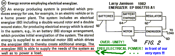
An energy producing system is provided which produces energy for use, for example, in an electric vehicle or in a home power plant. The system includes an electrical energizer (60) including a double wound rotor and a double wound stator, for producing electrical energy which is stored in the system, e.g., in a battery (66) storage arrangement, which provides initial energization of the system. The stored energy is supplied to an electrical motor (68) which drives the energizer (60) to thereby create additional energy. The energizer (60) is able to supply the needs of the system as well as to power a load.
The present invention relates to energy producing systems, more particularly, to an electrical energizer-motor system for providing energy, e.g., for an automotive vehicle or as part of a home energy plant.
With the advent of the so-called ‘energy crisis’ and the consequent search for alternative energy sources as substitute for oil, considerable attention has been focussed on automotive vehicle as chief users of oil products. One aspect of this search has fostered renewed interest in electrically driven vehicles such as electric cars and the like. A principal shortcoming of prior art electrical vehicles has been the need to recharge the batteries which provide the power for the electrical motor drive system.
The present invention overcomes this problem through the provision of electrical energizer-motor system which produces more energy then is expended, thereby enabling the excess energy to be stored in the battery system and to be drawn upon as required. Thus, the need for recharging of the batteries associated with conventional electrical vehicles is eliminated with the system of the invention. It should be noted that while the system of the invention has enormous potential in connection with the use thereof in electrical vehicles, the system clearly is not limited to such use and would obviously be advantageous when used, for example, as the energy source for a home energy plant, as well as in many other applications.
In accordance with the invention, an energy producing system of the type described above is provided which comprises an electrical ‘energizer’ comprising at least one double wound stator and at least double wound, shaft-mounted rotor located within a housing, electrical energy being collected from the rotor through a suitable electrical take-off device and being available for utilization by the system ; and an electrical motor, powered from the energizer, for driving the rotor shaft of the energizer. A battery arrangement is used to initially supply energy to the system and, as stated above, the excess energy generated by the energizer over and above that required by the system, and the system load, is stored through charging of the batteries. The motor includes an armature including a plurality of winding slots therein and a plurality of windings, at least some of the windings being wound into two circumferentially spaced slots in the armature, i.e., such a winding is wound through a first slot (e.g., slot #1) and returned through a second spaced slot (e.g., slot #5). Depending on the energy demands, the energizer may include a pair of stators and rotors, with the rotors being mounted on a common shaft. The motor is preferably energized through an arrangement of a commutator and plural brushes, while a slip-ring and associated brushes connected to an output bridge circuit from the energy take-off means for the energizer.
Other features and advantages of the invention will be set forth in, or apparent from, the detailed description of the preferred embodiments which follows.
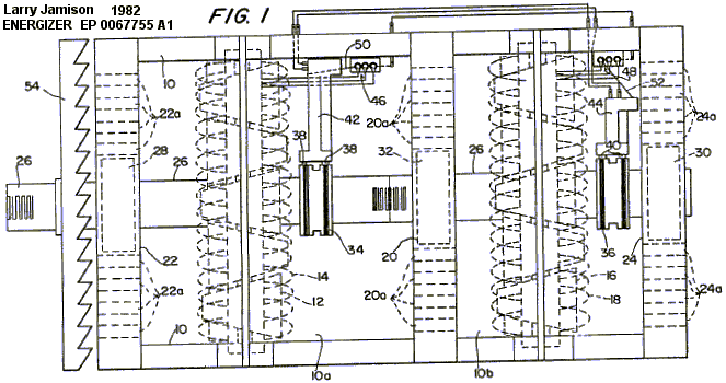
– Figure 1 is a partially sectioned elevational view of the electrical ‘energizer’ of the invention;
– Figure 2 is a block diagram of the overall energy producing system of the invention;
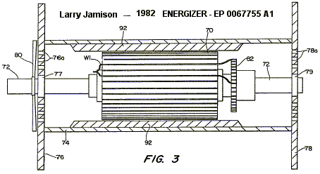
– Figure 3 is a partially sectioned side elevational view of a modified electrical motor constructed in accordance with the invention;
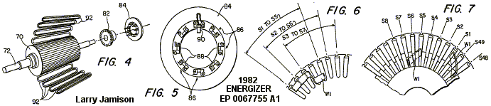
– Figure 4 is an exploded perspective view of the basic components of the motor of Figure 3;
– Figure 5 is an end view of the brush holder also illustrated in Figure 4 ;
– Figure 6 and 7 show details of the winding pattern of the motor of Figure 3.
Referring to Figure 1, a preferred embodiment of the ‘energizer’ device of the invention is shown. The device includes a jousing 10 in which are located, in a first chamber or compartiment 10a, a first rotor 12 and a first stator 14 and, in a second compartment 10b, a second rotor 16 and a second stator 18. It should be noted that although two stator-rotor combinations are employed in this embodiment, a single rotor-stator combination can be used for some applications. Housing 10 is divided into the compartments 10a and 10b by acenter plate 20 and includes a pair of end plates 22 and 24. Both the rotors 12, 16 are nested within respective stators 14, 18 and mounted for rotation on a common shaft 26. Shaft 26 extends longitudinally through housing 10 and is mounted on bearings 28 and 30 supported by end plates 22, 24 and a further bearing 32 supported by central plate 20.
A pair of slip rings 34 and 36 are mounted on shaft 26 and cooperate with respective brush pairs 38 and 40. Slip rings 34 and 36 are connected to rotors 12 and 16, respectively, and permit the current flowing in the rotor windings to be collected through the associated pairs of brushes 38, 40. Brush pairs 38, 40 are mounted on respective brush holders 42 and 44. The terminals of respective bridge circuits 46 and 48 are respectively connected to stator 14 and 18 while conversion bars 50 and 52 are connected to brush holders 42 and 44, as indicated.
A cooling fan 54 is also mounted on shaft 26 and a plurality of apertures 20a, 22a, and 24a are provided in center plate 20 and end plates 22, 24, respectively, to promote cooling of the device.
The energizer of Figure 1 is preferably incorporated in a system such as shown in a highly schematic manner in Figure 2 wherein the output of the energizer is used in supplying the energy for driving a motor. To this end, the energizer, which is denoted 60 in Figure 2, is connected through a regulator 62 to battery charger 64 for batteries 66 connected to a motor 68. These batteries 66 are used to provide initial energization of the systems as well as to store energy produced by the energizer 60. It will be understood that the energizer 60 provides energy enough to power motor 68 (which, in turn, drives energizer 60 through rotation of shaft 26) as well as to provide for storage of energy in the system. It will also be appreciated that the system illustrated schematically in Figure 2 includes suitable controls (switches, rheostats, sensors, etc) to provide initial energization as well as appropriate operational control of the system.
In a preferred embodiment, motor 68 is of the form shown in Figure 3. As illustrated, the motor is of a generally conventional form (with exceptions noted below) and comprises an armature 70 mounted on a shaft 72 within housing 74. Housing 74 includes a pair of end plates 76 and 78 which mount shaft bearing 77 and 79. Apertures 76a and 78a are provided in end plates 76, 78 and a cooling fan 80 is mounted on shaft 72 to provide cooling.
A commutator 82 is also mounted on shaft 72 and cooperates with associated brushes (not shown in Figure 1) to conduct current to the windings of armature 70. This cooperation is shown best in Figure 4 which is an exploded view illustrating the armature 70, commutator 82 and a brush holder 84. As shown in Figure 5, the brush holder 84 includes eight brush mounts 86 each of which defines a slot 88 in which a pair of brushes is mounted. One brush 90 is shown in Figure 5, it being understood that two such brushes are mounted in each slot 88 so that sixteen brushes are required.
The motor of Figures 3 to 6 includes eight pole shoes (not shown) which are secured to housing 74 and which serve to mount eight field coils or windings 92 (see Figures 3 and 4) about the periphery of armature 72 in spaced relationship thereto.
An important feature of the motor of Figures 3 to 6 concerns the manner in which the windings for armature 70 are wound. As illistrated in Figures 3 and Figures 6 and 7, a typical winding WI is wound in two slots, with the illustrated winding being doubled back and continuing from armature slot S1 to armature slot S5 (see Figures 3 and 6). The ends of the winding extend from slots S1 and S5 to the commutator 82, as shown in Figures 3 and 7. Similarly, the winding in slot S2 continues to slot S6, the winding of slot S3 continues to slot S7, and so on for the forty-nine windings.
In a specific preferred embodiment, the motor described above is a 48-volt, 412 horsepower motor having a top operating speed of 7,000 rpm. A rheostat control (not shown) is used to control the input voltage and, as discussed above, the motor is powered from the energizer of Figure 1. It will be appreciated that the energy take-off from the system is preferabely from the output shaft of the motor although electrical energy may also be tapped off from the energizer output.
Although the invention has been described in relation to examplary embodiments thereof, it will be understood by those skilled in the art that variations and modifications can be effected in these examplary embodiment without departing from the scope and spirit of the invention.
CLAIMS:
1 . A energy producing system providing an output for utilization by a utilization device, said system comprising:
an electrical energizing means comprising a housing (10) ; at least one double wound stator (14 or 18) located within said housing ; at least one double wound rotor (12 or 16) located within said housing ; a rotor shaft (26), supported in said housing, on which said double wound rotor is mounted ; and energy take-off means (34 or 36), including means mounted on said shaft and connected to said rotor, for collecting electrical energy from said rotor for withdrawal at least one stationary output ;
motor means (68), including means connected to said electrical energizer means to provide energization of said motor means, for driving said rotor shaft of said energizer, said motor means inlcuding an armature (70) having a plurality of winding slots (S1 to S49) therein and a plurality of windings (W1) wound in said slots, at least some said windings (W1) being wound in two circumferentially spaced slots (S1 and S5) in said armature ; and
energy supply means (66) for supplying electrical energy to said motor means at least during initial energization of said motor means and being connected to said output of energizing means for receiving energy from said energizing means and for supplying said energy to said motor means during the operation of said motor means.
2 . A system as claimed in Claim 1 wherein said energizing maens includes a pair of said rotors (12, 16) and a pair of said stators (14, 18), said rotors being mounted on a common shaft (26).
3 . A system as claimed in Claim 1 wherein said energy take-off means comprises means, including a slip ring (34 or 36) and at least one brush (38 or 40) for collecting electrical current from the windings of said rotor, said brush being connected to a bridge circuit (46 or 48) connected to said output.
4 . A system as claimed in Claim 1 wherein said motor means includes a commutator (82) through which energy is supplied to the windings of said armature.
5 . A system as claimed in Claim 4 wherein the same winding (W1) is wound in the first and fifth slot positions of the armature of said motor and the ends of that winding are connected to two spaced positions located around the periphery of the commutator (see Figure 3).