(page created for November 2007 update)
Future Horizons, Inc. – Po Box 125 Marquette, MI 49855 USA – http://www.futurehorizons.net
Free-energy plans
Simple Circuit to prove free-energy exists. from ‘Free_Energy_Plans.pdf’ or at http://forum.osen.org/Home/tabid/36/forumid/14/postid/473/view/topic/Default.aspx
Also plans to show you how to build a completely solid-state free-energy circuit! Output is over 100% efficient!
This motor consumes no charge
This is a simple experiment using a toy motor to demonstrate the principle that charge is not consumed but wasted in conventional electrical circuits. You could actually use just about any type of load even an LED, but some people will argue that the LED would “consume” too little energy.
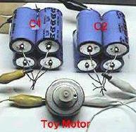
So here is the setup: C1 & C2 each consist of (4) 10,000 uf electrolytic capacitors hooked in parallel adding up to 40,000 uf EACH. C1 is charged with 12.5 volts C2 got 0 volts. The key point of the experiment is to transfer charge from C1 to C2 through the toy motor. After discharge C1 and C2 are left with 6.25 volts EACH. Joules energy calculations rule a 50% energy loss. This incorporates the claim energy was not equal to charge. If you can’t believe that, try it on your own. Theoretically it seems possible to pulse the current of the 6.25 v capacitors through a 1:2 transformer up to 12.5 v. Some people argued that the method of measuring the running time only was not enough since there was no regard to the RPM. I agree on that and repeated the experiment with a 74-gr. weight to be lifted by the motor measuring the distance of lifting. The results were different. You’ll find them further down on this page.
Step by Step procedure
1.) Calibration – Disconnect everything and charge C1 with 12.5 volts. Connect the + and – of C1 with the toy motor connectors. Measure the running time of the motor. I got 40 seconds. You may get different results with different motors. Now you know the maximum running time possible to draw out of C1 with this motor.
2.) Setup everything like in the schematic to the left. S1 is open. C1 is charged with 12.5 volts. Make sure C2 is at 0 volts. From now on we’re counting seconds to try and get over the 40 seconds limit.
3.) Close S1 discharging C1 through the motor and into C2. Take proper time measurement. I used a LCD watch getting 20 seconds of motor running time. C1 and C2 are left with 6.25 v each.
4.) Open S1 and connect the motor across C2. Measure the running time. (I got 20 seconds)
5.) Now connect the motor across C1 and measure again the running time. (I got 20 seconds)
6.) 20 + 20 + 20 seconds make a 60 seconds running time. That’s 50% gain compared to the 40 seconds at calibration step 1.
There were three discharges with the first discharge in step 3 consuming no charge. Step 4 and 5 were conventional wasting of energy because the charge is now lost.
Results of the Weight Lifting
This was just a repetition of the last setup except for measuring centimeters of weight lifting instead of motor running time. A thread was fixed to the shaft of the motor allowing it to wind up a 74-gr. weight. The starting voltage was 10 volts.
Calibrating in step 1 gave me 71-cm lifting.
Step 2 and 3 discharging C1 into C2 through the motor lifted the weight 50.5 cm. C1 and C2 were left with 5 volts each.
Step 4 and 5 gave me each 22-cm of lifting.
That means we went up from 71 cm to 94.5 cm – a 33% gain!
The question arises: why is it not 50% like in the first setup? I think it is because the low energyoutput of the capacitors in step 4 and 5 could hardly drive the motor due to the weight. Also in step 2 and 3 the 10 volts were dissipating faster than during calibrating. This is due to the buildup of the opposite voltage in C2. In conventional textbooks it is said you’ll lose no charge but energy, which is converted into heat in the connecting wires, during such a capacitor discharge. The point is, energy calculations are made in joules. I find the joule-calculation misleading since an electric motor is not running on joules but on amperes and volts.
Back EMF
Experiment at your own risk. Large coils or high DC inputs may cause painful electric shocks!
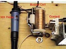
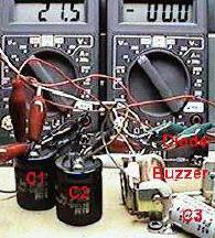
The picture shows: A 10 x probe which is reducing incoming measuring voltage for an oscilloscope. An electric coil (~1 k ohm resistance) from an old phone bell with buzzing mechanics operating a contact which is made from an old relay (coil removed). Back EMF is what you get when an electric current stops flowing through a coil. The more abrupt this stops the better the back-EMF.
For this experimental setup you can actually use any buzzer with an electric coil. The more windings that are on the coil the stronger the magnetic field in (or around) the coil will be and so will be the back-EMF. All you need to do is to build up a magnetic field and let it collapse again.
The buildup and collapse sequence should run at a frequency of 25-50 cycles/sec. That’s exactly what a buzzer is doing. Activate the buzzer with an appropriate DC power source. If you use a AC/DC transformer make sure the load is not too heavy for it. I used an adjustable transformer.
You do need an oscilloscope for exact measurements and you should use the 10x measuring probe if the created voltage exceeds the maximum. However if you do not own such a wonderful instrument you might use your fingers (at your own risk). If you feel nothing, try again with wet fingers. Forget your multi-meter, both analog and digital, because it’s not going to show those high voltage spikes.
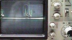
This is the typical image of back-EMF. The voltage spikes are more than 4 squares up, each square means 5 x 10 volts (due to 10 x probe). Certain tingling in fingers is felt when touching the blank wire. If it were not for the low amperage in this circuit the 200 volts spikes would have been dangerous indeed. All this from a buzzer at 10 volts and 3-4 mA(DC).
Back-EMF is what makes your spark plugs spark. But it is also an unwanted phenomenon in electrical engineering, for instance in DC motors where back-EMF causes sparking on commutators, eating up battery power.
How might it ever be useful for free energy? We’re getting to that.
How can we use this back EMF for free energy?
Based on the previous BACK-EMF Test, I tried the following setup to prove a gain of charge during a capacitor discharge (C1 into C2) through the buzzer, by collecting the BACK-EMF of the buzzer-coil in a third capacitor C3 (470 uf). I minimized the self-discharge of C1 and C2 by using higher quality capacitors (4700uf). For the diode (DRR 104) you can probably use any type. The faster the switching the less energy you’ll lose. The total charge of the system was at the start in C1 (21.5 volts). C2 and C3 were at 0 volts. After the buzzer stopped there is still some voltage flowing from C1 into C2. It takes a few seconds until C1 and C2 are balanced. Measurement showed C1 and C2 (11.4 volts) each! and C3 (25.2 volts). I had the buzzer working and ended up with more charge than I started with!
These capacitor discharge experiments prove that the electrons moving through a load are not used up but only slowed down giving some of their kinetic energy to do work in the load.
Conventional textbooks say that no charge but energy is lost in the connecting wires during such a discharge. Then what IS the difference between energy and charge? Theoretically it should be possible to pulse the charge in C2 through a transformer back into C1 ending up with 21.5 volts again. The question arises: Where is the bug in energy-calculations? Is there a difference between mechanical- and electrical power transmission?
If you want to check it out, here is the circuit. C1 and C2 are electrolytic capacitors with 4700 uf each. C3 is an electrolytic capacitor with 470 uf. For the diode any universal diode with appropriate working voltage will do it. I used (DRR 104). The buzzer is self-made from an old telephone-ringing coil and the contacts are from an old relay.
So how can we use this to build a free energy generator?
I believe there are 2 ways of doing it:
– By building a Solid State free-energy circuit
– By building a Mechanical generator free-energy machine
Solid state Free-energy circuit
It’s very simple actually. The idea is that we use what we have learned from the capacitor tests to create a circuit that uses the capacitors to run the load and then by discharging the 1/2 full capacitor into a DC-DC converter we can recharge the initial cap and start again. And have some energy left over!
Here’s how it works
Its very simple actually. First we charge C1 with 12 volts. Then we close S1 and discharge C1
through the motor and into C2. Now C1 and C2 are both at 6v and we got the motor to run for a while. Now make sure S1 is open and close S2. This discharges C2 into the DC-DC converter, which now charges C1 back to 12v. Open S2 and we can repeat it again and again…. And we now have Free energy! Then we just need to build a circuit to replace the manual switches.
# Free-energy generator (mechanical)
Well we have already proven that we have free energy available from doing the capacitor tests, now we need to come up with a way to convert that extra energy to be used in a closed loop system ie.. to charge a battery maybe. The problem with close looping it with a battery is that it is difficult to tell if the machine is running over 100% efficiency. Therefore I propose we use large capacitor banks. This way we can start the device with a battery and once it is up to speed, we disconnect the battery and let the capacitors do the rest. We will know if it’s running over unity right away if it doesnt stop within a minute or so.
# Heres how it will work
First off we add another capacitor C3. We build a device as shown with a high efficiency permanent magnet motor driving a generator.
We attach a 5 pound mass to the drive shaft of the motor to give us some extra inertia during switching. The whole system will require a bit of switching to enable it to work properly.
First we connect the external battery to the motor and let it spin up to speed. Next we disconnect the battery and C1 now discharges through the motor into C2. C1 and C2 now each have a 6-volt charge. Then our switching circuit discharges C1 directly across the motor with its 6-volt charge. Now C2 is discharged across the motor with its 6-volt charge.
Meanwhile the generator has been hooked to C3, which is now charged, and ready. C3 now switches connections with C1 i.e.. C1 is now being recharged by the generator and C3 is dumped through the motor into C2. The cycle then continues. The system will operate over unity just as our simple capacitor tests proved.
Of course we will have losses due to friction, and poor transfer efficiency. But remember we had a 50% energy surplus with our capacitor tests and 33% energy surplus under load conditions. So we have a lot of energy to play with.
Now just tap the energy off of the generator output and you have FREE-ENERGY!
# Parts Source
Electronic
– Jameco: Electronic Components and Computer Products
Phone: 1-800-831-4242
website: www.Jameco.com
Address: 1355 Shoreway Rd., Belmont CA 94002-4100
– All Electronics Corporation: New and surplus electronic parts and supplies
Phone: 1-800-826-5432
website: www.allcorp.com
Address: 905 S. Vermont Ave., Los Angeles, CA 90006
– Hosfelt: Electronics inc.
Phone: 1-800-524-6464
website: N/A
Address: 2700 Sunset Blvd., Steubenville, OH 43952-1158
– Mouser Electronics
Phone: 1-800-346-6873
website: www.mouser.com
Address: 958 N. Main, Mansfield, TX 76063-4827
– Digi-Key: Your ultimate destination
Phone: 1-800-344-4539
website: www.digikey.com
Address: 701 Brooks Ave. South, Thief River Falls, MN 56701-0677
– Electronic Goldmine: Catalog of high tech electronics and components
Phone: 1-800-445-0697
website: www.goldmine-elec.com
Address: P.O. Box 5408, Scottsdale, AZ 85261
Parts
– Small Parts Inc.: Engineering Findings Quality Components, Materials, and Tools
Phone:1-800-220-4242
website: www.smallparts.com
Address: 13980 N.W. 58th Court, P.O. Box 4650, Miami Lakes, FL 33014-0650
– United States Plastic Corp.: World’s Largest Assortment of Plastics
Phone: 1-800-537-9724
website: www.usplastic.com
Address: 1390 Neubrecht Rd., Lima OH 45801