Remark: A very clear and simple explanation of Bearden Concept to Harvest Free Electricity
THE FINAL SECRET OF FREE ENERGY, © 1993 T. E. Bearden
A.D.A.S. , P.O. Box 1472, Huntsville, AL 35807
February 9, 1993, (slightly revised March 23, 1993)
Foreword
This paper contains the real secret of tapping the vacuum energy very simply, using almost any source of potential (battery, electrostatic generator a la Swiss electrostatic device (the Testatika), elevated wire wire/250 V/m in the earth/ionosphere potential, etc). The objective is for the moderately technical reader to understand how to build and understand not only a single device, but also hundreds of different kinds of them. While it is quite simple, the “magic principle” contained in this paper only took me some 30 years to discover.
The precise definitions necessary to understand the free energy rationale are included. Also included are some very simple pseudo equations for the process. Do not underestimate these simple pseudo equations — they tell the tale that’s needed.
Also, there has been little or no time to “dress up” the paper. It’s simply written down very informally, to get the necessary points across. Nearly everything fundamental that we’ve been taught about EM energy is wrong or incomplete. Even the definition of energy in physics is wrong! Let me summarize a few of the things that are wrong with the classical electromagnetics (CEM) model as follows:
CEM is still utilizing a model based on a material ether. Although the Michelson-Morley experiment destroyed the material ether assumption in 1887, the classical EM model has never been corrected. It also contains no definition of charge, and no definition of potential. In many cases, algorithms to calculate a magnitude are boldfacedly and erroneously advanced as “definitions.” CEM still prescribes the force fields as the causes of all EM phenomena; it has been known since 1959 that forces are effects and not causes, that EM force fields exist only in and on the charged particles of mass in the physical system, and that the potentials are the primary causes of EM phenomena. The lack of definitive definitions of mass and force in mechanics is carried over into EM theory; there is no adequate definition of EM force or of EM mass. The magnitude of the electrical charge on an electron is not quantized. Instead, it is discretized, being a function of the magnitude of the virtual photon flux (VPF) exchange between the vacuum and the charged particle. When the charged particle is placed in a potential that differs from ambient, then the magnitude of the VPF — and hence the magnitude of the electric charge on the electron — is altered. The CEM assumption of an “empty vacuum” is totally falsified by modern quantum mechanics. The CEM notion that EM force fields and force field waves exist in vacuum is totally false. Only potentials and potential gradients exist in the vacuum. EM waves in vacuum are not force field waves as CEM prescribes; instead, they are oscillations of potentials and potential gradients. Potentials have a bidirectional EM wavepair structure, where the bidirectional wave pairs are phaselocked in a harmonic series. In each wave pair, photons and antiphotons are continually coupling (into spin-2 gravitons) and decoupling. This is where gravitation and electromagnetics are unified. The CEM notion that singular EM forces exist in either matter or the vacuum is false; Newton’s third law requires that
all forces exist in oppositive pairs. Not a single one of the equations universally taught as “Maxwell’s equations” ever appeared in any book or paper by James Clerk Maxwell; instead, they are Oliver Heaviside’s equations. Maxwell’s actual theory was written in quaternions, which is a complete system of mathematics. The Heaviside/Gibbs vector version
(1) has a lower topology,
(2) is not a complete system of mathematics, and
(3) actually captured only a subset of Maxwell’s actual theory.
Tensor theory does not recapture that which was lost.
There are even more errors in CEM, but these should suffice to make the point: Classical electromagnetics theory is seriously flawed, with archaic foundations, riddled with errors, and it should be completely redone. Until this revamping of CEM is accomplished, the present model solidly blocks free energy, antigravity, a unified physical field theory, and a unified theory of mind and matter interaction.
A second paper this year will detail the exact long-term causative mechanism for cancer and leukemia, and the exact mechanism for essentially 100% cure of terminal tumors in laboratory animals, demonstrated by the Priore team in France in the late 1960s and early 1970s. The same mechanism can be used to cure AIDS.
Throughout the world, humankind is suffering. In the poor populations of the world, early death is the norm, as is frequent famine. One third of the human race goes to bed hungry each night.
Protein starvation of children is common. One third of the human race is infected with worms.
Many other diseases ravage the far-flung poor peoples of the world. They have little or no industries. They have no abundant electrical power. They have little education, and little modern knowledge. They have little or no medical treatment. In short, they are born without hope; live in misery, filth, disease, and poverty, and die without dignity.
Meanwhile, the factories, cities, and enclaves of the “developed and developing” worlds belch forth fumes, toxic and hazardous wastes, and pollutants. They also spew forth weaponry which for one reason or another is used to arm the poorer nations, for use in destroying themselves and their impoverished neighbors. Warfare, terror, banditry, despotism, and all the four horsemen of the Apocalypse are truly loosed in the earth.
We simply must do better than that. And we can do better than that! But to do better, we’ve got to make the basics available to impoverished nations, cheaply and easily. Primary among their needs are energy and medical treatment. Given those, populations can be stabilized, people educated, development begun, and the living standard drastically elevated.
So that is the immediate goal. In this paper, I am freely giving away what required me an arduous 30 years of my life to discover. Shortly we will also detail the new methodology for a new therapeutic science, hopefully to cure the diseases that ravage humanity.
God willing, this paper will trigger a thousand, or even ten thousand, scientists and engineers to develop overunity energy devices. If so, shortly we can rid our biosphere of noxious automobile and factory exhausts, radioactive nuclear wastes, and massive oil spills. We can remove many of the hydrocarbon combustion pollutants from the air, stop acid rain and the destruction of our forests, and stop the steady rise of carbon monoxide in our air. If that truly tends toward a “Greenhouse” effect, then we can halt that effect as well.
The Creator has always given us bountiful free electrical energy, everywhere, easily and readily for the simple taking. It has only been our own blindness and folly that have prevented us from seeing and using this free energy bounty.
So here is the final secret of abundant, free electrical energy. Please use the knowledge well and see that its benefits also accrue to those impoverished ones who need it so desperately.
Remember the adage, “Inasmuch as you have done it to these little ones…”
This is for those little ones. You are our brothers and sisters. We want you to live. And we want you to have a better quality of life, not just bare existence. We care.
Tom Bearden, February 9, 1993
THE FINAL SECRET OF FREE ENERGY© T. E. Bearden 1993
Some Definitions
The Quantum Mechanical Vacuum: First we need some definitions. We start by assuming the quantum mechanical vacuum.1 Empty “spacetime” is filled with an incredibly intense flux of virtual particles. It is a plenum, not an emptiness. We shall be interested only in the fantastic flux of virtual photons, for we are discussing electromagnetics.
Energy and Potential: Energy is any ordering, either static or dynamic, in the virtual particle flux of vacuum. EM energy is any ordering, either static or dynamic, in the virtual photon flux (VPF) of vacuum. That is, for a particular kind of “field” energy, we simply choose the so-called quantum particle of that field, and consider only that kind of virtual particle flux.
Potential is any ordering, either static or dynamic, in the virtual particle flux of vacuum. Hey!
That’s exactly the same definition as energy. Quite correct. Energy and potential are identically the same. Neither is presently defined correctly in physics.
Energy is normally defined as “Energy is the capacity to do work.” That’s totally false. Energy has the capacity to do work, because work is correctly defined as the dissipation (disordering; scattering) of energy (order). The scattering of energy is work. It is not energy! I.e., energy is not definable as its own scattering!
Look at it this way: A man has the capacity to catch fish. That is true, but it is not a definition, since a definition must in some sense be an identity. You cannot say that a man is the capacity to catch fish! That may be a submitted definition, all right, but it is false. Similarly, energy has the capacity to do work; that is one of its attributes. But energy IS the ordering in the VPF (we are referring from now on primarily only to EM).
Scalar and Vector Potentials: The scalar potential is any static (with respect to the external observer) ordering in the VPF of vacuum. The vector potential is any dynamic (with respect to the external observer) ordering in the VPF of vacuum. We shall be interested in the electrostatic scalar potential. So it is a static ordering — a stationary template — in the VPF of vacuum, much as a whirlpool is a stationary ordering (template, form) in the rushing flow of a river.
The Scalar Potential Has An Internal Structure
The Structure of the Scalar Potential: According to rigorous proofs by Whittaker2 and Ziolkowski,3 any scalar potential can be mathematically decomposed into a harmonic series of bidirectional wave pairs. Figure 1 shows this Whittaker/Ziolkowski (WZ) structure. In each pair, the forward-time wave is going in one direction, and its phase conjugate (time-reversed) replica wave is going in the other. According to the so-called distortion correction theorem4 of nonlinear phase conjugate optics, this PCR wave must precisely superpose spatially with its partner wave in the pair. The two waves are in-phase spatially, but 180 degrees out of phase in time. The wave is made of photons, and the antiwave (PCR wave) is made of antiphotons. It follows that, as wave and antiwave pass through each other, the photons and antiphotons are coupling and uncoupling with each other, because the antiphoton is a PCR photon, and PCR’s precisely superpose spatially with their partner. A photon or antiphoton has wave characteristics, because it has a frequency; if the wave aspects are perfectly ordered and perfectly correlated, then so are the photon’s particle aspects.
A Potential Is An Ordering Across the Universe: So we have — astoundingly — perfect VPF inner ordering infolded in the electrostatic scalar potential! We also have perfect wave/antiwave ordering infolded in there. When you collect a simple set of charges on a small ball or in a region, the scalar EM potential from that set of charges reaches across the universe. In it you have an infinite harmonic series of phase-locked time-forward EM waves going out from the charges to all distant points of the entire universe. And you have an infinite harmonic series of phase-locked time-reversed EM waves coming from all points of the universe, back to the “collected charges” source.
A Potential Is A River of Energy: The point is, you have established a mighty, hidden, 2-way river of energy between that collection of charges and every other point in the universe. There is infinite energy in each of those infolded waves and antiwaves. But in a localized region, the energy density in each wave is finite. Since in finite circuits the potential interacts with a localized set of mass, we shall be concerned with the local energy density (joules/coulomb) of the potential .
But forget the conventional myth of visualizing the potential as pushing a unit charge in from infinity “against the force field” — there isn’t any force field in the vacuum, as is well-known in quantum mechanics. Also, Newton’s third law requires all forces to occur in pairs — each pair consisting of a force and its 3rd law reaction force. From that viewpoint alone, there is no such thing as an EM forcefield or force field wave in the vacuum. There are just gradients of the vacuum potential present in the vacuum. In the vacuum, an EM wave is actually a wave of the phase locked gradients of the electrostatic scalar potential and of the magnetostatic scalar potential. And each such gradient wave is simultaneously accompanied by its phase conjugate gradient wave, because of Newton’s third law.
Newton’s third law requires forces to occur in pairs of equal but antiparallel forces.
Both wave and antiwave co-exist simultaneously in the vacuum EM wave.5 Therefore it’s a stress potential wave, not a force field wave. It’s more like an electromagnetic sound wave,6 and so it is a longitudinal wave, not a transverse wave. In the EM vacuum wave’s interaction with matter (the so-called “photon” interaction), the wave normally half interacts with the electron shells of the atom, giving translation forces, while the anti-wave half interacts with the atomic nucleus, giving the Newtonian 3rd law reaction (recoil) forces (waves). The EM wave in vacuum is an electrogravitational wave.
Energy Is Internally Infinite and Unlimited: A static potential — which is identically excess energy — is internally dynamic and infinite. Energy is internally infinite and unlimited! But it has a finite energy density in a local region of spacetime. Since energy interacts with matter locally, we shall be concerned with the local energy density (joules per coulomb).
A Principle of Great Importance: The only way you can have a “chunk” or finite amount of energy to dissipate in a circuit as work is to first have a potential’s local energy density interactwith a local finite mass collector. The normal interacting mass collector is the free electrons (the free electron gas) in the circuit. You can have, e.g., (joules/coulomb x coulomb); (joules/gram x grams); (joules/m3 x m3); etc.
Voltage, Force, Potential Gradients, Loads, and Work: Now let’s look at circuitry aspects. Conventionally they are a mess. Voltage is “essentially” defined as the “drop in potential.” In other words, it’s the dissipation (disordering) of a “finite amount” of potential gradient. But the only way you can get a “finite amount” of infinite energy/potential gradient is by first interacting the potential gradient’s internal, finite, excess energy density with a finite “collector” mass. E.g., (joules/coulomb available for collection) x (coulombs collecting) = excess joules collected on the interacting coulombs, available for dissipation.
So voltage is really the dissipation of a finite collection of excess EM energy/potential gradient.
The dissipation of potential or of its gradient is not potential! You cannot logically define either potential or energy as is own dissipation!
We presently use the notion of “voltage” in two completely contradictory ways in electrical physics. Here’s how we got the confusion: We take a potential gradient (which has a local energy density), and we “collect” it across some charged masses in a locality — usually the free electrons in the free electron gas in our circuitry. That is, we express the finite energy density of the potential gradient (before collection onto charges) in the local region in terms of energy per coulomb. The potential gradient actually is a change to the ambient potential, and so it contains an excess energy density (the magnitude may be either positive or negative). We then collect this potential (actually this potential density) on a certain number of coulombs, which places tiny little gradients of potential across (coupled to) each free electron. The local excess energy density of the potential gradient multiplied by the amount of collecting mass gives the amount of excess energy collected (on the interacting charges/coulombs). On each collecting particle, that little gradient, together with the coupling particle, constitutes a tiny force. F is not just equal to ma (non relativistic case); instead, F==ma), where (mass x acceleration) is considered as a unitary, inseparable thing. So that little potentialized electron (that little EM force) moves itself around the circuit. In the load (scatterer), the little potentialized electron (the little force) is subjected to jerks and accelerations, thus radiating energy (shucking its gradient). Since this is done in all directions in the scatterer (load), that gets rid of the gradient, reducing the “little force” (potentialized electron) to zero because the little potential gradient is lost due to radiation.
Collecting And Dissipating Energy
Energy Dissipation and Collection: Without further ado, we consider the scalar potential’s local energy density in terms of joules per coulomb. That is, in a specific glob of charges (i.e., in finite circuits), the amount of energy collected from a potential gradient onto the finite number of charges receiving/collecting it, is equal to the number of joules of energy per coulomb that is in the potential gradient, times the number of coulombs collecting (receiving) the potential gradient. The current is the activated (potentialized) coulombs per second that dissipate their potential gradients during that second. The current multiplied by the time the current flows gives the activated coulombs that dissipated their activation (potentialization) during that flow time.
Dissipating, activated coulombs multiplied by the excess energy collected per activated coulomb gives the energy dissipated (the work or scattering done) in the load.
We define collection as the connection of a potential gradient (a source) to the charged masses in a circuit element (the element is called the collector), which for a finite delay time does not allow its potentialized free electrons to move as current. In the collector, during this delay time these trapped electrons are “activated” by potential gradients being coupled to them.
Technically, that delay time in the collector is known as relaxation time,7 in the case of the free electron gas8 (in a wire or in a circuit element). A collector then is a circuit element that has a usable, finite relaxation time. During that relaxation time, the trapped electrons are potentialized without movement as current; each collecting/receiving free electron gets a little gradient across it, but no current yet flows. In other words, during this finite relaxation time (collection time), we extract potential from the source, but no current. Thus we extract energy (potential), but no power (which is voltage x amperage). During the relaxation time, we extract from the source only a flow of VPF, which is continually replaced in the source by the vacuum’s violent VPF exchange with the source’s bipolarity charges. We do not extract power from the battery/source during relaxation time, but we extract free energy density. That free energy density, coupling with a finite quantity of electrons, gives us a collected finite amount of energy. With that background, let’s start again, and go through this in a useful “free energy” manner.
The Electron Gas. We refer to the conventional model of the free electron gas in a wire.9
Although the electrons in this gas actually move by quantum mechanical laws and not by classical laws, we shall simply be dealing with the “on the average” case. So we will speak of the electrons and their movement in a classical sense, rather than a quantum mechanical sense, as this will suffice very well for our purposes.
When one connects a circuit to a source of potential gradient (say, to a battery), the first thing that happens nearly instantly is that the potential gradient races onto the coupling wire and heads down it at almost the speed of light. As it goes onto the wire, this gradient “couples” to the free electrons in the free electron gas. However, inside the wire, these electrons can hardly move down the wire at all; they can only “slip” once in a while, yielding a “drift” velocity of a fraction of a cm/sec.10 On the surface, things are just a little bit different. Most of the “current” in a wire, as is well-known, moves along the surface, giving us the “skin” effect. [For that reason, many cables are stranded of finer wires, to provide more skin surface per cm3 of copper, and hence more current-carrying capability per cm3 of copper.]
So, initially, little gradients of potential appear on and across each free electron, with a single little Del* on each electron, and coupled to it. The couplet of [Del* x me], where me is the mass of the electron, constitutes a small nEe. [This is rigorous; the conventional EM notion that an E field exists in the vacuum is absurd, and it is well-known in QM that no observable force field exists in the vacuum. As Feynman pointed out, only the potential for the force field exists in the vacuum,11 not the force field as such. Or as Lindsay and Margenau pointed out in their
Foundations of Physics, one does not have an observable force except when observable mass is present.12]. We have stated it even stronger: Not only is F = ma, but F==ma (nonrelativistic case).13 Since no observable mass exists in vacuum, then no observable F exists there either.
Force, Coupled Gradients, and Electron Translation
Electrons Coupled to a Potential Gradient Move Themselves. The point is, when activated by a “coupled potential gradient,” the activated electron moves itself until it loses its activation (its coupled potential gradient).
Let me say that again, in a little more detail. Forget the standard notion that a force field such as the E-field causes electrons to move. Also forget the notion that the E-field is given by E = -Del*.
In foundations of physics, those equations are known to be incorrect for the vacuum. EM force fields are known (in QM foundations theory) to be effects, existing only in and on the charged particles, and not existing separately at all,14 or in the vacuum at all.15 Instead of E = -Del*, in the vacuum the correct equation would be something like this: PE = -Del*. In this case, we have correctly stated that the potential gradient PE provides the potential for producing an antiparallel E-field in and on a coupling/collecting charged mass, and the magnitude and direction of that potential gradient will be given by -Del*, if and only if a charged mass particle is first introduced so that it couples to PE.
At any rate, the activated/potentialized electron moves itself. The reason is that it constitutes a force. Force == (mass x acceleration) (non relativistic case). So the potentialized/activated electron is continuously accelerating. However, it is prevented from easily moving down the wire directly. To begin to do that, it essentially has to first move to the outer skin of the copper conductor.
The Collector: We now consider a circuit element that we called a collector. (It could be a special coil made of special material, a capacitor with doped plates rather than simple conducting plates, or any one of a number of things). The objective is for the collector to be made of special material so that it has a free electron gas whose electrons are momentarily not free to move as current (they continue to move violently around microscopically, but essentially with zero net macroscopic translation) for a finite delay (relaxation) time, while they are settling themselves upon the surface and preparing to move as current. Let’s call the electrons NNTE (no net translation electrons) during that finite delay (relaxation time). During that “no-current” delay time, the NNTE electrons become potentialized/activated by the potential gradient impressed across the collector. So at the end of the NNT time, the NNTE electrons are potentialized, and each is of the form [.öme].
The Secret of Free Energy
Two Circuits/Two Cycles: We are going to use two circuits and two cycles, as shown in Figure 2:
(1) We shall connect a collector to a primary source of potential (to a battery) during the short time that current does not yet flow, but potential does. (In other words, during the relaxation time of the collector, we allow the VPF to flow onto the NNTE electrons of the collector and potentialize (activate) them, but do not yet allow the electrons themselves to flow as current, but only to move transversely in the wiring and collector.) This is cycle one of a 2-cycle process:
This is collection of a specific amount of current-free potential gradient — power-free energy — off the potential-source (the battery) onto a collector. During the collection cycle/time, current does not and must not flow (we are discussing the ideal case). We are freely “charging up” the collector as a secondary battery/source.
(2) At the end of the collection (potentialization/activation) time/cycle in circuit one, the potentialized collector (the charged secondary source) is sharply switched away from its connection to the primary potential source (the battery), and at the same time it is instantly switched into a separate closed circuit with the load. This is important: In cycle two, the potentialized collector (with its finite amount of excess trapped EM energy) and the load are connected in a completely separate circuit, and one that is closed, with no connection at all to the original source of potential (in this case, to the battery). Specifically, this “load and potentialized collector” circuit is completely separate from the primary source; during cycle two the primary source (the battery) is not connected to anything.
In other words, all we’ve taken from the primary source (the battery) is cur ent-free, force-fieldfree potential gradient. So to speak, we’ve taken a “chunk of potential gradient” from the source, nothing else. You simply multiply the potential gradient’s local energy density (the so-called “voltage”, which is really excess joules per coulomb) by the number of coulombs of charge that is “activated” (that “collects” this voltage or excess joules/coulomb) in the collector. Specifically, we have not taken any power from the battery itself, and so we have not done any internal work inside the battery upon its internal resistance, by a “closed circuit electron flow” back into the battery. We have not permitted such a flow.
Instead, we are using the activated collector as a temporary, secondary battery. We will utilize this secondary battery in a conventional manner to power the load, which will also kill the secondary battery (dissipate its trapped EM energy). But that will not affect the primary source.
The primary source is never used to directly power the load. It is only used as an infinite source of potential gradient (i.e., as an infinite source of energy density).
The Standard Power Extraction Circuit
The Conventional Circuit: We digress momentarily: In the standard electrical method, the potential source (which is a bipolarity) is connected across the load. This connects both the external load and the internal resistance of the battery itself in series, as the “total circuit load.”
Electrons then pour through the external load circuit and through the internal battery resistance, from the “electron rich” polarity of the source to its “electron poor” opposite polarity. The scattering of energy in the internal battery resistance is actually doing work to upset the chemistry that is maintaining the battery’s charge separation (the bipolarity). In this manner, the source’s separation of charges (which is the “gate” furnishing the potential/energy gradient) is being destroyed as the current flows, and this in turn destroys the source of the potential gradient.
In other words, normally we, engineers, are trained to kill the bipolarity, which kills the potential source itself! Incredible as it may be, we, engineers and scientists, have been trained to utilize the free “trapped EM energy” furnished by nature through the source, to destroy the source of the energy/potential, with the same vigor as they power the external load! In fact, our teachers simply have never learned any other way to do it except this deliberately “self-destructive” manner!
A Waterwheel Analogy
Imagine, if you will, a waterwheel that powers a mill, with a sluice gate upstream in a river, that diverts some river water into the sluice carrying water to the wheel when the sluice gate is opened into the river. The diverted water flows down to the waterwheel, turning it, and the spent water is fed back into the river below the mill site. Now what fool would connect a pulley onto the waterwheel, with a rope running from the pulley to the sluice gate, so that when the wheel rotated, part of the rotational power also was utilized to close the sluice gate and shut off the water, stopping the waterwheel? If one did so, when the sluice gate was opened, the waterwheel would rotate only until the sluice gate was closed, shutting off the water. Then one would laboriously have to pay to reopen the sluice gate again, then again, then again. No selfrespecting “waterwheel engineer” would do such an unthinkable, insane thing. But that’s exactly what we engineers, electrical physicists, and scientists have been trained to do! We have no energy engineers or energy scientists at all; instead, we have all been power engineers and power scientists. We have all been energy source killers! In this paper, we shall try to do better, and rectify “one of the most remarkable and inexplicable aberrations of the scientific mind which has ever been recorded in history,” as Tesla called the conventional electromagnetics.16 By being energy engineers, we shall only have to pay for our energy source once, and then we shall draw as much energy from it as we wish.
External Load Power Is Free; Only The Power In The Source Costs
Here’s the magic secret of free electrical power: The power in the external load is absolutely free, and it always has been free.17 In any load circuit, the only power you have to pay for, and have ever had to pay for, is the power you incorrectly use to kill your own primary source. The only power that “costs” more effort/dollars is the power erroneously utilized inside the source to “close the gate” and kill the primary source. Your electric power company doesn’t pay for any of the collected energy on your load circuits that is dissipated to power your house. Instead, the power company charges you for its own ignorance. It charges you for its insane use of its own freely extracted electrical energy to continually kill the bipolarity in each of its generators, thus continually killing the free electrical source of that generator’s energy.18
In any electric circuit, we can continue to indefinitely power the external load indirectly from a source, so long as we are not so naive as to use any of the free energy we extract from the primary sou ce to dissipate back inside the primary source itself and shut it off!
And we can easily and freely multiply electrical potential. As an example, given a single good source of potential, a hundred radial wires can be connected to the source. The same potential will now appear at each of the ends of the hundred wires. A switcher/collector unit can then operate from each radial line’s end, and power external loads, without “loading” the original primary source. This “cascading” can be continued indefinitely. A single power plant, e.g., can power the entire electrical grid of the United States. And a single automobile battery can power a large, agile, electric automobile at highway speeds, with sports car acceleration, with unlimited range, without “refueling,” and with no noxious chemical exhaust.
Obvious Impacts
Environmentalists should immediately see that the chemical pollution of the biosphere by mechanista and processes to obtain energy can be dramatically reduced, to almost negligible levels. The e need be no huge oil tanker spills, for there need be no huge oil tankers. There need be no worrisome radioactive wastes from nuclear power plants, or abandoned hazardous nuclear plants when their life is finished, because there need be no nuclear power plants. There need be no noxious exhausts from jet airplanes (which are really what is diminishing the ozone layer and punching holes in it), automobiles, trucks, buses, innumerable coal-fired and oil-fired power plants, etc.
The Electronic Smog Problem
In fairness we point out that, as the usage of free electrical energy mushrooms, we will be dramatically increasing the low-level EM signal density of the environment, and that too is biologically detrimental. Although beyond the scope of this paper, that cumulative biological damage mechanism has also been uncovered by this author. A formal paper is presently in preparation for presentation in March 1993 at the annual meeting and conference of the
Alabama Academy of Science.19 The paper will also present an entirely new definition of cancer, give its exact long-term cumulative mechanism, and give an exact, scientifically proven mechanism for eliminating cancer, leukemia, and other debilitating diseases such as AIDS. For our purposes here, we simply state that we understand the EM “electronic smog” biological damage mechanism, and how to go about developing a total counter for it. Eventually, we would see a small “counter unit” added to each power unit, alleviating the “electronic smog” problem and preventing biological damage.
Only Dissipate Energy From a Collector, Not the Source
Completion of the Collection Cycle: But to return to the completion of our collection cycle (cycle one). During collection, we have not extracted power from the source. That is vital . We have not moved the gate through which our source is furnishing free energy. We have not diminished our primary source. From our previous definitions of potential, we have indeed extracted trapped energy from the primary source, because we placed its “local energy density” across a certain finite collector/mass, instead of extracting power (dissipating energy inside the source or battery to spoil its chemistry and deplete its charge separation).
All Energy Is Free
Here’s the incredible truth. The entire universe is filled with mind boggling free energy everywhere, in the simplest of things. Simply scrape your feet on the carpet, and you will collect perhaps 2,000 “volts” on your body. At that time, hidden EM energy is flowing from every point in the universe to your body, and from your body back to every point in the universe. We know that all macroscopic matter is filled with stupendous amounts of electrical charge. So an incredible river of energy — a great flux — is driving every single thing, from the smallest to the largest. Opening a gate to extract trapped EM energy is simple. Just collect a bit of charge, or scrape your feet hard, or comb your hair briskly. All we have to do is not be stupid and close the gate once we’ve got it opened!
God has been most kind. We have nothing but free energy everywhere. All energy is furnished to us freely! It’s our own blindness that has made us into energy source killers. All we have to do is open our eyes to the truth of nature’s incredible energy bounty. We must just freely collect that bountiful fruit from Nature’s tree, instead of chopping down the tree and killing it.
Dissipating The Collected Energy
The Work Cycle: We focus again on cycle two. Shortly after the now-potentialized collector is connected to the load at the beginning of cycle 2 (the power cycle, or energy dissipation cycle, or work cycle), the potential gradient across the potentialized collector is connected (transferred) across the free electrons in the load circuit. We assume that the material of the collector and the switching time have been designed so that, shortly after switching to the loading/work cycle, the activated/potentialized free electrons in the electron gas in the collector reach the skin of the collector, and are free to move as current.
So just after the beginning of cycle two, each of the free electrons in the load circuit now is potentialized and free to move down the wiring. Each potentialized (activated) electron has its own little individual potential gradient across it and coupled to it, due to the overall potential gradient from the collector. Remember, prior to coupling to charges, this potential gradient moves through the circuit at light speed. An EM potential gradient coupled to a charged mass constitutes an EM force field (excess trapped EM energy per coulomb, times the number of collecting coulombs). Now each little free electron with its potential gradient forms a little E-field (force/charge), and that little E-field (force/charge) is free to move. That’s all it takes to move (accelerate) the little activated electron’s mass through the load (the scatterer). We strongly stress that the potentialized/activated electron moves itself. It doesn’t care whether or not the external battery is attached or not. It is its own little motorboat, with its own little engine driving it.
As the little potentialized electrons reach the load (the scatterer), they bang and clang around in there erratically. That is, the “scatterer” (load) causes spurious accelerations (“scatterings”) of these self-driven electrons. As is well-known, when a charge is accelerated, it radiates photons.
What actually happens is that these little “jerked around” electrons shuck off their little potential gradients in the load (in the scatterer, or the “jerker-arounder”) by emitting/radiating photons in all directions. Hence the heat that is produced in the load; the heat is just these scattered photons. The theory of calorimetry already states that all the excess energy (on the potentialized electrons) will be dissipated as this heat (scattered EM energy).
When all the potentialized electrons have radiated away their potential gradients in the load (scatterer), they are no longer potentialized. The free electron gas is again “quiescent” and no longer potentialized/activated (again, we are talking about “on the average” from a classical viewpoint).
Repetition and Review
Notice What We’ve Done: We took some trapped EM energy density (a chunk of potential gradient, a “voltage” before current flows) from the source, by switching that potential gradient (energy density, which is joules per coulomb) onto a collector (containing a certain number of coulombs of trapped charges) where the potential gradient activates/potentializes/couples-to these temporarily non translating electrons. So the finite collector collected a finite amount of excess energy [joules/coulomb x collecting (trapped) coulombs] on its now-excited (activated) free electrons. Then, before any current has yet flowed from the source, we switched that potentialized collector (with its temporarily restrained but potentialized electrons; with their finite amount of excess trapped EM energy) away from the source and directly across the load.
Shortly thereafter, the relaxation time in the collector expires. The potentialized electrons in the collector are freed to move in the external load circuit, consisting of the collector and the load, and so they do so. The scattering “shock collisions” due to the erratic electron accelerations in the load shake off the little potential gradients on the conduction electrons, emitting photons in all directions, which we call “heat.” In shaking off the photons, the electrons lose their little potential gradients, hence lose their activation (excess EM energy).
Rigorously, we have extracted some energy in trapped form, and allowed it to dissipate in the load, “powering the load” for a finite discharge/dissipation time and doing work.20 Contrary to the conventional electrical power engineering, we have also done this without doing any work inside the source to diminish its ability to furnish potential gradient.
What Is Energy In An Electric Circuit?
Energy in an Electric Circuit: Here’s the principle loud and clear. Energy in an electric circuit involves only the potentialization and depotentialization of the electron carriers in that circuit.21Itinvolves only the potential gradient (the joules per coulomb) collected by the circuit to potentialize its electrons, and the number of coulombs of electrons that are potentialized during the collection phase. Electric circuits simply utilize electrons as carriers of “potential gradients,” from the source to the load, where these gradients and the activated electrons constitute excess trapped EM energy. In the “shocking/scattering” occurring in the load, the jerking (acceleration) of the electrons causes these activated (trapped-energy-carrying) electrons to shuck off their potential gradients by emitting them as scattered photons (heat).
If one is thoughtless enough to allow the primary potential source to remain in the circuit during the “work” phase, then one is using the potentialized electrons to also go back into the primary source and scatter energy from its internal resistance (internal load), thereby disorganizing the organization that was producing the source potential and energy in the first place. If one does that, then all the while one is getting some work (scattering of energy) in the load, one is also steadily getting some work done inside the primary source to steadily destroy it! Literally, one is killing the goose that lays the golden eggs.
Continued Operations: But back to our circuit. After we complete one full collection/discharge cycle, we wish to continue producing work in the external load. So we simply switch the collector back away from the load and onto the primary source, collect some more current-free potential, and again independently switch the collector with its repotentialized free electrons back across the load. We can repeat this two-cycle process to potentialize the external load and power it as long as we wish, from a battery or other source of potential, and never take any power at all from the primary battery. We do not need to drain the battery or source at all, in order to power a load, unless we attempt to power it directly. Powering the external load is always free!
Nature has been most kind, and we have been most ignorant. You can have all the trapped electrical energy you wish, from any source of potential, for free. You can power all the external loads you wish, for free, by using a collector as a secondary source, and simply shuttling potential between the primary source and the collector.22 But you cannot have power for free from (in) the potential source. If you allow current flow in your collection cycle, you are depleting the separated charges inside the battery that are furnishing the source potential.
The Coal-Fired Locomotive
Rigorous Analogy of a Coal-Fired Locomotive. Now here’s an exact analogy, to assist in understanding. Imagine a coal-fired train, and a fireman shoveling coal. He has an external load/scatterer of energy (the fire in the firebox under the boiler). He has a primary source of potential/energy (the coal car). No fireman in his right mind would ignite the coal in the chute of the coal bin, to try and get some heat energy into the firebox! [That is, he would not attempt to extract power from the source. Yet that’s exactly what all we engineers are trained to do at present.] Instead, the fireman takes out (collects) a finite amount (a shovelful) of coal (trapped energy). Coal per se (the potential gradient) has a certain energy density per unit volume (trapped joules per unit volume of coal) and the shovel (collector) has a certain volume.
Accordingly, the shovelful of coal contains a certain amount of trapped joules of energy. In the fireman’s shovel (the collector), the energy remains in totally trapped form, as coal not afire and without its trapped energy being dissipated as work. [He doesn’t act like a fool and ignite the coal in the shovel either!] He then throws that shovel of coal (collected trapped energy) onto the fire (scatterer), completely separately from the coal bin/source. He continues to repeat his shoveling cycle, and each shovelful of coal added to the fire dissipates additional energy, powering the load.
The Free Energy Principle
All potential gradient (trapped excess energy density) is free for the taking.23 The potential is due to the violent VPF exchange between the vacuum and the separated bipolar charges furnishing the source potential gradient. The energy of the entire universe is flowing through that source potential. You can have as much of this internal VPF flux energy (potential) as you wish, as often as you wish, so long as you don’t demand current (which is power, or the rate at which the energy is being freed and dissipated). It’s really simple. You can have all the trapped energy you wish, from any source. You cannot connect to the source and start to dissipate the energy as power, however, without starting to close the “gate” from which your free trapped energy is coming.
In other words, here’s the iron rule: If you draw current, you kill the bipolarity gate furnishing the potential gradient (source of energy density). In that case, you kill the source. If you do not draw current, you do not kill the bipolarity gate and you do not shut down the source. In that case, you can continue to “use” it and extract trapped EM energy from it forever.
Definitions Again
Definitions: I’ll put down some simple equations, that may help to explain it more exactly. Firstwe repeat some definitions.
Energy is any ordering imposed upon the virtual particle flux of vacuum. EM energy is any ordering imposed upon the virtual photon flux of vacuum. Static energy is an ordering (a template) which is stationary with respect to the external observer. Dynamic energy is an ordering (a template) which is not stationary with respect to the external observer.
Potential: Any ordering imposed upon the virtual particle flux of vacuum. Scalar potential is an ordering (template) that is not moving with respect to the external observer. Vector potential is an ordering (template) that is moving with respect to the external observer.
The scalar EM potential is any static (with respect to the external observer) ordering imposed upon the virtual photon flux of vacuum. Etc.
Note again that energy and potential have exactly the same definition. Potential is in fact trapped energy. Scalar EM potential is static EM energy (to the external observer) or trapped (collected) EM energy. In other words, if one takes off a differential of potential onto a fixed number of coulombs, one takes off a certain magnitude of trapped EM energy. In other words, one takes out a shovelful of coal from the coal car.
Importance of Separation of Charges
We Must Not Dispel the Separation of Charges In Our Source: The difference in our coalfired train analogy and our electrical circuit is that, in the coal train, the coal in the coal car is not automatically and continually replenished. Also, the coal in the coal car has already been collected by the mass of the coal car, so it is not infinite. In the electrical circuit, the potential gradient in the primary source is continually replenished, automatically, and it is infinite (though it has a finite energy density). The reason is simple. EM potential (in the normal sense) is actually a virtual photon flux exchange between the vacuum (the entire vacuum, all over the universe) and a charged particle or collection of charged particles.24 Thus the potential (gradient) is a powerful energy flux, pumped by the vacuum and the entire universe, that continues automatically, so long as we do not allow the collected charges in our bipolarity source to be dissipated. In terms of a battery, we achieved separation of charges inside the battery by chemical action, and we paid for that initially. Once separated, the charges essentially stay separated (because of the chemistry) unless we foolishly do something to dissipate them, such as upsetting the chemistry, so they are no longer separated positive from negative. So if we don’t do anything to these separated charges, they continue to be driven by their fierce exchange of virtual photon flux with the vacuum/universe. If we then simply extract some of that flux exchange, without moving the charges, we are directly “gating” trapped EM energy from the vacuum/charged particle VPF exchange.25
The Potential Is Infinite And So Is Its Energy Content
You Can’t Dip The Ocean Dry With a Spoon: Let’s say that another way. The charged particles in our potential source are in a constant, seething, equilibrium exchange of trapped EM energy with the entire universe. That energy exchange is so enormous that, if we gate some of it out to collect on some other “temporarily frozen” charges and potentialize/activate them, the vacuum flux doesn’t even miss it. It’s like dipping a spoonful of water out of the restless ocean.
The hole is instantly filled, and the water replenished. We can dip with that spoon as much as we wish, and the ocean will never run dry, but will simply continue to furnish us water, spoonful by spoonful.
The same is true in our electric circuits. We can have all the potential (trapped EM energy density) we wish, for free, from a single source, so long as we do not allow work to be done inside the source to close off our “gate” and kill our primary source.
The Twisted Concept of Voltage
Before We Develop Some Pseudo-Equations: In the equations we wish to develop, we have one problem, due to the lack of insight of conventional electrical physicists. That is, they have insisted upon “measuring” and expressing both the infinite potential (nondissipated) and a certain quantity of potential (dissipated) in volts. So they say “a potential of so many volts.”
That’s nonsense, and totally erroneous. Rigorously, a voltage is a drop or a dissipation of so much (a finite amount of) collected excess potential/energy. You “measure” the voltage in a voltmeter by impressing a potential gradient upon the electron gas in the circuitry, wherein you collect or get in your voltmeter so much [(joules/coulomb) x coulombs]. A tiny current (coulombs/second) from this internal collection then flows for a finite time through the resistance of the voltmeter. So you dissipate (joules/coulomb) x (coulombs/second) x (seconds), which gives a certain amount of energy dissipated as work in moving the needle of the voltmeter. The voltmeter is calibrated so that it effectively indicates the collected energy per coulomb that was dissipated, and it calls that entity voltage. It involves a finite amount of energy that has already been dissipated as work, and it’s a measure of the local energy density of the potential in terms of joules/coulomb. It is not a measure of the potential proper. It’s after the fact; the extracted (collected) potential gradient it actually refers to existed in the past, before the work (dissipation of the collected trapped energy) was done. To refer to the potential before its dissipation as “voltage” is precisely the same as confusing the future with the past. A “potential (difference) of so many volts” is actually a statement that “a potential difference of so much energy per coulomb” could be dissipated in a load, if it were connected to the load so that a finite amount of energy was collected, and this finite load-collection was allowed to dissipate as power (volts/coulomb x coulomb/sec) for a finite time, yielding work. It’s even worse, but it would take a textbook to straighten out this one error in EM theory.
So we’ll leave it at that, and we’ll adapt the notion of potential the way it is corrupted in electrical circuit theory. There it’s used not really as energy, but rather as excess energy per coulomb of potentialized charge. I apologize for that difficulty, which is not of my own making, but I must use the conventional notion if we are to greatly clarify the pseudo equations.
The Equations of Free Energy
The Pseudo-Equations: Let us use the following subscripts and letter convention, and develop the nomenclature needed:
T = trapped d = dissipated or dissipating ; m = translated (moving) K = energy
V = volts = potential drop (potential dissipated) = previously collected potential radiated away as heat in a load, doing work on the load in the process. Unfortunately, we shall also have to speak of a potential gradient that is not being dissipated, so we shall have to speak of “trapped volts” which is erroneous, but complies with the common usage.
* = electrostatic scalar potential ; Coul = coulombs
i = amperes = Dissipating potentialized coulombs per second flowing, so amps are something translating, always. Amps are excited coulombs, per second, that are dissipating their excitation.
With superconductivity excluded, you only have amps when you have a potential drop across a load. So we will speak of amps as “dissipating,” meaning that potentialized electrons are traveling through a load, dissipating their activation (gradients) in the load by radiating scattered photons (heat).
n = number of electrons in a coulomb = 6.3 x 10¹⁸ electrons/coulomb
Here are the pseudo equations (superconductivity is excluded):
ampm = could/sec = n electronsm/sec = n electronsd/sec [1]
Del* = VT (as conventionally referred to). It would be volts if all [2] of it were dissipated, but it is not yet dissipated, so it is sort of “trapped volts”. Erroneous, but the common use. So we will speak (somewhat distastefully) of “trapped volts” and “dissipated volts.”
Vd x ampd x sec = watts x sec = power x time = work = Kd [3]
Vd x could/sec x sec = (work) = Kd [4]
In the switching, we switch KT to Kd so
KT ==> Kd [5]
But VT x coulT = KT [6]
Or
[VT] = [KT] / [coulT] = trapped energy/trapped coulomb [7]
[KT] = [VT] x [coulT] = amount of trapped energy, each cycle [8]
So that’s what we were getting at. The amount of trapped energy you can transfer (in other words, how much coal you get in one shovelful) depends upon the number of trapped electrons you have in the trapped free electron gas in the collector, and the potential gradient you apply to those trapped coulombs to potentialize them.
Relaxation Time and Semiconductors
Relaxation Time: The time it takes for the free electrons in a conductor (or material) to reach the skin of the wire after potential is applied, is, of course, called the relaxation time. During that time, the free electrons in the gas are “trapped” insofar as producing current (dissipation of the potential) is concerned. However, immediately after the relaxation time ends, current begins and dissipation of the trapped energy begins.
In copper, the relaxation time is incredibly rapid. It’s about 1.5 x 10⁻¹⁹ sec. However, in quartz it is about 10 days! So as you can see, we need to get somewhere in between these two values, and so we will have to “mix” or “dope” materials. We must get a sufficiently long relaxation time so that we can switch and collect comfortably in cycle one, then switch into cycle two for dispersion of the freely collected energy in the collector. However, the relaxation time we get must also be short enough to allow quick discharge in the load, as soon as we switch the primary source away from the collector. Actually, we need a degenerate semiconductor material instead of plain copper.
Degenerate Semiconductor Material: A semiconductor material is intermediate between a good conductor and an insulator. It’s a nonlinear material, and doped. A degenerate semiconductor material is one which has all its conduction bands filled with electrons, and so it thinks it is a conductor. That is, a degenerate semiconductor is essentially a doped conductor, so to speak. As you can see, we can increase the relaxation time in our “conductors” connected to the source by making them of degenerate semiconductor material. What we’re talking about is “doping” the copper in the wire, and in the collector, so that we can have plenty of time to collect, and switch, and discharge, and switch, and collect, etc.
Now in a doped conductor (degenerate semiconductor), we can tailor the relaxation time by tailoring the doping. We must dope the copper before we make the wire. Why would we wish to do that? We want to overcome the single problem that so far has defeated almost all the “overunity” researchers and inventors.
WHEN YOU CONNECT TO A SOURCE, YOU CAN ONLY EXTRACT CURRENT-FREE POTENTIAL — FREE “TRAPPED EM ENERGY” — DURING THE ELECTRON RELAXATION TIME IN THE CONNECTING CONDUCTORS AND SUCCEEDING CIRCUIT COMPONENTS. AFTER THAT, YOU’RE STEADILY EXTRACTING POWER, AND THE ENERGY EXTRACTED FROM THE SOURCE IS BEING PARTIALLY DISSIPATED IN THE RESISTANCE/LOADING OF THE CIRCUIT, AND PARTIALLY DISSIPATED IN THE INTERNAL RESISTANCE OF THE SOURCE. IN THE LATTER DISSIPATION, YOU’RE ALSO DISSIPATING YOUR SOURCE BY DOING WORK ON IT INTERNALLY TO KILL IT.
Good Copper Wire: Bane of Overunity Inventors: Many destitute inventors, tinkering and fiddling with overunity devices, finally get something (a circuit or device) that does yield more work out than they had to input. At that point, they usually conclude that it’s simply the specific circuit configuration and its conventional functioning that produces the overunity work. However, usually as soon as this configuration is more carefully built with very good materials, boom! It isn’t overunity anymore. The inventors and their assistants then desperately bang and clang away, getting more frustrated as the years pass. The investors get mad, sue for fraud, or get in all sorts of squabbles. The scientists who tested it and found it wanting, pooh-pooh the whole thing as a scam and a fraud, or just a seriously mistaken inventor. Scratch one more “overunity” device.
Most of these inventors got their successful effect (and possibly erratically) when they were struggling with inferior, usually old, usually corroded materials. Actually, the more inferior, the better. The more contaminated/doped, the better!
The moment you wire up your circuit with good copper wire connected between the battery or primary source and any kind of load including the distributed circuitry loading itself, you can forget about overunity. You will lose it in the copper, after the first 1.5 x 10(-19) second!
Think of a really good conductor such as copper as an essentially linear material. Linear means energy conservative. Overunity can only be done with a highly nonlinear effect. So your “conductors” have to be made of nonlinear materials. In fact, they have to be made of degenerate semiconductor material. For the type of circuitry we are talking about, the copper has to be doped and then made into “doped copper” wiring. You also have to utilize the primary battery only to potentialize a collector (secondary battery/source), and then use this secondary battery source to conventionally power the load while also killing itself.
The Wiring And the Collector Must Be of Degenerate Semiconductor (DSC) Material.26 A good materials scientist/engineer, together with a decent electrodynamicist, can readily design and tailor some doped copper wiring so that the material in the wiring is a degenerate semiconductor material, with a target (desired) relaxation time. That’s what you should use to make the wiring to connect up your source to the collector with, and that type of material is also what you use in your collector. You can use either a coil or a capacitor as the collector, but its “conductive” material has to be degenerate semiconductor material — in short, it must be doped to have the proper relaxation time. From the collector to the load, however, obviously you want to use a good conductor material. Ordinary copper will do nicely there.
Once you do that, you’re in business. When making the DSC material, simply tailor the relaxation time to something which is easily switched. For example, take one millisec. With a relaxation time of that long, switching is easy. In fact, one could even use good mechanical switching. Or easily use inexpensive ordinary solid state switching, without having to go all the way to nanosecond switching.
Then, in the collector, you calculate the number of “trapped coulombs” you have. Take the “trapped voltage” (current-free potential’s energy density per coulomb) you extract from the source during the electron relaxation time after the collector is connected. Multiply the number of trapped coulombs in the collector by the trapped voltage during collection, and you have the amount of energy in joules that you extract FOR FREE, without paying for it, from the source during every collection cycle.
Sources, Collectors, and Power
Tapping Vacuum Energy. You’re getting the excess electrical energy directly from the vacuum, as we briefly pointed out above. The vacuum will freely replenish all the “trapped voltage” you extract from the primary source during the electron relaxation time. It won’t replenish a single bit of “dissipated voltage” (power) you extract from the source.
Note that the same considerations apply in the collector. It’s got to have a somewhat longer electron relaxation time. Its electrons stay “unrelaxed” during the collection cycle, and allow for some additional switching time to connect to the load. The “trapped voltage” across the collector multiplied by the number of trapped coulombs in it, gives the number of joules of FREE EM ENERGY you extract and get into and onto the collector (the shovel). In other words, that’s your “shovelful of coal.” You then throw the “shovelful” onto the fire/load — you simply disconnect the collector from the primary source and connect it across the external load. The collector (secondary battery) now powers the load and its own internal resistance, “killing” itself while furnishing the energy for powering the external load as well.
The Source Can Be Almost Anything: You can use as a source a simple elevated wire, to “tap” potential from the 200-300 volts/meter between earth and ionosphere. Here again, you need to utilize calibrated, doped wire.
Finally, you must adjust the repetition switching in accordance with the discharge time through the load. In other words, you have a serial process as follows:
(1) extract trapped energy (potential) from the source onto the collector, Del t1.
(2) Switch the collector off the source, onto the load, during time Del t2.
(3) Wait while the collected energy in the collector discharges through the load, during time Del t3.
(4) Switch the collector back off the load and onto the potential source, during time Del t4. That completes one cycle.
The serial timing simply is [ Del t1 + Del t2 + Del t3 + Del t4].
If you balance all the doping and the materials design, and correlate the switching, you can get all the free energy you wish. Properly utilized, a single car battery can be used to power an electric automobile indefinitely. Or even to power a battleship. In the real world, of course, you will inevitably have a tiny bit of loss as you go, because there’s a finite (though high) resistance between the two poles of your battery. Handling that is a piece of cake. Simply run a separate little collection circuit to collect a little bit of trapped EM energy from the slowly leaking source, and ever so often feed the collected energy back into the battery as power, to “reseparate” the charges (charge the battery) and replace the small amount of the primary source’s potential gradient that has been lost. The battery, load, and “trickle charger” then become a closed-circuit free-energy source that will last for years and years.
Limited Only By One’s Imagination: Of course you can see many variants; this is just the “master key.” You can have multiple collectors, collecting trapped energy simultaneously or in sequence off a single source, and pooling their collected energy to more powerfully power the load. You can utilize a very high “voltage”, such as in the Swiss electrostatic overunity device, to increase the energy collected per coulomb in each switching (in each shovelful) in accord with equation [8]. For a battery, you can set a separate little collector/load device to trickle-charge the battery, overcoming the small normal “leakage current” that does occur in batteries and in real circuits and devices. The opportunities are endless. You can put in a unit to take mostly only power-free energy from the “power line” feeding your business or home, reducing your utility bill by — say — 90%. Or you can simply build a small home power unit to do the whole job, for only a few hundred dollars. This simple secret can be used to power the world, cheaply and cleanly, and to clean up the biosphere.
Conclusion
Well, there you have it. I’ve given you the benefit of what required most of my adult life to discover. The definitions advanced in this paper are rigorous. It took years of sweat and tears to come up with them. They’re simple, but they will change your entire understanding of electromagnetics, power, and energy once you grasp them. Please read them, and ponder them, several times. One or two readings will not be sufficient to fully grasp what is said here.
Also, hopefully, by this time, the reader is beginning to experience the same emotions as I experienced when I finally discovered how simple it all really was. First one wants to laugh for about two hours at how truly ignorant we’ve all been. Then one wants to cry for about two hours for the same reason. This could all have been done a century ago, if we had ever really understood electromagnetics.
We’ve had this electromagnetics around for over 100 years — Maxwell’s book was published in 1873. We got it wrong, starting right with Maxwell and his use of the material ether, which was almost universally assumed at the time. Still, by using quaternions, Maxwell succeeded in packing a great deal more in the model than even he himself recognized. When the vector aspects interacted to form a zero resultant translationally, those active interactants were still in there and still fighting and interacting. The scalar component of the quaternion remained, and infolded those struggling vectors and functions of them inside itself. In short, it captured the case where the electromagnetic energies are involved in translation actions which nullify each other translationally (electromagnetically). However, the energies are still in there in the continuing interactants inside the zero vector resultant. As such, they are trapped EM energy.
And it is the trapped EM energy inside a mass — not the mass per se — which is responsible for gravitation. In other words, Maxwell’s theory already correctly captured the unification of the gravitational field and the electromagnetic field in 1873.
Then Heaviside et al forced Maxwell’s theory into a vector framework, throwing out the scalar component, and discarding the unification of gravitation and electromagnetics along with it.
Serious errors were made and still exist in many of the fundamental definitions; in fact, many of them aren’t definitions at all. Nearly every engineer and physicist can readily calculate potentials — all, of course, on the “dissipation” side where the potentials are actually the amount of potential that was collected upon a collector and then dissipated. I could find hardly a single physicist who really knew what a scalar potential was prior to a finite amount being collected and dissipated as voltage. Yet 99% of them firmly believed they understood the potential.
So now you have the results of this researcher’s long and arduous quest for the golden fleece.
Please go forward with it, to make this a better and cleaner world for everyone.
Just remember that the control and use of energy is personal power. The control and use of absolute energy is the control and use of absolute personal power. In the old adage, power corrupts and absolute power corrupts absolutely.
Please use it wisely.
NOTES AND REFERENCES
1. For a good discussion of the modern quantum mechanical view of the vacuum, see I. J. R. Aitchison, “Nothing’s plenty: the vacuum in modern field theory,” Contemporary Physics, 26(4), 1985, p. 333-391. See also T. D. Lee, Particle Physics and Introduction to Field Theory, Harwood Academic Publishers, New York, 1981 — particularly Chapter 16, “Vacuum as the source of asymmetry.” See Timothy Boyer, “The classical vacuum,” Scientific American, Aug. 1985, p. 70; Walter Greiner and Joseph Hamilton, “Is the Vacuum really Empty?”, American Scientist, Mar.-Apr. 1980, p. 154; Jack S. Greenberg and Walter Greiner, “Search for the sparking of the vacuum,” Physics Today, Aug. 1982, p. 24-32; Richard E. Prange and Peter Strance, “The superconducting vacuum,” American Journal of Physics, 52(1), Jan. 1984, p. 19 21; R. Jackiw and J.R. Schrieffer, “The decay of the vacuum,” Nuclear Physics B, Vol. 190, 1981, p. 944. See Paul Davies, Superforce, Simon and Schuster, 1984 for a layman’s overview of modern physics, including the modern view of the vacuum.
2. E. T. Whittaker, “On the partial differential equations of mathematical physics,” Mathematische Annalen, Vol. 57, 1903, p. 333-355.
Since the scalar potential actually consists totally of a set of hidden bidirectional EM waves, then scalar interferometry is possible, and not just an oxymoron as it would seem without considering the inner wave structure of the scalar potential. Two scalar potentials (each of which is a multi-biwave set) can interfere; it is just a special kind of multiple wave interferometry between their internal wave compositions. This is a major point of profound impact on physics. Whittaker in fact showed that all classical EM could be replaced by such scalar EM potential interferometry. See E. T. Whittaker, “On an expression of the electromagnetic field due to electrons by means of two scalar potential functions,”
Proceedings of the London Mathematical Society, Series 2, Vol. 1, 1904, p. 367-372. Further, scalar interferometry has been proven; today it is called the Aharonov-Bohm Effect. See Y. Aharonov and D. Bohm, “Significance of Electromagnetic Potentials in the Quantum Theory,” Physical Review, Second Series, 115(3), Aug. 1, 1959, p. 458-491. For confirmation and discussion, see Bertram Schwarzschild, “Currents in normal-metal rings exhibit Aharonov-Bohm Effect,” Physics Today, 39(1), Jan. 1986, p. 17-20. For an extensive discussion of the Aharonov-bohm effect and an extensive list of references, see S. Olariu and I. Iovitzu Popescu, “The quantum effects of electromagnetic fluxes,” Reviews of Modern Physics, 57(2), April 1985.
Modern scientists have generally been unaware of the inner wave structure of the interfering potentials and have utilized only quantum mechanical theory for the interference. Consequently, they have been able to experimentally establish the AB effect for only a few thousand Angstroms distance. With the Whittaker formulation, the AB effect becomes distantindependent, because the necessary potentials can be fabricated as laser-like beams, simply by assembling the proper Whittaker multibeam set. Also, Ignatovich pointed out that the Schroedinger potential can also be decomposed into just such an internal bidirectional EM wave set. See V.K. Ignatovich, “The remarkable capabilities of recursive relations,” American Journal of Physics, 57(10), Oct. 1989, p. 873-878.
3. See Richard W. Ziolkowski, “Exact Solutions of the Wave Equation With Complex Source Locations,” Journal of Mathematical Physics, Vol. 26, 1985, p. 861; “Localized Transmission of Wave Energy,” Proc. SPIE, Vol. 1061, Microwave and Particle Beam Sources and Directed Energy Concepts, 1989, p. 396-397; “Localized Transmission of Electromagnetic Energy,” Physical Review A, Vol. 39, p. 2005; “Localized Wave Transmission Physics and Engineering,” Physical Review A, 1992, (in Press); “Localized wave transmission physics and engineering,” Proc. SPIE Conference on Intense Microwave and Particle Beams II, Los Angeles, CA, vol. 1407, Jan. 1991, p. 375-386. See Richard W.Ziolkowski, Amr M. Shaarawi, and Ioannis M. Besieris, Nuclear Physics B (Proc. Suppl.), Vol. 6, 1989, p. 255-258; R.W. Ziolkowski, and D.K. Lewis, D.K., “Verification of the Localized Wave Transmission Effect,” Journal of Applied Physics, Vol. 68, 1990, p.6083; Richard W. Ziolkowski, Ioannis M. Besieris, and Amr M. Shaarawi, “Localized Wave Representations of Acoustics and Electromagnetic Radiation,” Proceedings of the IEEE, 79(10), Oct. 1991, p. 1371-1378; I.M. Besieris, A.M. Shaarawi, and R.W. Ziolkowski, “A bidirectional travelling plane wave representation of exact solutions of the scalar wave equation,” Journal of Mathematical Physics, 30(6), 1989, p. 806; A.M. Shaarawi, I.M. Besieris, and R.W. Ziolkowski, “A novel approach to the synthesis of nondispersive wave packet solutions to the Klein-Gordon and the Dirac equations,” Journal of Mathematical Physics, 31(10), 1990, p. 2511; “A nondispersive wave packet representation of photons and the waveparticle duality of light,” UCRL-101694, Lawrence Livermore National Laboratory, Livermore, CA, 1989; “Diffraction of a classical wave packet in a two slit interference experiment,” UCRL- 100756, Lawrence Livermore National Laboratory, Livermore, CA 1989; “Localized energy pulse trains launched from an open, semi-infinite, circular waveguide,” Journal of Applied Physics, 65(2), 1989, p. 805; R.W. Ziolkowski, D.K.Lewis and B.D.Cook, “Experimental verification of the localized wave transmission effect,” Physical Review Letters, 62(2), 1989, p. 147; R.W. Ziolkowski and D.K. Lewis, “Verification of the localized wave transmission effect,” Journal of Applied Physics, 68(12), 1990, p. 6083; M.K. Tippett and R.W. Ziolkowski, “A bidirectional wave transformation of the cold plasma equations,” Journal of Mathematical Physics, 32(2) 1991, p. 488; A.M. Vengsarkar, I.M. Besieris, A.M. Shaarawi, and R.W. Ziolkowski, “Localized energy pulses in optical fiber waveguides: Closed-form approximate solutions,” Journal of the Optical Society of America A, 1991.
4. For a precise statement of the distortion correction theorem, see Amnon Yariv, Optical Electronics, 3rd Ed., Holt, Rihehart and Winston, New York, 1985, p. 500-501.
5. Both wave and antiwave co-exist in the vacuum simultaneously, forming a stress wave. The entity that is stressed is the rate of flow of time. In the common interaction with matter, the timeforward half of the stress wave normally interacts with the electron shells of the atom, giving electron translations forces. The time-reversed or anti-wave half interacts with the nucleus, giving the Newtonian 3rd law reaction (recoil) forces. The so-called “EM wave” in vacuum is a gravitational wave. It is a wave of oscillation of the rate of flow of time. It is rather like a sound wave in air, as Tesla pointed out, and it is a longitudinal wave, not a transverse “string” wave.
6. As pointed out by Nikola Tesla. Tesla was correct, and all the textbooks with their transverse “string” waves are in error. There are no strings in the vacuum!
7. E.g., see Clayton R. Paul and Syed A. Nasar, Introduction to Electromagnetic Fields, 2nd Ed., McGraw-Hill, New York, 1982, p. 113.
8. E.g., see Clayton R. Paul and Syed A. Nasar, ibid., p. 100-101. See also Raymond A. Serway, Physics For Scientists And Engineers, With Modern Physics, Saunders College Publishing, Philadelphia, PA, 3rd Ed., Updated Version, 1992, p. 752-755.
9. Sommerfield’s theory of metallic conduction was based on Drude’s concept that the outer valence electrons of a conductor, which do not form crystal bonds, are free to migrate through the crystalline lattice structure, and so to form an electron gas. At room temperature, by quantum mechanical considerations, these free electrons are moving randomly, but at an average velocity on the order of 106 meters per sec. E.g., see Martin A. Plonus, Applied Electromagnetics, McGraw Hill, New York, 1978, p. 54-58, 62-3, 376-7. If you wish to know just how much power exchange is driving the collisions of the electron gas in a copper wire, here is an illustration. In one cubic centimeter of copper wire, the power exchange in and out of the electron gas is some 4 billion billion watts. That’s the equivalent of 4 billion large electric power plants, each of 1,000 megawatt capacity. And one cubic centimeter of copper is a lump about the size of the end of our little finger.
10. E. g., see Raymond A. Serway, ibid., p. 743-744 for a discussion and calculation of the electron drift velocity in copper.
11. Richard P. Feynman, Robert B. Leighton, and Matthew Sands, The Feynman Lectures on Physics, Addison-Wesley, New York, Vol. 1, 1963, p. 2-4. In the classical EM theory launched by Maxwell and later modified by Heaviside et al, this problem did not exist for the original theoretical formulation. In that formulation by Maxwell, and continued by Heaviside, a material ether is assumed for the model. The Michelson-Morley experiments of 1887 destroyed the notion of the material ether, but the classical electromagnetics model has never been corrected to rectify its very serious foundations flaw in this respect.
12. Robert Bruce Lindsay and Henry Margenau, Foundations of Physics, Dover Publications, New York, 1963, p. 283-287. Note on p. 283 that a “field of force” at any point is actually defined only for the case when a unit mass is present at that point. In spite of this, most classical electrodynamicists continue to adhere to the notion that the EM field exists as such in the vacuum, but do admit that physically measurable quantities such as force somehow involve the product of charge and field. E.g., see J.D. Jackson, Classical Electrodynamics, 2nd Ed., John Wiley & Sons, New York, 1975, p. 249. Note that holding such a concept is tantamount to holding on to the material ether, and assuming that the vacuum itself is “measurable” or “observable.”
13. The formula F = ma is simply an algorithm for calculating the magnitude of the force. It states that “the magnitude of the force is equal to the magnitude of mass that is accelerating, multiplied by the magnitude of the acceleration.” No such “equals” formula is a definition; it is only a calculational algorithm.
14. This falsifies one of the assumptions in the common notion of the scalar potential; that its gradient in vacuum is a force field. Let us falsify another part of the conventional concept of the potential. Take the notion of forcibly pushing in “against the field” of a trapped charge, a unit charge from infinity. At any point you stop, the work n you have done on the unit charge is equal to the value of the potential, so it is said. Actually, you pushed in a one-coulomb collector, and have collected and dissipated as work n joules of energy on that one coulomb. In other words, the energy density of the potential there, if collected and dissipated on a collector, is n, where n is joules per coulomb (NOT joules!). To prove it: suppose we go out on 10,000 radials from that point, and push in from infinity 10,000 unit charges from infinity. Then, the total work done “against the potential gradient (“field”, in common language) is now 10,000 n. This makes no sense at all from the conventional view (which carefully refrains from multiple collectors!). It makes good sense from our view of the potential as having infinite energy but a finite energy density. In that case, the more collectors, the more energy collected, for dispersal as work.
15. For a discussion, see Y. Aharonov and D. Bohm, 1959.
16. Nikola Tesla, “The True Wireless,” Electrical Experimenter, May 1919, p. 87.
17. The power in the load is always the time rate of dissipation of energy that has just been freely collected by the load for dissipation.
18. One can foresee a day in the not too distant future when any power company continuing to do such an unthinkable thing will have a class action suit brought against it by its customers!
19. T. E. Bearden, “Mechanism for Long-Term Cumulative Biological Effects of EM Fields and Radiation,” March 1993 (in preparation).
20. Precisely analogous to a heat pump’s operation – which as is well-known can readily be “over unity” in its efficiency. The maximum efficiency of the heat pump is about 8.22. E.g., see David Halliday and Robert Resnick, Fundamentals of Physics, 3rd Edition Extended, John Wiley and Sons, New York, 1988, Volume 1, p. 510-519. Good heat pumps normally have about 4.0 efficiency.
21. External power in an electric circuit refers to the dissipation rate (in the circuit’s external load) of the potential gradients on the activated/potentialized electrons. Internal power refers to the dissipation rate in the circuit’s bipolarity source.
22. We call strong attention to T.W. Barrett, “Tesla’s Nonlinear Oscillator-Shuttle-Circuit (OSC) Theory,” Annales de la Fondation Louis de Broglie, 16(1), No. 1, 1991, p. 23-41. In this important paper, Barrett shows that a higher topology EM, such as quaternion EM, allows many things to be accomplished with circuitry that are not apparent to a conventional vector or tensor analysis of that circuitry. He also shows the Nikola Tesla’s circuits accomplished this higher topological functioning.
23. It is easy to test this. Connect several different wires to a single source of potential gradient. With respect to ground, the end of each one of those wires has the same potential gradient as does the original source with respect to ground. If you connect 10 wires to a single “100-volt” potential gradient source, you will have ten 100-volt potential gradients appear. You can use each of these ten potential gradients as a primary source. From each of these new primary sources, you can branch ten more, and now have a hundred potential gradient sources. You can treat each of these hundred new sources now as a primary source. To each one, you can add a switcher, collector, and external load, and drive all 100 loads. Or instead, you can put ten switcher/collector/external load circuits with each of the hundred new primary sources, and power all 1,000 external loads. Energy/potential is free from any source, so long as you do not demand power from the same source.
24. Per Whittaker and Ziolkowski, this VPF exchange — from consideration of its wave aspects — consists of a harmonic series of bidirectional waves.
25. We are easily permitted to have free energy and violate the “local energy conservation law for a closed system.” This is because the system is not closed, and so instead we must apply local energy conservation for an open system with a hidden source. In any given time interval, the energy taken (scattered) from the system as external work cannot exceed the sum of the unscattered trapped energy that was in the system initially and the unscattered energy that flowed into the system during that time interval.
26. You can actually do away with the separate collector, and utilize the doped copper DSC material itself as the collector. However, you will not be able to collect nearly so much energy in each collection cycle, for dissipating in the load in the subsequent work cycle.
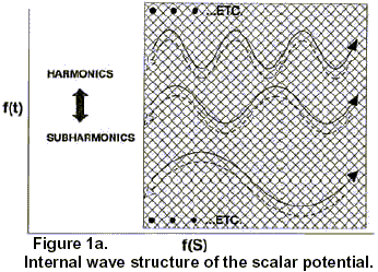
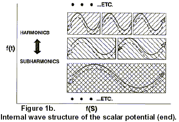
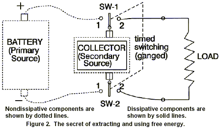
ADDITIONAL COMMENT: March 12, 1993 http://www.cheniere.org
The present classical CEM model prescribes closed, energy-conservative type systems. If any electrical device works totally according to the accepted CEM model, it cannot and will not ever produce overunity. Simply put, you have excluded any hidden EM source that is freely replenished, and you have assumed continual killing of all energy input sources utilized. On the other hand, if one takes the view that the overunity electrical machines are possible after all, then — whether one is consciously aware of it or not — one has implied that classical CEM must somehow be substantially flawed. If it’s flawed, then — being a model — some of its primary assumptions (postulates) and/or fundamental definitions must be in error. The proper place to go after “free electrical energy” is to rigorously examine CEM, over and over, until flaws are uncovered which allow a hidden, freely replenished source of input energy. In other words, one must find a way to “open” the electrical system to an inflow of energy from this source, without closing off the source. Until one finds such an “extension” of CEM, one has no model or concept which can reasonably be expected to provide overunity electrical energy output. Note also that, while the majority of the EM circuitry of an electrical overunity machine may obey CEM, at least one section — where the source is freely tapped and the excess energy extracted — must violate CEM.
I have spent many arduous years in this very process, right or wrong. The bottom line of my search is this: the only verified (by Whittaker and Ziolkowski) (WZ) “freely replenished river” of EM energy, that can act as the required “free energy” source for input to the would-be overunity electrical system, is the potential . But to understand the potential, completely new definitions are required for many entities, among them being energy, electrical charge, electrostatic scalar potential, voltage, etc. The present so-called “definitions” of these entities in CEM are either non-existent, entirely wrong, or quite unsatisfactory.
So far, the search has uncovered two major ways to tap the continually-replenished EM energy in the scalar EM potential:
(1) use of the inner WZ internal biwave structure of the potential as pump waves on/to a nonlinear material (such as the atomic nucleus), so that the nucleus becomes a pumped phase conjugate mirror. Then, by normal phase conjugate optical theory, simply inputting a small signal wave will produce an amplified phase conjugate replica (PCR) wave emitted from the mirror material, and this PCR will precisely backtrack the original input signal wave’s path (see the distortion correction theorem) back out of the nucleus, out of the atom, and into the external circuit. There, the amplified PCR wave can be “filtered off” and sent to the external load, to power the load. The Floyd Sweet vacuum triode works precisely by this mechanism. Note particularly that Barrett has shown that higher topology EM (such as the original quaternion EM theory) can accomplish such “optical functioning” without the use of optical materials.
To do Sweet’s vacuum triode type process is thus theoretically possible with electrical circuitry alone, but one must have more than the current understanding of CEM, as Barrett pointed out. In other words, one can “open” any 4-space system by adding hyperspace (or subspace, if one insists on retaining Minkowski 4-space). One can thus have a hyperspatial source.
Indeed, Ziolkowski and others have already pointed out that the WZ type decomposition of the scalar potential is essentially equivalent to having complex sources.
(2) The second way is to “trap the electron gas electrons” in a separate collector, feed “currentfree potential” to the collector from a primary battery or other source of potential, and collect a bunch of excess energy (potential) in the collector’s “penned up free electron ‘horses'” waiting to carry the excess energy to the load and dissipate it there, once they have been released. Then, one switches the primary potential source away from the collector, while the “energy-loaded horses” are still trapped and straining at the bit, so that no work can be done — by those agitated horses when they stampede out of there — on the internal resistance of the primary source, to destroy or reduce it. In the same switching action, the collector with its “snorting but still trapped electron horses” is switched across the load to form a totally separate circuit with it, having nothing at all to do with the original primary source of potential. Then, the agitated horses are released, and thunder out through the load, scattering their riders (excess energy) in all directions in the load, producing work/heat and powering the load. They will also charge on around to the reverse side of the collector, and kill its charge separation (kill its potential) as well, just as does any ordinary circuit.
The major disadvantage of method 1, as we presently have seen it done (however, check Barrett’s demonstration that Tesla’s patented circuitry is capable of doing it by circuitry alone), is that time-reversed electrical energy is produced. So Method 1 has some serious drawbacks. “Time-reversed energy stuff”, which should stay in the atomic nucleus as Newtonian 3rd law reactions and 3rd-law energy exchanges, is dragged out. Unusual effects on biological systems can occur. Antigravity effects can occur. Other hidden processes in the universes, that affect the atomic nucleus, can be gated into the external circuitry, causing disaster. Monopoles can be deposited in the magnets, causing them to explode like hand grenades. Most of the new “massive time-reverse energy” phenomenology is still unknown. One cannot at this stage of ignorance adequately guarantee human safety. I presently don’t see just how this kind of energy can pass an Underwriter Laboratories’ testing and certification, until a lot more exhaustive work is done to understand the new phenomenology.
Method 2, however, yields ordinary, garden-variety, positive-time electrical energy. The method presented in the paper is my own discovery. No unusual time-reversed phenomena are involved. It would appear to be eminently practical to produce and certify power units based on Method 2. The phenomenology and risks are the same as for ordinary, time-forward power systems.
Method 2 has another unique characteristic: as a system, all the subsystems are already in the literature and validated. They have just not previously been put together in this fashion. So development of the system really represents an “integration” problem only, after one first does a little development of a proper degenerate semiconductor material (DSM). In other words, one first develops (and tests) the exact doping materials and percentage, to get a DSM material that is still a good conductor but has a relaxation time of — say — one tenth of a millisecond. One builds the wires from the battery to the collector out of this new DSM material. If one uses a capacitor for the collector, the plates must be made out of the new DSM material, not out of normal “pure conductor” material. Then one develops a switcher that switches in one tenth (or less) the relaxation time of the DSM, or in this case in one hundredth of a millisecond. That switching time, of course, is easy for any decent electronic technician or electronic engineer.
One also develops a timing circuit that will (1) sense the status of the discharge of the collector energy through the load, and (2) trigger the switching at the correct times so that a smooth twocycle (collect, discharge) process results. Note that the lengths of cycle one and cycle two are not necessarily equal at all. One may use multiple collectors/loads simultaneously, cascaded collectors/loads, etc. Hundreds of variations are possible and feasible.
It is not possible to do anything with this discovery in a normal manner. I would dearly like to be economically independent, so I could work full time in my efforts on free energy, antigravity, extended EM healing, cancer, etc. Many orthodox scientists will also fiercely resist this upstart notion of “overunity” electrical machines to the bitter end. When powerful economic interests realize one has such thing for real , one is certainly going to be stopped, jailed, or killed, or he may just “mysteriously vanish” and never be seen again.
So I just freely released and distributed my discovery of method 2, in the paper “The Final Secret of Free Energy”. It is deliberately targeted toward technicians, junior engineers, and educated laymen. (The principles and definitions raised, however, can be debated to the nth degree by knowledgeable foundation scientists). The paper has already been distributed worldwide. Now the principles and definitions are available to everyone. If they are in error, shortly that will be proven in spades. If they are correct, that will also be established shortly.
Anyone who wishes can develop and patent a particular application. There’s no longer any way to stop this information from being disseminated and utilized. I hope that a flurry of development and patenting activity will result around the world. Get cheap, clean electrical energy to everyone. Bring on the electric auto, clean up the noxious auto exhausts, get rid of giant oil spills, and clean up the biosphere.
Tom Bearden
Additional Information On The Final Secret of Free Energy
Update 15 February 1994, © 1994 by T.E. Bearden
Introduction
My associates and I have filed the first patent application on two electrical overunity processes and devices; one similar to what is outlined in The Final Secret of Free Energy [Ref 1] and an additional variation utilizing, as collectors, standard step-charged capacitors rather than degenerate semiconductor materials. In 60 to 90 days, we will have a very enlightening paper (more likely a book) ready on that. We also plan to file several more extremely fundamental overunity patent applications from additional phenomena and mechanisms that we have uncovered.
In this paper, it is assumed that the reader is familiar with the content of The Final Secret of Free Energy. Figure 1 shows the invention schematically, and we briefly summarize it as follows:
Summary of the Invention
A method and apparatus for extracting bidirectional EM wave energy from the vacuum through the scalar potential gradient across the terminals of an electrical source, collecting the excess energy in a collector without entropy, then separately discharging the collected energy through a load to perform work, without sending the load current back through the primary source against its potential gradient; i.e., against its back emf. Removing the load current from the source thereby substantially reduces the production of work inside the source to dissipate its bipolarity; said internal dissipative work being well-known to be the cause of exhaustion of the source’s ability to continue to furnish emf to the external circuit.
By reduction of its internal dissipation, the source is enabled to furnish more energy for dissipation in the external load than is utilized to dissipate the source internally. Hence the source is enabled to operate with an overunity operational efficiency. The system permissibly operates as an “open” system, and extracts and utilizes excess EM energy from a free-flowing external source (the flux exchange between the surrounding vacuum and the bipolarity of the source), hence it can operate at an efficiency greater than unity without violation of the laws of physics, in a manner analogous to but entirely different from a heat pump. In this invention, it is not the purpose of the primary source to furnish current and dissipative power to the external circuit. The bipolarity of the source is utilized primarily as a dipole antenna to receive the bidirectional EM wave energy flow from the vacuum, and direct it without entropy through a switching unit to the collector. Conduction electrons in the collector are temporarily restrained while being overpotentialized by the excess energy being collected upon them. The collector and its overpotentialized electrons are then switched away from the primary source, and connected across the load as a separate circuit and closed current loop. The electrons in the collector and their excess energy are then automatically released to flow as current discharge through the load, releasing their excess energy to perform useful work in the load. The collector is then switched away from the load and back across the primary source, and another collection cycle is initiated. Iteration of the collection and discharge cycles provides power to the load. Additional collection and smoothing capacitances for smoothing the iterations and furnishing steady power to the load may be added as desired. The invention violates the closed circuit practice of powering loads, but does not violate the conservation of energy law, the second law of thermodynamics, or any of the other known laws of physics.
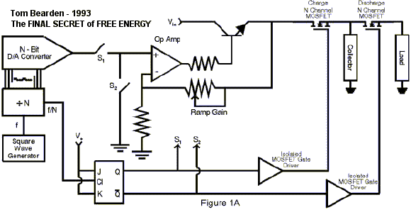
Figure 1a. Type circuit utilized for ramp-up charging of a capacitor without work, and separate discharge of the collected energy in the load without substantial depletion of the primary source.
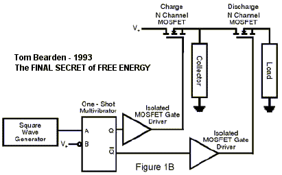
Figure 1b. Type circuit for single pulse charging of a degenerative semiconductor collector without appreciable work, and separate discharge of the collected energy in the load without substantial depletion of the primary source.
Use of Step-Charged Capacitor as the Collector
Fulfilling our search for a special material with the extended electron gas relaxation time for the collector, a material alloy composed of 98% aluminum and 2% iron is tentatively suggested. However, production of this alloy is particularly difficult, so we are still researching for a solution that is more easily manufactured.
Meanwhile, the necessity for using a special material for the collector has been bypassed by another procedure we have utilized. Rigorously one can use a normal capacitor as the collector, if one step-charges it in several hundred small incremental rectangular voltage steps (stair-step-charging). The proof that this can freely charge a capacitor with energy, without having to do appreciable work, is already known in the literature. You can charge the capacitor without entropy and essentially without drawing electron mass current. [Ref 2,Ref 3,Ref 4,Ref 5]
Actually we consider the capacitor to be charged by massless displacement current flow, which for circuitry purposes we consider to be d*/dl — a flow of pure potential (trapped EM energy) along a conductor or through the vacuum; i.e., under conditions where ma s s displacement current flow does not exist. [Ref 6, Ref 7]
Massless Displacement Current Is Freely Available From Any Source
The principle embodied in the invention is that one can extract all the free EM energy one wishes, from any electrical power source, as long as it is extracted via massless displacement current and not by electron mass flow current. [Ref 8] And one can freely collect this extracted energy from a source into an ordinary capacitor if one does it correctly, because one can charge the capacitor via massless displacement current without expending any appreciable work inside the source to dissipate its dipolar separation of charges.
Every Electrical Source of Potential Is Already a Free Energy Source
We thus advance a revolutionary concept: all present power systems already utilize free energy source-antennas. However, the standard two-wire closed circuitry diabolically utilizes one-half the total free energy extracted by the source-antenna from the vacuum, to perform work inside the source-antenna to dissipate its dipolarity and hence to dissipate the source-antenna (i.e. the receiver) itself.
The source already acts as a “dipolar antenna” to continually receive “scalar potential” current d*/dl (massless displacement current) from the vacuum. [Ref 9] Previously scientists and engineers have simply ignored this special massless EM energy influx. For load-free (i.e., mass-current-free) conditions, (d*/dl) is continually received from the vacuum by any dipole (i.e., by any dipolar sou ce-as-an-antenna), and the flowing energy is continually exchanged back and forth between the vacuum and the dipole.
This free energy exchange with the vacuum is also true of any two points in our circuit that possess an open-circuit voltage or potential difference between them. Two such points act as a dipole. Free energy dipolar antenna sources are everywhere; we just have to learn how to break the symmetry in their energy flux exchange with the vacuum, collect some of the freely flowing influx, and distribute that collected excess energy to an isolated load to separately power it.
In other words, we simply have to implement circuitry that operates analogous to the standard heat pump cycle.
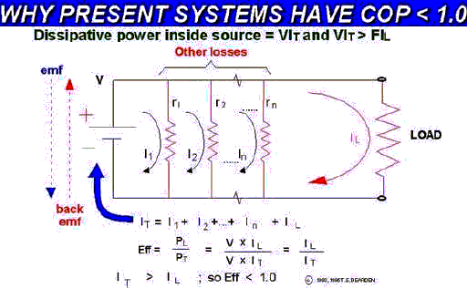
Figure 2. Why present electrical power systems have underunity operational efficiency.
Conventional 2-Wire Closed Circuit Operation
In the conventional 2-wire system a load is added to the source-antenna, allowing circulation of electron current in a closed circuit through the load and then through the ground return line back to and through the dipolar source-antenna. The only useful reasons for this “closed circulation” of the electrons are (1) it is simple, easy, habitual, and accepted, (2) all our components, instruments, and methodologies are developed in accordance with this usage, (3) one uses the electrons as a working material fluid to receive, transport, and discharge excess EM energy, and (4) forcing the electrons back through the back emf reloads the spent electrons again with excess EM energy in the form of little Del*’s (excess trapped energy density) upon each recycled electron.
Some of the excess Del* collected upon the electrons is expended in the load as useful work, but one half of the total is expended in driving the spent (without excess Del* Consequently all conventional 2-wire circuits, which return all external electron-flow current loops back through the source, are always underunity devices, as is shown in Figure 2. Eerily these conventional sources are already free energy devices, which are unwittingly attached to circuitry specifically designed to utilize part of their freely received energy to deplete or destroy themselves, i.e., they are already open systems receiving free energy from the vacuum, but they are hooked up and designed in a suicidal m nner so as to use at least half of that freely extracted energy to re-close the system and shut off the influx of free energy.
Since at least some of the remaining half of the energy is lost in inefficiencies, frictional losses, etc., less than half the total free energy goes to the load. So there is always less useful work being done in the load than the destructive work being done inside the freeenergy source-antenna to destroy it.
Operational Efficiency
We define operational efficiency Alpha as the average power expended in the load to power it, divided by the average power expended inside the source to dissipate its dipolarity. If Alpha 1, then if the additional losses are minimal, the device can conceivably run itself while furnishing some energy to a load to produce useful work.
We Must Excise the Suicidal Closed Circuit To Achieve Overunity
There is no mysticism in the overunity electrical device. The device is an open system that extracts excess energy from the vacuum, collects it, and transports it to the load to separately power the load. It is simply analogous to the standard heat pump cycle. It is also directly analogous to presently operating overunity systems such as windmills, waterwheels, solar cell arrays, and hydraulic turbines in a dam installation. All that we have done is to eliminate or dramatically reduce the standard cancerous mistake in conventional electrical power systems wherein much of the excess energy freely extracted from the vacuum by the already-overunity electrical source is then utilized to destroy the source’s energy reception ability!
As we stated, in the conventional electrical device and circuitry, more destructive work is always done inside the source than is done usefully in the external load. Hence the conventional operational efficiency is always underunity.
Legitimate Overunity Systems Comply With Well-Known Requirements
There are many alternative and well-known permissible free energy systems that operate at overunity operational efficiency: solar cells, windmills, hydraulic turbines, heat pumps, and water wheels, to name a few. All of these are open systems, receiving an influx of free energy from a natural energy flow, and collecting and gating some of that energy to be dissipated in a load to do useful work. All of them are permissible overunity devices, since (1) they are open systems, (2) they constantly receive a free energy influx from an external source, (3) they extract and collect some of this energy without dissipation, (4) they dissipate this collected energy in a load, and (5) the discharge process is totally separated and isolated from the “collection-from-the-source” process.
No Legitimate Overunity System Is Intentionally Made Self-Destructive
Not a single one of these open overunity systems foolishly uses part of its freely extracted and collected energy to re-close the system and shut off its influx of free energy flow!
What engineer would build a solar array such that, the moment the current started to flow, it powered a shutter arrangement to gradually close and shield off the solar array from the sun? Who would build a windmill so that, whenever the angled-blade assembly rotated in the wind to furnish power, a gearing feedback assembly also slowly caused the individual blades to rotate into a position parallel to the wind, thus stopping the windmill?
Yet this is precisely what the conventional electrical power system does with its external circuit. It deliberately utilizes half of the freely extracted energy to re-close the system and shut off the free energy flow between the vacuum and the source-antenna, by destroying the receiver-antenna!
However, this “suicide circuit” practice is guaranteed to keep the power meter on your home or business, and to keep the meter on the gas pump for fueling your automobile.
Perhaps one may be forgiven for suspecting that, at the deepest levels of financial control, this may be the real purpose in seeing that the existing interpretation of classical EM stays “as is.”
All Electrical Power Sources Are Already Free Energy Receiving Antennas
All conventional electrical power systems already contain fully functional free energy systems in their source component. Each conventionally designed system is, however, deliberately suicidal, since part of the system’s own energy is utilized to work against itself and destroy itself. This is primarily due to the preoccupation of engineers with power and work. They do not consider the source as an energy source, but as a power source. Power being the time-rate of performing work, and work being the dissipation of energy, they are thus naturally conditioned to think of the “dissipation of the source” as its natural functioning.
In fact, hardly a single one of them is aware that EM energy itself is a free-flowing process. Only a finite collector possesses a finite collection of EM energy. In nature, the potential gradients of all dipoles are already rivers of free-flowing EM energy exchange with those dipoles, where the energy density is freely furnished and is essentially free for the taking. It is mind-boggling that we have all been conditioned to extract this free energy furnished by nature and the creator, but to always utilize half of the extracted energy to destroy the receiver-antenna and thus strangle the flow!
In our work, we simply have excised this “self-destructive” cancer and reworked the circuitry so that only a minimal amount of the freely extracted energy is utilized for internal destruction of the source-antenna.
Thermodynamics and Open Overunity Systems Not In Equilibrium
In our approach we have an open system during every collection cycle, with an external source of energy and a continual energy influx. We have deliberately broken the local symmetry of the system’s energy exchange with the vacuum, by spatially and temporally separating the energy collection and energy discharge phases. Overunity operational efficiency is permissible for such a system without violation of any of the laws of nature.
Some of the influx of excess energy from the vacuum into the dipolar source antenna is transported without loss to the collector and collected. The collected energy in the collector is then separately discharged through the load, without any of it being discharged back inside the source-antenna. Note that we have broken local energy flow equilibrium but not global energy flow equilibrium.
The second law of thermodynamics, e.g., does not even apply to such an open system not in equilibrium. Classical thermodynamics cannot even compute the entropy of an open system not in thermodynamic equilibrium, as is well-known to thermodynamicists. [Ref 10]
What classical thermodynamics does have to say, is that such an open system must contain excess energy when compared to the closed system in equilibrium, because the closed system in equilibrium is in the maximum entropy condition. [Ref 11] Global conservation of energy is not violated, just as it is not violated in a windmill or in a heat pump, which are similar open systems. Local conservation of energy (which applies only to a closed system or to a system in total equilibrium) does not apply because the system is open and not in equilibrium.
Permissible Electrical Overunity Is Not Perpetual Motion
An open system out of equilibrium need not conform to (1) the local (closed system, equilibrium conditions) conservation of energy nor to (2) the second law of thermodynamics (which assumes equilibrium conditions). It must and does conform to the global conservation of energy, just as does a waterwheel or windmill. We strongly stress that the overunity electrical device is not a “perpetuum mobile.” [Ref 12] The electrical operations and systems we propose are perfectly permissible by the known laws of physics and do not violate any of them. We propose a permissible series of overunity electrical systems.
The Heat Pump Analogy
In one way of viewing it, all we have done is utilize the potential as a more modern type of quantum mechanical fluid having hidden bidirectional flowing EM energy. [Ref 13], Ref 14, Ref 15, Ref 16] QM already certifies that the potentials, not the force fields, are the primary causes of all EM phenomena. Contrary to classical EM theory, the force fields are effects in, on, and of the charged particles themselves. Consequently, if the potentials are the primary causes of all EM phenomena, then for free energy to perform work (free causes to collect and generate desired effects) we must turn to the potentials.
We have utilized a hookup and switching arrangement so that energy-free collection is totally separated from collected energy discharge in the load. In short, we have done what a normal heat pump does, when it uses the air with its thermal energy as a working energycontaining fluid. Consequently, overunity operational efficiency of analogous electrical devices is perfectly permissible, and not prohibited by the known laws of physics.
An Electrical Power Source Is a Dipolar Antenna For Free Reception of Energy
An electrical power source is in fact only a dipolar antenna for reception of potential (hidden bidirectional Whittaker/Ziolkowski waves). All the current you run back through the back emf of the source, to perform dissipative work inside it, is something you yourself are doing to the source. It is not a priori a characteristic of the source!
If no work is done inside the source’s internal bipolar separation of charges (i.e., if no electron or ion current is forced back up from the ground return line against the sourceantenna’s potential and therefore against its back emf), then the dipolar source-antenna will last essentially forever, or until something corrodes or breaks mechanically.
The flow exchange of energy between the vacuum and the dipolar source-antenna is freely driven by all the charges of the universe, in accordance with Puthoff’s cosmological feedback loop. [Ref 17]
Massless Displacement Current
Technically one is using massless displacement current to charge the capacitor, rather than electron mass flow current. It is real energy flow nonetheless; just in work-free, dissipation-free form. As is well-known, one plate of a capacitor already charges the other plate by just this very massless displacement current, transporting real EM energy across the gap between the plates in the process. The electrons themselves do not cross the gap.
Displacement current is already well-known to be “free” energy transport without any dissipation as power and work. By drawing massless displacement current only from the source-antenna instead of electron flow current, you can draw work-free, dissipation-free energy as long as you wish, as often as you wish, and as much as you wish, without ever dissipating the source-antenna. You just have to collect it onto some trapped electrons or other charges, such as in a capacitor’s plates, then switch the collected energy (charged capacitor) separately across a load, in a separate discharge circuit, to discharge through the load as work.
The real trick is to prevent the electrons in the circuit from moving and providing mass “energy dissipation” current inside the source during the collection process. In the original paper, we explained that this could be done by using as a collector a degenerate semiconductor material, with extended electron gas relaxation time. In this paper we have explained how this can be done by step-charging an ordinary capacitor as a collector. We have also included specific references proving (both experimentally and theoretically) that this is correct. With the requirement for special materials removed, there is no reason that a competent researcher cannot develop a step-charged capacitor device to prove it experimentally for himself or herself.
Requirement: Proof of Principle and Independent Test and Certification
My associates and I are proceeding as rapidly as possible toward full-up “proof-ofprinciple” circuits for open release and certification or falsification by the scientific community and engineers at large. Soon we also expect to release to other researcher information on the kinds of new electrical phenomenology one meets in true overunity electrical devices. These are not in the textbook, at least with respect to electrical power systems. We give some indication of these phenomena below:
New Circuit Phenomena Must Be Mastered
One meets unusual electrical phenomena in attempting to perform overunity electrical operations. For overunity, a priori one must “slip excess potential” through the circuit essentially without losses. That is, one must deliberately pass massless displacement currents through the circuit and at least through some of its components.
Solid-state switching components in particular exhibit unusual phenomena, to say the least, when excess potential is introduced into and through all their internal components inside modern semiconductors. An ordinary MOSFET, e.g., may have 25,000 separate internal components. It is as if someone crammed the entire electronic parts store inside it. Simple switches these semiconductors are not, when exposed to appreciable massless displacement current.
When one “slips in” some pure potential, by SWZ decomposition one has also slipped in some bidirectional EM pump waves. The nonlinear semiconductor materials will function as phase conjugate mirrors when suitably pumped, including at non-optical frequencies.
Consequently pumped phase conjugate replicas, self-targeting, formation of quantum potentials, and modular variable effects sometimes begin to evidence. We will address and explain some of these effects in a future paper. For now, we simply state that they occur, and there is a host of extra phenomenology the experimenter may encounter.
However, an iron rule for the experimenter is that, for odd circuit behavior, first exhaust all “normal” causes before turning to the extraordinary causes. One will save oneself a great deal of grief by applying this Occam’s razor.
Also in deliberately utilizing displacement current, one is actually employing an expanded, higher topology EM with additional degrees of freedom, similar to that pointed out by Barrett. [Ref 18] Consequently one encounters a host of additional higher topology EM phenomenology. In particular one encounters nonlinear optical (NLO) functioning of the semiconductors at any and all frequencies, not just in optical bands.
Overunity Electrical Devices Are Permissible By The Laws of Physics
The overunity electrical energy system is permissible by the laws of physics and is not in any manner perpetual motion. It simply extracts excess EM energy from an ubiquitous source, through a dipole as a receiver, and collects that excess energy, conducts it to the load, and separately dissipates it in the load to power the load, without using any of the collected energy to perform work inside the source to dissipate the source-antenna. It is directly analogous to a heat pump, which is well-known to perform at overunity operational efficiency under nominal conditions.
In Conclusion
Primarily my associates and I believe we have corrected an ubiquitous error made in present power systems that prevents these systems from realizing their already-inherent overunity operational efficiency. We also firmly believe that the permissible electrical overunity device is an idea whose time has finally come.
Notes and References
1. T. E. Bearden, “The Final Secret of Free Energy,” distributed over the Internet, Feb. 9, 1993. The paper was also published in Magnets, 7(5), pp. 4-26 (1993); in Explore!, 4(3/4), pp. 112-126 (1993), and in several other media.
2. For proof that you can charge an ordinary capacitor almost without entropy, see I. Fundaun, C. Reese, and H. H. Soonpaa, “Charging a Capacitor,” American Journal of Physics, 60(11), pp. 1047-1048 (1992). A capacitor can be step-charged in small steps to dramatically reduce the entropy required to charge it. In the limit, a theoretically perfect capacitor can be fully charged without any electrical current or work at all, i.e., you can simply transport the excess energy density (the potential gradient) of the open circuit voltage of the source to the collector, and couple that Del* to the electrons trapped in the capacitor plates, without electric current from or through the source.
3. M. G. Calkin and D. Kiang, “Entropy Change and Reversibility,” American Journal of Physics, 51(1), pp. 78-79 (1983).
4. F. Heinrich, “Entropy Change When Charging a Capacitor: A Demonstration Experiment,” American Journal of Physics,54(8), pp. 742-744 (1986).
5. V. K. Gupta, Gauri Shanker, and N.K. Sharma, “Reversibility and Step Processes: An Experiment for the Undergraduate Laboratory,” American Journal of Physics, 52(10), pp. 945-947 (1984).
6. In most texts the treatment of displacement current is far from adequate. A better treatment than most is given by John D. Krauss, Electromagnetics, Fourth Edition, McGraw-Hill, New York, pp. 437-439, 547-549 (1992). Additional useful insight can be gained from David J. Griffiths, Introduction To Electrodynamics, Second Edition, Prentice-Hall, Englewood Cliffs, New Jersey, pp. 304-308 (1989). Problem 7.51 on p. 335 is also of direct interest, as is particularly the comment by Griffiths below the problem. Additional insight can be gained from David Halliday and Robert Resnick, with assistance by John Merrill, Fundamentals of Physics, Extended Third Edition (1988), John Wiley & Sons, New York, vol. 2, Article 37- 4: Displacement Current, pp. 836-837, 839-841. The standard notion is to (1) retain the continuity of current, thus modifying and salvaging Ampere’s law, (2) the displacement current is non-physical, i.e., it does not involve the transfer of charged mass, (3) focus primarily upon magnetostatics as to the results achievable by the displacement current, (4) retain the notion of Del* as E, a force field, thereby focusing the notion of displacement current upon the change of the E field without the flow of charged mass, and (5) retain the confusion between electrical charge and charged mass that is inherent in the terms “charge”, “current”, etc. On p. 836 Halliday and Resnick point out that the displacement current is not derived per se, but is a “fit” based upon symmetry arguments, and it must stand or fall simply on whether or not its predictions agree with experiment. On the same page the displacement current is taken to be a linear function of d*/dt. For flow along a circuit where there is no electron mass current, it seems appropriate to replace d*/dt by d*/dl. It is also strongly indicated that one should clearly distinguish between charged mass current flow and the flow of massless charge, which is the approach we have taken.
A final indication of the way conventional scientists tend to regard displacement current is given by Martin A. Plonus, Applied Electromagnetics, McGraw-Hill, New York, pp. 446-448 (1978). Here Plonus uses the prevailing notion of the E field being altered by the flow of massless displacement current. As can be seen, the displacement current is relegated almost to a curiosity of capacitors, and not really too essential except just to “balance the books” and retain Ampere’s current continuity.
We now wish to point out something very subtle but very rigorous. CEM erroneously uses E = -Del* to equate a mass-free potential gradient with a masscontaining force field. This “E-field” only exists at a point when there is a pointcoulomb of electrical charged mass at the point. The real version of this equation should be E == -[(Del*)*q]/|q|, where Del* is the potential gradient coupled directly to the charged point-mass at the point, q is the number of coulombs of charged mass at the point, q/|q| is one coulomb of charged mass, and E now is properly the force on and of each coulomb of the collected charged mass at the point.
Viewed in this manner, one can now see that the E field may be altered by flow of additional charged mass q, or by flow of massless additional Del*, or both. This is now in agreement with the manner in which it is approached in CEM, but more rigorous. Essentially it states we may increase the total “charge” (potential) at a point by either (1) moving in additional charged masses by use of a conventional current, or (2) moving in additional massless charge (potential) without any additional change in mass, or (3) a combination of the above.
However, let us apply this to a single charged particle or to a fixed number of them.
No one seems to have noticed that the notion of altering the E-field of the collected point- charges at a point via method #2 , i.e. by a flow of massless displacement current onto the fundamental charged particles themselves, a priori requires the electrical charge of each fundamental particle to change. Hence it falsifies the notion of quantization of charge.
Also, no one seems to have noticed the electric power implications: if it is known that one can charge a capacitor purely by displacement current, then one can charge up the capacitor with energy, without any dissipation of the source, because only charged mass current through the back emf of the source does that. So one can then disconnect the charged capacitor and separately connect it in a closed circuit with a load, to discharge through the load and furnish free work in the load (free in the sense than no dissipation of the primary source occurred in either the collection of the energy or in discharge of the collected energy through the load as useful work).
Free energy, overunity electrical devices, etc. should then be readily apparent and permissible, from the known nature of displacement current and capacitors alone.
7. Maxwell assumed a material ether, which was assumed to be a thin material fluid filling all space. Hence force (which must have mass as a component due to its definition F == d(mv)/dt) could be modeled as existing in the Maxwellian ether, for there was already thin matter present everywhere. Hence in Maxwell’s EM the incorrect notion resulted that force fields existed in the vacuum. Oliver Heaviside continued this erroneous assumption, since in fact he hated the potentials, regarded them as mystical, and stated that they should be “…murdered from the theory.”
Also, electricity was thought to be a similar thin material fluid. So the material electric fluid could and did flow through the fluid vacuum also, giving the notion of the material electric flux density for D. Consequently, the units of D are coulombs (charged mass rate of flow) per square meter. Rigorously, that material D flux exists only on and of charged mass that moves; it cannot and does not exist in vacuum. Only potentials and potential gradients exist in vacuum. However, after
Maxwell’s formation of his theory, the Michelson-Morley experiment destroyed the material ether (not the ether per se, but its material nature). So electricians then simply proclaimed that they were no longer using the material ether, and that such did not exist! Not a single Maxwell/Heaviside equation was changed. The material ether is still very much assumed in classical EM (CEM) theory, and so the theory is accordingly very seriously flawed. Since CEM also has no adequate definition for either electric charge or the scalar potential, the problem is confounded.
To clarify this problem, one must separate the notion of electric charge from the notion of mass. The electrical charge of a charged mass is the virtual photon flux exchange between the surrounding vacuum and that mass. Since a virtual photon flux is just a scalar potential, the electron’s massless electrical charge is simply its scalar potential. It can now be seen that, if we forcibly remove the notion of “mass” from D in the vacuum, or in a charged material medium where the charged masses cannot move, then the “material electric flux concept” portion of D turns into d*/dt, a change in the nonmaterial electric flux. However, D is a vector and hence has a “net flux” spatial directional aspect which d*/dt alone does not possess. It follows that the value of d*/dt at a patial point actually represents the result of change of the value of * at that point, as a function of time. Thus a directional operator must first be invoked upon * at the point, to provide a direction for the spatial *-current after the d/dt operator is invoked. The appropriate operator to give directionality to * is Del, so that D in vacuum or in an electron-current-free charged medium becomes a function of d/dt(-Del* ). Conventionally, the use in the literature of E = -Del* immediately provides that d/dt(-Del* ) at a point results in dE/dt, or the time rate of change of the E-field at that point. If no distinction is made between charged mass current flow and massless charge current flow, this would be true in either vacuum or material media. However, we wish to specifically distinguish between massive displacement current and massless displacement current. So we point out that the increase dE/dt in the magnitude of the E-field at, on, and of a charged particle at a point, can be due to either (1) the flow of mass current to build up the number of point coulombs at that given point, where each coulomb has a fixed massless charge (potential), or (2) the flow of massless current d/dt (-Del*) so as to alter the value of at that point, evidenced by a fixed number of coulombs of charged particles, each of which has altered its individual potential and therefore its individual massless electrical charge.
So what “flows” when the charged masses are frozen or absent is simply a current of scalar potential, resulting in a change of the potential upon fixed point charges of d*/dt. This is what crosses between the plates of a capacitor, e.g., which is where the notion of “displacement current” originated in the first place. (See, e.g., Halliday and Resnick, 1988, ibid., p. 836, Sample Problem 1, for expression of the displacement current as d*/dt, neglecting constants of proportionality). This is also what flows when one connects multiple open circuit pairs of conductors to a source.
It remains to examine Maxwell’s equation Del.D = pv. If mass displacement current cannot flow, then there exists no divergence of the mass current portion of D.
However, massless displacement current can still flow, and there can exist divergence of that component. There are now three aspects to that equation: (1) the case in the vacuum, where there exists no physical p and hence no pv as such because of the absence of mass, (2) the case in a material medium, which is the normal case already treated in the standard equation and need not be further addressed, and (3) the case in a material medium where, nonetheless, physical charged masses such as electrons cannot move, but massless charge currents may still move. Only cases 1 and 3 need to be addressed, and they have the same treatment.
We address the one dimensional case, which is sufficient for circuit current flow considerations. First we replace D with (D* + Dp), where the first term is the massless displacement current and the second term is the massive displacement current. In other words, we account separately for charged mass flow and for massless charge flow. Similarly, we express pv as two components, one massive and one massless, so that pv = d/dl( *+ mv). For case 1 and case 3 we make mv = 0 and Dp = 0. For those cases, we have Del.D = Del.D* = d*/dl (since current along a wire is a one-dimensional flow). We specifically note that * , D* , Del.D* , and d*/dl are not necessarily conserved quantities, since * is mathematically decomposed into bidirectional EM waves, and is hence a freely flowing process. When symmetry is broken so that equilibrium conditions no longer exist, one or more of these quantities will not be locally conserved.
What has actually been done here is to open the classical EM model to the free exchange of massless EM energy that is always ongoing between any charged particle’s mass and the vacuum. We then account separately for the flow of the energy exchange (of the massless charge flow) and the flow of the physical receiver/transmitters (i.e., for charged mass flow). Our switching arrangement to separate the collection and discharge cycles constitutes a permissible “Maxwell’s Demon” which breaks symmetry, hence breaks equilibrium and opens the system as required. Since such a system can continually receive a free influx of energy from its external source, such a system can permissibly exhibit overunity operational efficiency without violating the laws of physics.
8. Displacement current is already known to be lossless transport of energy without entropy, i.e., without work. For a typical confirmation see Jed Z. Buchwald, From Maxwell to Microphysics, University of Chicago Press, Chicago and London, p. 44 (1985). Quoting: “…no energy transformation into heat occurs for displacement currents.”
9. We strongly stress again that the scalar potential may be mathematically decomposed into a harmonic series of hidden bidirectional EM wave pairs. Each wave pair consists of an ordinary EM wave together with its superposed phase conjugate replica wave. Thus internally the scalar potential gradient across a source represents a bidirectional exchange of EM wave energy with the surrounding vacuum. See notes 13, 14, 15, and 16 below for references confirming the decomposition of the “fixed” potential into a dynamic flow process and energy exchange process.
10. For confirmation see Robert Bruce Lindsay and Henry Margenau, Foundations of Physics, Dover Publications, New York, pp. 283-287 (1963). See particularly p. 283, which emphasizes that a “field of force” at any point is actually defined only for the case when a unit mass is present at that point. See p. 17 on the limitations of a “natural law”; p. 213 and 215 for limitation of thermodynamic analysis to equilibrium states; and see p. 216 for definition of entropy. See p. 217 for the fact that the entropy for non-equilibrium conditions cannot be computed, and the entropy of a system not in equilibrium must be less than the entropy of the system in equilibrium, i.e., for a system to depart from equilibrium conditions, its entropy must decrease. Therefore its energy must increase. Thus the energy of an open system not in equilibrium must always be greater than the energy of the same system when it is closed and in equilibrium, since the equilibrium state is the state of maximum entropy.
11. Lindsay and Margenau, ibid., p. 217.
12. The basic notion in the perpetual motion conundrum is that somehow a closed system in thermodynamic equilibrium could perpetually provide external energy to a load outside the system. Such a notion is an oxymoron; if the system is closed, no energy can escape or enter, hence the system could not furnish energy externally to power a load or even just to radiate away. My associates and I have not in any manner proposed such a system or entertained the notion that such might exist. But it is well-known that open systems not in thermodynamic equilibrium can freely extract energy from their environment and furnish energy to power a load, and that is precisely what we have proposed.
13. G. J. Stoney, “XLVIII. On a Supposed Proof of a Theorem in Wave-motion, To the Editors of the Philosophical Magazine,” Philosophical Magazine, 5(43), pp. 368- 373 (1897).
14. E. T. Whittaker, “On the Partial Differential Equations of Mathematical Physics,” Mathematische Annalen, vol. 57, pp. 333-355 (1903). Whittaker mathematically decomposes the scalar potential into a bidirectional series of EM wave pairs in a harmonic sequence. Each wave pair consists of the wave and its phase conjugate. (We have pointed out elsewhere that such a wave pair is a standing electrogravitational wave and a standing wave in the curvature of local space-time).
To see that all classical EM can be replaced by interference of two such scalar potentials (i.e., by the interference of their hidden multi-wave sets), see E. T. Whittaker, “On an Expression of the Electromagnetic Field Due to Electrons by Means of Two Scalar Potential Functions,” Proceedings of the London Mathematical Society, Series 2, vol. 1, pp. 367-372 (1904).
15. Richard W. Ziolkowski, “Localized Transmission of Electromagnetic Energy,” Physical Review A, 39, p. 2005 (1989). For related material, see Richard W. Ziolkowski, “Exact Solutions of the Wave Equation With Complex Source Locations,” Journal of Mathematical Physics, 26, pp. 861-863 (1985). See also Michael K. Tippett and Richard Ziolkowski, “A Bidirectional Wave Transformation of the Cold Plasma Equations,” Journal of Mathematical Physics, 32(2), pp. 488-492 (1991).
16. C. W. Hsue, “A DC Voltage is Equivalent to Two Traveling Waves on a Lossless, Nonuniform Transmission Line,” IEEE Microwave and Guided Wave Letters, 3, pp. 82-84 (1993).
17. H. E. Puthoff, “Source of Vacuum Electromagnetic Zero-point Energy,” Physical Review A, 40(9), pp. 4857-4862 (1989). Presents Puthoff’s self-regenerating cosmological feedback cycle for the source of the vacuum EM zero-point energy. Our comment: Over any macroscopic range, the vacuum fluctuations (Del*’s) of the ZPE sum to a vector zero translational resultant. The individual ZPE components ( Del*’s), however, are still present and active, and their energies are present as well.
That vector zero can thus be considered to be a gradient-free potential, or the vacuum potential, since it contains enormously dense, trapped EM energy. So the vacuum potential — pure space-time (ST) itself — contains enormously dense EM energy.
One can then apply the Stoney/Whittaker/Ziolkowski (SWZ) methodology to decompose this powerful vacuum potential, i.e., the vacuum, and in fact space-time (ST) itself, into an incredibly dense flux of EM energy. Space-time is revealed to be an incredibly powerful electrostatic scalar potential. The electrical charge (potential) of a charged particle is a small potential gradient in the ST potential, i.e., it is a slight alteration of the local ST potential. Via Puthoff’s self-regenerative feedback cycle, the energy flowing in this potential is being exchanged between the local source and all the charges everywhere in the universe. This “potential gradient” or electrical charge itself can be decomposed via the SWZ approach, and becomes a bidirectional EM wave pair exchange of excess EM energy between the vacuum/ST and the charged particle’s mass. The potential gradient between the ends of a dipole have similar decompositions, with the additional characteristic that the negatively charged end of the dipole receives the forward-time waves from the SWZ wave pairs, and the positively charged end receives the time-reversed waves.
Our final comment is that Cole and Puthoff have rigorously shown that, in theory, the vacuum EM energy can indeed be extracted. See Daniel C. Cole, and Harold E. Puthoff, “Extracting Energy and Heat from the Vacuum,” Physical Review E, 48(2), pp. 1562-1565 (1993).
18. T. W. Barrett, “Tesla’s Nonlinear Oscillator-Shuttle-Circuit (OSC) Theory,” Annales de la Fondation Louis de Broglie, 16(1), pp. 23-41 (1991). Barrett shows that a higher topology EM model (e.g., EM expressed in quaternions) allows shuttling and storage of potentials in circuits, and also allows additional EM functioning of a circuit that a conventional EM analysis cannot reveal. As an example, one may meet optical functioning without the presence of optical materials.
LEGEND:
* = filled black dot (like scalar product) in original text
# = Greek letter # for the Scalar Electrostatic Potential field
$ = Greek letter Nabla (upside down triangle)
|x| = Absolute value of x (only positive)
uf = microFarad
PRACTICAL OVERUNITY ELECTRICAL DEVICES, (C) T.E. Bearden, May 13, 1994
Introduction
Recently, my associates and I have filed a patent application on what we believe will at long last reveal the mechanisms for practical overunity electrical devices. It is my purpose in this paper to provide additional information augmenting my former two papers, (1) “The Final Secret of Free Energy,” Feb. 1993, and (2) “Additional Information on the Final Secret of Free Energy,” Feb. 1994. In this present paper, with the permission of my colleagues, I release the gist of our work on separation of electrical charge into two coupled components #* (m), where #* represents the massless charge of the charged particle or mass, * represents the fact that it is coupled or trying to couple to the special mass that makes up charged particles [i.e., the special kind of mass that will couple to the virtual photon flux density that is represented by the symbol #], and m represents the inert mass component of the charged mass. Since not all masses will couple with #* , we indicate the type of mass that will couple with it, as *m. Thus a charged mass is composed of (# *)* (* m), which we consolidate to (#) *(m).
Charge Is Not Quantized
An interesting immediate result is that the massless charge of a fundamental charged particle is not quantized; it changes as a function of the background potential in which it is embedded. So it is discretized as a function of the background potential (i.e., of the virtual photon flux exchange between it and the surrounding vacuum). Otherwise, e.g., there could be no $# created on any charged particle q, and hence no E-field, and hence electrons would not move in our present circuits. Since they do move in our circuits, charge is not quantized.
Electrical Current Has Two Components
The first key to understanding free energy electrical and magnetic machines is to realize that electrical current actually consists of two currents coupled together. Our treatment of an electric charge as a coupled system (#)*(m) also means that electron current i = dq/dt is comprised of two coupled components [(d#/dt)*(dm/dt)]. This follows from simply invoking the operator d/dt; i. e., d/dt[(#)*(m)] = (d#/dt)*(dm/dt), which is the same as [(d#/dt )*( dm/dt)]. The component (d#/dt)* is the known but not well understood massless displacement current, while the component *(dm/dt) is the mass displacement current, and the coupling operator* means “coupled to” or “trying to couple to”. The coupling operator represents a real physical operation: the exchange of virtual photons between the vacuum potential and the charged mass. Any potential #1* is considered to be a potential that is superposed upon the ambient vacuum potential #0* , to provide a potential (#0+#1)* . The ambient vacuum potential does not disappear merely because we add another potential to it!
Confusion In Present Electrical Physics
We point out that, in physics books of note, the overt coupling effect is essentially unknown or ignored because physics presently has not defined either the scalar potential or the electrical charge. The conventional theory simply uses an “inert” expression d#/dt to represent the displacement current (and another inert expression q for a charged mass), and most theoreticians are uncomfortable even with that. The displacement current is also confused with force by equating the displacement current d#/dt to dE/dt. In turn, this means that d#/dt is confused with mass, hence with dm/dt, which latter is also a component of dq/dt. m is always an internal component of force, as is known in foundations of physics but this fact continues to remain completely oblivious to the electricians. [Good electrical theorists do admit that there is no force in the vacuum; and that the force associated with the E-field is evidenced only in the interacting mass. However, they continue to maintain the E-field (force per point-coulomb of charged mass) in the vacuum, when there are no point-coulombs of charged mass there!
Mass Is an Internal Component of Force
It is easy to show that mass is always a component of force: We will simply define force precisely. We first insist that no equation can be used as a definition; an equation simply states that the magnitude of one of its sides and the magnitude of the other side are equal. (The length of a board and the length of a human may be equal, but writing that as an equation has absolutely nothing to do with the definition of either a board or a human). So we will insist that any true definition must be an identity.
We define force F as F == d/dt(mv), whereupon mass is a component of force a priori. It follows that, if we define the E-field E as the force per coulomb, we are defining it as the force existing at a point and having a point-coulomb of charged mass as one of its major components. We may accurately now define E as E ==-[($#)*(q)]/|q|, where the absolute value symbol in the denominator is essential, q/|q| being one point-coulomb. [We leave as an exercise for the reader the further reduction of this definition by treating q as *(#*m)].
At any rate, with the new and correct definition of the E-field, one can see that the flow of displacement current (d#/dt) upon a collector such as a rigid capacitor, containing a fixed charge *(#*m), will result in the formation of an excess $#* upon those restrained charges in the capacitor plate, so that there is created an E ==-[($#)*(q)]/|q|. Since the conventional theory considers the antigradient of the potential as an E-field, then one can now see the exact mechanism that creates this E-field that grows upon the capacitor (across its plates) as it charges. In fact, the q/|q| cannot change in a capacitor if its plates and dielectric are immovable.
Instead, in that case, the #* portion of the trapped *(q) changes, producing the ($#)* change. Since the ($#)* component is coupled to the mass component of the fixed *q as (#+$#)*m, then an E-field is created and exists as E ==-[($#)*(q)]/|q|.
An Ideal Capacitor Is an Electron Current Blocker
We point out that, if the capacitor’s components are ideal, completely rigid, and do not physically move, then the capacitor is a “*dm/ dt blocker.” If the charges really were frozen in place, then the potential would flow across the plates at the speed of light, via the flow of excess massless displacement current d#/dt* . In that case, an ammeter would not show the classical “exponential fall-off” of the current with time; the electron current dq/dt would occur as a single-point Dirac delta function at t=0, and would be zero thereafter.
And no electrons would be able to move in zero time. The voltage would show an instantaneous adjustment to the charged value with a single step-function, and the capacitor would charge up fully, instantly, with no work (energy loss) whatsoever being done. And this charge-up of the capacitor would not dissipate in the slightest the source furnishing the voltage; there would be no electron current dq/ dt through the back EMF of the source, hence no work inside it to deplete its separation of charges.
Problems With Ordinary Capacitors
However, most ordinary capacitors are much more than just an ideal capacitor. The plates move, the dielectric moves, etc. due to the forces created upon them by the E-fields created upon the trapped charges in them. The spatial translation of the resulting force moving the plates constitutes work; i.e., it dissipates some of the flowing d#/dt energy. Each movement of the plates and/or dielectric carries with it all its internally trapped charges. The movement of those charges constitutes a substantial longitudinal electron current dq/dt, when compared to the longitudinal “drift” electron current in normal circuits. [Electrons spend most of their time moving radially in a wire, not down it.] This “moving plate and its transported charges” make an electron current, which pumps the inert electrons in the ground return line back through the back EMF of the source, depleting the source. Consequently, the ordinary capacitor will simply release as much energy as work (to move the plates and dielectric) as it stored. Hence, it will also produce dissipation of the source via the amount of energy stored in the capacitor. You still get “free energy” stored in the capacitor, but also dissipate the source by an equal amount.
Rigidized Capacitors Must Be Used
Only rigidized capacitive collectors are useful in free energy devices. Such capacitors are in fact actually available, e.g., as calibration standards, but they are extremely expensive (USD400 to USD2,000 or so each, for a capacitance reaching about 1 uf).
So, capacitive type collectors must be rigidized, if used in overunity circuitry. Even so, in a single integrated circuit, although one collects free energy, one will use half of what was collected to dissipate the source. Not all the remaining half will be discharged through the load; some will be discharged in other circuit and component losses. Hence, there will always be less work done in the load than is done in the source to kill it, by a conventional two wire single closed circuit. In my second referenced paper (Feb.94), I included precise proof that this is true. One must use energy collection and shuttling between two isolated circuits, and the load discharge current must not pass back through the primary source of potential.
We have previously provided precisely how to utilize capacitive collectors in our two referenced papers. We point out here that the capacitors must be calibration standard capacitors, or specially made rigidized capacitors.
It Does Not Require Electron Current to Charge An Ideal Capacitor
For the benefit of the skeptic, this is already proven. We simply list references (2) and point out the equation that represents the energy K in a charged capacitor. Here we have K = ½(CV)2. It is totally the displacement current d#/dt* flowing (from a higher potential) onto the charging plate that produces the higher potential # on that charging plate, and hence a V between the two plates, one of them (the “ground” side) being held at a constant potential. The mass displacement current component dm/dt of the electron current dq/dt has nothing whatsoever to do with energy accumulation; it has only to do with the dissipation of energy that is happening simultaneously in all losses and loads in the circuit loop.
We reiterate that most ordinary capacitors have terrible internal movement, and accomplish as much energy dissipation as they do energy collection by permitting dq/dt and work performed upon the plates and dielectric to move them. The standard two-wire circuit also guarantees that all such dq/dt current “through” the capacitor is passed back through the source against its back EMF, doing an equal amount of work in the source to dissipate its separation of charges and “destroy” the source.
An ideal capacitor does not pass dq/dt, but only massless displacement current as theorized by Maxwell to save current continuity in a circuit containing a capacitor, and hence to save Ampere’s current law. That is, an ideal capacitor is a *dm/dt blocking device.
However, the capacitors utilized in normal circuits are not ideal capacitors at all. By allowing the plates to move, electron current dq/ dt is created on both sides of the capacitor. Otherwise there would not be a ground return dq/dt, but only a ground return d#/dt* .
This d#/dt* would not and does not push electrons back up through the source against its back EMF; else the ground side of the source, which is engaged in continuous d#/dt* exchanges with the vacuum, would produce destructive amperage d#/dt* in the battery or potentialized source, against its back EMF, while it was simply sitting on the shelf. In fact, a flow of d#/dt* continually runs from the vacuum to the positive terminal, then through the inside of the battery to the negative terminal, and thence back to the surrounding vacuum. Also, the incoming flow from the vacuum “splits” at the positive terminal, where one branch flows inside the source to the negative terminal, and the other branch flows through the external circuit to the ground return line, and thence to negative terminal and back to the vacuum. In the external circuit, the d#/dt* hooks to free electrons and moves them as ordinary dq/ dt. In the internal circuit inside the source, the electrons are restrained, hence they only move when their restraint is overcome.
Displacement Current d#/dt Is Real
In recent years, SQUID detectors have been utilized to detect the magnetic field created between the plates (at right angles) by the displacement current d#/dt between the plates, providing strong evidence that displacement current is physically real. The best proof that it is real is a charge blocking device, two isolated circuits using energy collection and shuttling, and overunity powering of loads in the secondary circuit.
A Problem With Ammeters and Measurement of d#/dt
Note that an ammeter cannot differentiate between displacement current d#/dt* and normal current dq/dt. In the ammeter, the sample d#/dt* will couple to free electrons, producing a normal dq/dt inside the ammeter. The driving of this dq/dt through a precision resistance, e.g., is measured and the instrument is calibrated to show the dq/dt amperes flowing. One of the major needs of free energy researchers is the development of a good current meter that will differentiate between d#/dt* and dq/dt, and measure each one. Short of using a mass spectrometer to differentiate the mass current *dm/dt, and comparison of those mass current measurements with an ammeter’s measurements of the “current” dq/dt, and calculating the d#/dt* from that, I presently know of no way to precisely and simply measure and separate the two current components. I have been thinking of utilizing a multi-channel sampling meter set arrangement, where one channel uses a *dm/dt blocking device such as the Fogal semiconductor in this respect, but have not yet developed the complete concept.
Better Solution: A Charge Blocking Device
A better solution than the capacitor or capacitive collector is the use of a special rigid solid state “charge blocking device”, such as a Fogal semiconductor, to enable the current separation into two components, blocking of the mass flow component, and passage of the massless displacement current component. In overunity electrical devices, it is massless displacement current d#/dt* that must be separately passed down the primary circuit and collected in the collector as an E-field or an H-field. This provides “free” energy that has been extracted from the vacuum, via the potential difference between the terminals of the source antenna, and collected and stored in the appropriate field, without work. The collected free energy may then be transferred to the isolated load circuit by a variety of means, for separate discharge through the load without return of dq/dt through the source.
The Fogal Semiconductor Meets the Charge-Blocking Requirements
Fogal’s marvelous semiconductor blocks passage of electrons into its output terminal, but passes displacement current d#/dt* into it.
The semiconductor is powered by (receives) normal electron current and excess d#/dt* , but outputs pure massless displacement current d#/dt* . A charge blocker that passes d#/dt* is ideal for our overunity mechanisms, enabling them to be readily obtained as we shall shortly see.
Energy, Flow, Finite Amount of Energy, and Collectors
We accent that the flow of energy in an electrical circuit is purely by means of the massless displacement current component (d#/dt)*. The flow of the mass component *(dm/dt) represents the “flow of work” (energy dissipation) in the circuit. Power is rigorously the time rate of doing work, and electron current dq/dt is a part of power. It has nothing whatsoever to do with the time rate at which energy is transported without loss; instead, power represents the rate at which energy “leaks” or is “lost” during its transport.
All measurement is work, not energy. Energy cannot be measured, even in theory, a priori. Energy is also a flow process, and never a finite amount in one location. A specific differential of energy flow may exist on a specific finite collector. However, it only represents a certain constant differential amount of energy flow compared to the universal vacuum energy flow or some other flow reference point. It is like a whirlpool in the river. Energy is like the flowing water, and an “amount” of energy is like the amount of water in the collecting whirlpool form (between its input flow and its output flow) at any time. Obviously, energy (ordering) forms can come and go; the water flow itself remains. Any “magnitude of energy” is always a “trapped” amount of energy in a “collector” (form).
Decoupling Current Components and Utilizing d#/dt
The two components of electron current dq/dt can be decoupled, by blocking the *dm/dt component while allowing the d#/dt* displacement current to continue to flow. In our first paper, we pointed out one way: utilizing a special degenerate semiconductor material whose electron gas relaxation time is extended, providing a finite time during which the material serves as a charge (i.e., a charged particle) blocking device, while passing the flow of potential (the d#/dt* massless displacement current component) and restraining the mass displacement current component *dm/dt. With the advent of Fogal’s semiconductor, the process becomes much easier to obtain and utilize in practical machines and circuits.
In our second paper, we pointed out a second way: utilize an ordinary capacitor and ramp-up step-charging. We found, however, that in most ordinary capacitors, the capacitive aspect is defeated by the sloppy movement of the plates and dielectric, converting d#/dt* into dq/dt. Only a few very carefully selected capacitors are sufficiently rigid and can provide overunity. One must use rigidized calibration standard capacitors for the ramp-charging by series steps method to be successful. With ordinary capacitors, however, one can readily demonstrate that the efficiency can approach 1.0 rather than 0.50 as expected.
Overunity Secrets: Charge Blocking, Collection, Shuttling, and Two Isolated Circuits
The charge (actually charged mass) blocking approach provides a massless, free flow of vacuum EM energy that can be directed to a collector (capacitive or inductive) where it can be stored in either an E-field or a B-field. This stored energy can then be transferred to an isolated load circuit whose electrons (and hence their *dm/dt mass displacement current) are free to flow as dq/dt. In the isolated load circuit, then, the two components [(d#/dt)*(dm/dt)] again couple to form i = dq/dt = [(d#/dt)*(dm/dt)], powering the load. All work in an electrical circuit is due to the mass displacement current *dm/dt component; the massless displacement current (d#/dt)* is a flow of pure energy transport without loss, as is well-known. (For example, see Reference 4.)
Therefore, the first major free energy secret is simply to block the “working” component *dm/dt of the current dq/dt while allowing the excess “lossless energy flow” component d#/dt* to flow to collectors to produce either free E-field or free B-field thereupon.
The second major secret is to transfer the collected excess free energy (via energy shuttling) to a second, isolated, load circuit, where the energy is discharged through the load in the conventional fashion (i.e., such that the two current components are coupled, and electron current i = dq/dt occurs through the load). The second circuit must be isolated from the original collection circuit, so that none of the load electron current dq/dt passes back through the original source, against its back EMF.
Should the grounds be the same between the load circuit and the collection circuit so that load electron current is returned through the back EMF of the primary source, then exactly as much excess work will be done inside the source to dissipate its separation of charges as was done in the external load to furnish useful work and in the external losses. In that case, overunity is destroyed, because one is using one-half the excess free energy to destroy the source faster, while the remaining half is distributed among all external loads and losses. Since there are always some external losses besides the load, then the ratio of load power to source dissipation power is always less than unity in a conventional closed-loop circuit containing both load and source. Hence the necessity for utilizing two isolated circuits: one where energy is collected freely from the source, and one where energy is dissipated as work in the load without dissipative work in the source, and energy shuttling between them.
A Simple Open-Loop Overunity Device
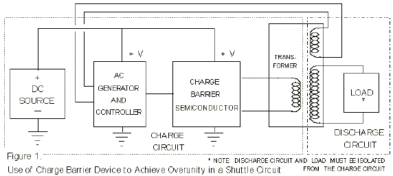
Figure 1 shows a very simple but very powerfully amplified overunity device, using an AC charge blocking semiconductor (CBS) (such as a Fogal semiconductor). The gist of the circuit is that an AC source furnishes AC current dq/dt to the CBS, which uses some of the power to power itself, but then blocks the *dm/dt portion of the dq/dt input current, passing only the massless displacement current component (d#/dt*) into its output circuit. The (d#/dt*) output of the CBS is fed through the primary winding of a transformer, in this case a step-up transformer. The “current gain” of the CBS will depend upon (1) the load connected to it, and (2) the ability of the CBS to continue to block the increasing E-field on its trapped charges, as more free energy flow (d#/dt*) is drawn through it by the load. Thus the load and the CBS must be matched within the operational ability of the CBS, so that the CBS does not fail catastrophically.
In the primary winding of the transformer, the (d#/dt*) displacement current produces a magnetic field H, storing the excess flowing energy in that field. This is a normal magnetic field; all magnetic fields are produced by the (d#/dt ) component of the current anyway. This magnetic field, as it changes, couples to the secondary winding, producing a normal magnetic field H therein by normal means. In the secondary circuit, electrons are not restrained by a CBS. Hence the (d#/dt*) induced in the circuit on the secondary side couples to the unrestrained electrons, producing normal electron current dq/dt, and driving it through the load to power it. Note that energy is conserved across the primary and the secondary; however, dissipative power and work (energy loss rate and energy loss) are not conserved, because a free flow of lossless excess energy in the form of displacement current is flowing from the vacuum through the source antenna, thence to the CBS, through it to the primary of the transformer and into the primary magnetic field, through it to the secondary magnetic field, through it into the (d#/dt*) induced in the secondary circuit and coupled to the electrons, through the resulting dq/dt into the load, where the scattering of photons as heat dissipates the free flowing energy in the displacement current d#/dt* component flowing through the load as a component of dq/dt = (d#/dt*)*(*dm/dt) = (d#/dt)*(dm/dt).
Free “Power” Amplification
If one places an ammeter in the output from the CBS, between it and the primary winding of the step-up transformer, one will read the (d#/dt*) as normal dq/dt in the ammeter itself. If one calculates the “free power” (i.e., the rate of energy dissipation) that is going into the transformer primary using this as the “current,” one will show that energy and “power” are conserved between primary and secondary of the transformer. However, the actual dissipative power going into the primary side is zero or, in real circuits, vanishingly small. Consequently, the device has a very high variable power gain that depends upon the rate of energy draw and dissipation of the load on the secondary side. If one adds more load, one draws more dq/dt current on the secondary side, hence more excess d#/dt* displacement current on the primary side. The overall “power amplification” is limited by the ability of the transformer to handle the power in the secondary and the ability of the CBS to withstand the pressure of the internal charge barrier.
This device can be easily “close-looped.”
The Negative Resistor: A Close-Looped “CBS and Shuttle” System
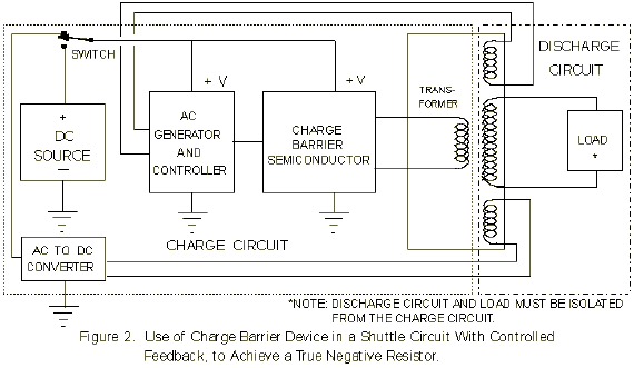
Figure 2 shows the close-looping of the device shown in Figure 1, in such manner that, once stable operation is underway and the load and input stabilized, the ordinary power supply for the CBS can be switched out of the circuit. In this case, the circuit operates as a self-powered overunity device; i.e., as a negative resistor.
A normal resistor receives an ordered energy flow from its external circuit and scatters this energy as work out to the vacuum. I.e., it receives i = (#+$#)/dt* (dm/dt) (scatters the excess ($#)/dt* component (i.e., of the dq/dt passing into it from the high potential side) by radiating it away to the surrounding vacuum as scattered photons (heat)), and outputs inert (no excess ($#)* component) electron current dq/dt into the ground side.
A negative resistor does exactly the opposite: it accepts inert incoming electrons from its “ground” side, also accepts incoming (converging) d#/dt* energy from the vacuum as virtual photons being absorbed upon these inert electrons so that a $#* is added to the electron current, creating an excited, excess energy-carrying i = (#+$#)/dt* (dm/dt), and passes this excited current out of its high side and out into the external circuit to power the circuit. In other words, the negative resistor becomes a self-contained free power source, once brought up to stable operation.
In Figure 1, all that needs to be done is simply to extract some of the secondary power and feed it back to create the power input consumed by the CBS and the other normal components of the primary circuit side of the transformer.
Multitaps can be added to the secondary side, to provide varying voltage power supplies for loads requiring different voltages.
Energy is conserved in the device, because it always functions as an open circuit, receiving excess energy from an external source (the surrounding vacuum, in its virtual photon exchange with the charges in the system). It is far from thermodynamic equilibrium, and classical thermodynamics (including the second law) does not apply.
It is simply a continuous free power supply: it is a negative resistor.
Far more complicated units can be designed and produced. The basic point is that this type of overunity power supply is continuous and self-powered, driven by the violent exchange of energy from the vacuum, and simply collecting and gating some of that energy to the load to power the load.
Conclusion
With this third paper, we complete the triad of papers we set out to write a little over a year ago. With the availability of charge barrier devices such as the Fogal semiconductor, together with the collection, shuttling, and use of free d#/dt* flowing energy, the Age of Free, Clean, Electrical Energy has finally dawned.
Let us use it wisely, and for the betterment of humankind, not for its destruction.
[Support of portions of this research by A.D.A.S. is gratefully acknowledged.]
References and Notes
1. Bearden, T.E., Feb. 9, 1993, “The Final Secret of Free Energy,” ADAS, distributed over Internet. The paper was also published in Magnets, 7(5), May 1993, p.4-26, in Explore!, 4(3/4), 1993, p.112-126, and in several other media. See also Bearden, T.E., “Additional Information on the Final Secret of Free Energy,” Feb. 15, 1994, distributed on Internet.
2. For proof that an ordinary capacitor can be charged almost without entropy, see Fundaun, I., C. Reese, and H.H. Soonpaa, “Charging a Capacitor,” American Journal of Physics, 60(11),Nov. 1992, p.1047-1048. See also Calkin, M.G. and D. Kiang, “Entropy change and reversibility,” American Journal of Physics, 51(1), Jan. 1983, p.78-79. See also Heinrich, F., “Entropy change when charging a capacitor: A demonstration experiment,” American Journal of Physics, 54(8), Aug. 1986, p.742-744. See also Gupta, V.K., Gauri Shanker, and N.K. Sharma, “Reversibility and step processes: An experiment for the undergraduate laboratory,” American Journal of Physics, 52(10), Oct. 1984, p.945-947.
3. In most texts, the treatment of displacement current is far from adequate. A better treatment than most is given by Krauss, John D., Electromagnetics, Fourth Edition, McGraw-Hill, New York, p.437-439, 547-549. This treatment must still be augmented by treatment from other texts, and the ensemble “synthesized.” Even then, it will never be completely clear until the separation of mass from the massless charge, and separate accounting of the two, is accomplished in the manner pointed out by the present paper.
4. For a typical confirmation that massless displacement current is already known to be lossless transport of energy without entropy, i.e., without work, see Buchwald, Jed Z., From Maxwell to Microphysics, University of Chicago Press, Chicago and London, 1985, p.44. Quoting: “…no energy transformation into heat occurs for displacement currents.” It should be obvious from this fact alone that the proper way to accomplish overunity in electrical devices is to utilize the massless displacement current to flow and store excess energy, then use a “heat pump” type cycle to transfer the collected energy to a separate load circuit and discharge it separately in the load.
5. For a very recent proof that the potential is a flow process, and in fact consists of bidirectional EM waves, see Hsue, C.W., “A DC Voltage is Equivalent to Two Traveling Waves on a Lossless, Nonuniform Transmission Line,” IEEE Microwave and Guided Wave Letters, 1993, Vol. 3, p.82-84.
6. For proof that the vacuum EM zero-point energy is continually produced by a cosmological feedback from every charged particle in the universe, see Puthoff, H.E. , “Source of Vacuum Electromagnetic Zero-point Energy,” Physical Review A, 40 (9), Nov. 1, 1989, p.4857-4862.
7. For proof that in theory the vacuum energy can be tapped, see Cole, daniel C. and Harold E. Puthoff, “Extracting Energy and Heat from the Vacuum,” Physical Review E, Vol. 48, No. 2, Aug. 1993, p.1562-1565.
8. For proof that a higher topology examination of EM phenomena allows energy collection as potentials and energy shuttling in circuits, see Barrett, T.W., Annales de la Fondation Louis de Broglie, Vol.16, No. 1, 1991, p.23-41. Barrett shows that EM expressed in quaternions allows shuttling and storage of potentials in circuits, and also allows additional EM functioning of a circuit that a conventional EM analysis cannot reveal. He in fact shows that Tesla’s patented circuits did exactly this.
9. Stoney, G.J. (1897) “XLVII. On a Supposed Proof of a Theorem in Wave Motion, To the Editors of the Philosophical Magazine,” Philosophical Magazine, 5(43), 1897, p.368-373. Stoney first pointed out the bidirectional EM wave decomposition of the scalar potential.
10. Whittaker, E.T., “On the Partial Differential Equations of Mathematical Physics,” Mathematische Annalen, Vol. 57, 1903, p.333- 355; “On an Expression of the Electromagnetic Field Due to Electrons by Means of Two Scalar Potential Functions,” Proceedings of the London Mathematical Society, Series 2, Vol.1, 1904, p.367-372.