## About the CONSTRUCTION of a JOECELL:
Walter Russel’s orgone generator:

Diagrams of JoeCells:
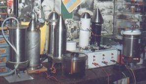
High voltagesystems with water:
(to link the article above use: #PICS)
## CELL PROBLEMS: http://rexresearch.com/joecell/joecell1.htm
PIN-POINTING THE PROBLEM; originaly from www.joecell.com/au 12-12-2001
As this paper is headed Cell Problems , I will not cover problems in the transfer stages or the modifications required to the consuming device. I will concentrate on the cell only.
The above title is somewhat of a misnomer as I will describe how to make a stage 3 cell. If you do not follow the instructions, then you can pin point the problem to the step that you did not follow.
I am telling you what I know will work. If you decide to take short cuts with my suggestions, fine, but dont come to me when your cell doesnt work!
In the following sub-headings I have covered the locations where the problem may reside and I have suggested various options.
Location — Strictly not cell related, so see my manual ; The individual — As above ; Cylinders and case material — As we are employing electrolysis, it would be logical to employ a material that is largely immune to the actions of the electrolysis process. After many tests, and including Joes recommendations, stainless steel is the logical choice. All other material like copper, brass and aluminium are interactive.
Joe has suggested food grade non-magnetic steel as the right one. This advice is a little nebulous, but it points us to the 300 series of stainless steels and logically the choice is out of 304, 316 and 316L.
The dairy industry in Australia ( this is where Joe obtained his steel ) uses 304. Lately Joe has suggested 316 non-magnetic, food grade.
I personally have found very good results with 316L. I would suggest to you that 304 or 316 are both fine, the points that are important is the non-magnetic aspects of the material and the neutrality to electrolysis.
The next stage is to find the stainless and make sure that we buy the correct type. Where I am, I can simply go for a 20 mile drive and this will allow me to have a scrounge at several scrap metal dealers. Of course you may not be so lucky, you may have to buy it new, ouch.
A couple of years ago, I was involved in the testing of all possible stainless steels for a potential mass producer of the cell for the world market. Now this was a chance of a life time for me as I did not have to pay the many thousands of dollars that were required to purchase a length of each type ( including 316S designed for the nuclear industry, very beautiful material indeed ). After 7 months of testing, I made some very valuable conclusions that I want to share with you.
* Most stainless has a seam along the entire length that is either a straight or spiral weld. The quality of this weld varies greatly as well as the uniformity of the thickness of the tube on the weld.
* It is very hard to find seamless stainless. This converts to very expensive, and you really do not need it.
* If the stainless is wrapped in a plastic sleeve or if it has the type number stamped on it at regular intervals, you will find that this type has a better seam weld.
* If you can see a darker weld colour along the seam, I would suggest that you test it thoroughly before you pay for it.
* If you can feel that the thickness of the tube is greater on the weld compared to the rest of the tube, again be very wary.
* If as you rotate the tube in your hand, you can feel that it is not truly circular, again be wary. You could use a pair of callipers or similar if you do not trust your feel. The tube should be circular to very close limits.
* I was unable to find a good tube in all the cheaper Asian imported material even though they had a mirror finish. You have been warned!
To put the above together, I would suggest that you only buy top grade stainless AFTER you have tested it with your magnet.
What magnet you say? All Joe cell experimenters have a rare earth magnet on a piece of string or Nylon, sheesh.
The first thing that you learn about this magnet is that it loves to erase credit cards, so do the obvious, keep it well away from your wallet and similar.
I have made a keeper for mine, that joins the North and South poles together and this reduces the stray fields considerably whilst I carry it.
If you dangle the magnet on about a foot of line, you will notice that it will be gently attracted to some areas of the tube, but rather more to the seam. If it sticks to the seam and stays there supporting its own weight, that tube is NOT suitable! I dont care if you are going to heat treat it or even if you get the Pope to bless it, give it a miss.
Mild attraction, is okay as long as there is no areas that have patches of strong attraction. Remember, I am talking about checking the whole damn length and not just doing a ten second swing to impress the guy in the shop. Yes, it is a pain in the butt and may take you at least half an hour ( for a whole cell set ) and by this time any staff member would have long left, leaving you with a questioning look.
So to conclude this section, get the good grade and test it to make sure it is the good grade.
# Making the Cell — : This involves cutting, polishing and joining operations. Any of these steps may cause irreversible damage to your investment, so think about it.
Cutting can be performed with a bi-metal blade in a hacksaw, with an angle grinder and a metal cutting wheel or with a lathe. The secret is to keep the heat way, way down. If the cutting process will generate heat ( as with the angle grinder ), leave a ¼ inch spare in length and trim to size on a lathe.
Nice and slow with a bi-metal blade in a hack saw will do the job.I would suggest that in all cases, the cylinders are finished to size on a lathe as this is the only easy method of assuring that all the cylinders will have two parallel and flat faces, and all tubes will be the same length.
The overall match in length is not that critical, a few thou here to there does not matter! On assembly you simply make sure that the tops are all level and the bottom length difference is not that critical.
The next step is the polishing. Before moving to that step again check your tubes for any extra magnetism, ALL OVER! It this has not changed, move on to the polishing.
The rules of polishing are simple, the smoother the better, the less heat the better. The less the polish on the surface the less the efficiency of the cell, but it will still work.
A mirror finish inside and out is great, but I for one have better things to do in life, however if you have the tools and the inclination and the time go for it.
I spin my cylinders in a lathe and use a 360 grit emery cloth until all major scratch marks are removed and if you held a screw driver ( or similar ) right next to it you can see the reflection. At no stage are my tubes that smooth that I can use them as a mirror for shaving. Dont laugh, I have seen tubes like that from others. Beautiful, but they did not work!
Make sure that you polish in a circular sweep ( around the tube ) and not up and down the length. You do not want any criss-cross marks at all.
When you are happy with these two operations, move on. If you have used any high speed polishing method that generated heat then, yep, check them all over for a change in their magnetic effects.
The joints on the outer casings are super important and the source of MOST failures of the cell to go to stage three. As you can surmise, the cylinder to cone and the cone to outlet adaptor are the two joints that will stop the cell dead.
A weld at either of these spots will create a lovely ring of heavily magnetised metal and stop the cell dead from being able to transfer the force to where you want it.
Have a real serious think here before you hit these areas with your arc welder designed for welding battle ships. Unfortunately I cannot enclose pictures with this paper, but my manual has a few of the related photos but not enough to do justice to the subject.
I will have to work out some way of getting about 6o M/bytes of photos onto a suitable site. Anyway back to the subject at hand.
Joe and I recommend no welding at these critical areas. This makes it makes it much harder as far as construction is concerned, but it is the only 100% guaranteed method of not introducing a magnetic change at these critical areas.
The bottom joint to the flat base or cone or sphere is nowhere near as sensitive. I have made over 30 cells and all are different. I have featured a cell in the manual, ( Old Trusty ) that breaks most of the above rules, there are always exceptions to rules as after all rules are made to be broken, WHEN you know what you are doing that is.
There are many ways of holding two pieces of metal at a butt joint without welding or brazing or even soldering. What you want is a seamless transition of tube inner diameter to cone and then to your outlet. Many ways of doing this, and we have the great advantage that the joint is not under any great pressure and thus welding is not mandatory.
I will again stress that the less heat used on the joint, the greater is your guarantee of success. In descending order of preference of a joining method,( the lower the better );
oxy. acetylene welding, oxy acetylene brazing, arc welding, Mig welding, soldering, cold welding ( chemical two packs ), Tig welding, threaded joint, press fit joint, butt joint with outer support sleeve, butt joint and Sikaflex, one piece cell casing.
From the above as you can see, the top joint is permanent and access should be provided via the bottom joint for maintenance operations.
# The central bolt fixture: The bolt, washers and nut must also be compatible material and also must not exhibit magnetic anomalies.
Whatever method you decide on to join the bolt to the inside of the one inch tube, please observe the following;
* The bottom of the bolt head must be at least 1/8 of an inch inside the tube.
* Do not weld the bolt to the tube, a press fit is the way to go.
* Make sure that there are gaps for water circulation in and out the bottom of the tube.
* Design your bolt fixture so that the neutrals are at least ½ inch off the bottom of the cell ( that is if you are using a flat bottom plate )
* Insulate the bolt body from under the bolt head to your inner exit washer. Nylon or similar type tubing is fine.
# The insulators: Many insulators have been tried, many insulators have failed! If the insulator leaves a pitted or burned mark where it is wedged against the cylinders, it is shorting out, It is no good, throw it out! I am not talking about shorting out as in Ohms law and low resistance. I am talking about a shunt to a very high frequency field!
PLEASE READ CAREFULLY:
One of the greatest causes of cell failures is the insulators. The insulators have to be compatible with your cell design, the water and the chemicals that are in the water. I do not mean deliberate chemicals that you put in. I mean the chemicals that are already in there.
For example, the cell does generate ozone. Ozone mixed with air will make nitric acid ( reaction with the nitrogen ). Nitric acid is very chewy stuff.
I am sick to death of people saying that Joe does not use electrolyte. Yes, that is true, I also do not use electrolyte in some of my cells. However, Joes stream water is full of fertiliser from the adjacent farming and so his water does have electrolyser in it even though he does not add it himself.
Just think about it please, Joe can pass 25 amps at 12 volts through his cell! No electrolyser? Yeah right! All natural water has chemicals in it, and this chemistry will reduce the resistance ( conductance ) of the water and thus increase the current flow.
Water that does not have electrolyte in it ( artificially made water ), has such a high resistance ,that at 12 volts, you would get hardly any current flow, very low electrolysis and thus no bubbles.
Bubbles mean ( in this instance ) electrolysis and electrolysis means current flow and current flow means chemicals!
Back to the insulators. If the metal shows sign of corrosion at the insulator location, you are using the wrong insulators. Throw them away.
If the insulators have gone all slimy and or mushie, you are using the wrong insulators. Throw them away. Some insulators that have worked for me and others are;
* Red chemical rubber bottle stoppers. can make the water go red, I dont like them.
* The early version of traffic counting air hose, the present one is useless.
* The black hose used for oxygen for welding. Must be the old type without the ribbing!
* Various type of glue sticks. Tend to be too soft.
* Various types of rubber lines as used in cars. beware, some are no good. Not worth the bother.
* The use of little mica washers on each side of the insulating rubbers. These are normally used as insulators for transistors when the are mounted on a heat sink. Far better to use the right insulators and thus not have to fiddle around with mica as well.
* Ebonite rod shaped to size. My preference.
* Glass marbles. Very hard to put in, but when in, they do a fair job.
* Silicone hose as used in hospitals and laboratories ( the clear stuff ). Works well although a little too soft.
* Sikaflex. Home made and Joes preference. Works as well but no better to ebonite in my cells.
If you get a cartridge of Sikaflex ( marine grade, white ) and allow the Sikaflex to cure in the nozzle, you can remove this plug and cut it up for a couple of insulators. I am sure that with a bit of imagination you can work out a better way of making a whole stick at a time.
When inserting the insulators, place them in three radial rows about 120 degrees apart and about a ¼ inch down from the top and bottom ends of the cylinders.
# The Water: The subject is covered in depth in my manual, so what more can I say that may help? I must repeat, do not use tap water or any water that has chlorine, fluoride, alum, lime or similar additives in it. It will not work and will also cover your cylinders with oxides and thus stop the cell from ever going stage 3, guaranteed
I only use spring or rain water, or in desperation a water called Noble water and sold in supermarkets in Australia. The Noble water is guaranteed chemical free and it works to a degree but is a very slow starter and seems to die or as Joe says go off quite easily.
I have no problems in getting a cell to stage three with rain or spring water. My problems is keeping it at that stage.
Try an use fresh water and do not store it in the sun or in plastic containers. Imagine that you are going to drink it and treat it in that fashion. If you would not drink it yourself, why do you except the cell to like it?
# Power Application: The rules are simple, do not cook the cell, do not overcharge, do not use to much current.
When I wrote my manual, I tried to set some sort of standard that all cell experimenters could follow and thus we could all compare notes.
Hah, now that was wishful thinking! The standard came from tests by Joe. For example, when he ran his cell on his sons Escort, he had an ammeter in series with the cell and it was indicating 1.26 amps.
So, 12 volts and 1 amp seemed like a nice all round figure to use as a standard. However, as I soon found out, this information was translated in so many different rules and methodologies by all and sundry, that any attempt to maintain some sort of uniformity was a waste of time.
This must reflect normal human nature as we can see by simply looking at all the different standards in the audio and video fields to name a couple.
Since those days I have changed my recommendations to allow all people to do their own thing. Simply stated, you should pass about a ¼ to q ½ of an amp through your cell with NO electrolyte. If you do not see some action with 2 minutes, turn if off and look for a problem.
I repeat, there is no point in going on, if it has not shown signs of action in 2 minutes, it never will.
HOWEVER — and this is a very important fact — The cell may behave differently every time you reapply the power. Only a stable cell ( fairly rare creature ) will behave the same way on each power reapplication.
To repeat the above, an unstable cell may produce different behaviours each time you reapply the power. A stable cell will start in the same mode each time.
Depending on the conductivity of the water, you may find that you will need up to 250 volts to get this ¼ to ½ amp current flow. I have found that generally 75 volts is a good ball park figure with my types of water.
Obviously if you want to use the cell in a car, you will have to play with the electrolyte as mentioned in my manual, as you have no control on the voltage ( about 14.9 volts is as high as you will get ).
On the power supply topic, please read my paper on negative electricity, as this is the requirement for the stage 4 cell. At this time , I have been unable to make one, and as Joe is not telling, it may take me a bit longer to come up with the design.
At the moment I am working on a Tesla switch ( Bedini two capacitor concept ) as a power supply for the cell. I will let you all know if I come up with something.
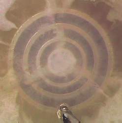
# Cell Observation: Some things to look for in a stage 3 cell:
* All cylinders should stay clean, on BOTH sides.
* The cell will remove out of the water what it does not want . This scum should be either at the top or bottom of the cell and not on the cylinders.
* You should filter this scum out of the water and keep reusing the water that the cell is converting. Only top it up, do not replace it unless you are not getting anywhere with the cell.
* You should see very small bubbles rising from both side of the cylinders.
* The top surface of the water should develop an oily type film (surface tension). This will only occur if you keep the water at the right level. The right level is meniscus height or just high enough water for the bubbles to freely flow on the total surface of the water. Obviously you should keep the cell level to achieve this.
* The cell should never get hot or even warm.
* On turning the power off, the tiny bubbles should form little islands that may be turning in a clockwise or anticlockwise direction or some one way and others the opposite way.
* The bubbles should not simply rise to the surface. You should see the tiny bubbles following eddies and meandering all over the place. For example they may be travelling in one direction between one set of neutrals and travelling the opposite direction in the next gap.
* When the cell is charged you will notice a North/South magnetisation in the vertical plane. This is normal and a good sign. On removal of the water this field should disappear.
The above is what I do and what I have observed with my stage 3 cells. You should do and see very similar results. If not, go through my points and see where the discrepancy is. That may be your problem.
Good luck and dont give up, if I can do it so can you, my only trick is persistence. Stick with one cell until you are sure that it is faulty, there is no point in changing things just for the sake of changes.
The above cell does work and has worked for many. After you are familiar with the above basic cell, then and only then move into the construction of the specialised versions.
Learn to walk before you attempt to run, saves you from falling flat on your face. … to be continued on Rexresearch.com page
(to link the article above use: #PRO)
## Buna-N (Nitrile)/Ebonite spacers, Sun Jul 16, 2006, message from the forum http://groups.yahoo.com/group/JoesCell2/
Hello all, been researching the chemical compositions of spacers.
Ebonite as compared to Buna-N …and why this has caused such a split of Peter and Alex…perhaps I am being redundant to some..but to get to the point…and it is going to be the briefest of summary as the equations to support all this activity is as complex as DNA…it is based on “cause and effect plus time…very long time”… not totally scientific here, but useable to most of all this confusion.
Alex uses acidic water and ebonite spacers to get to where he is going….and if a person takes that combination of chemicals…add the electrolysis activity (known) and what ever else is happening (unknown)…the degradation aspect of releasing certain chemical events at certain times figured at (very) long…about the rate to return to basic elements…the method is basically leaching. As the ebonite materials degrade, they support the reaction/ depletion of many of the chemical processes taking place….but at some factor (at parts per billion) per individual chemical component… the isotope effect weakens…layers are not degrading equally…
And, as, the water in the cell needs to be changed with juvenile water from time to time, to replenish/restart this process. The degradation rates have changed to the point of the ‘leaching’ of chemicals is beyond the (electrical) charge capacity …not enough power to keep in state of imbalance to break the bonds…In this situation the acetic cleansing of the tubes is beneficial.
Now to address the same scenario with using Buna-N(Nitirle) and much the same similarities to rubberized hoses…these are the products used in Bill’s Cell…but exactly which Buna-N did he use ? The Buna-N is made of butadiene and acrylonite…which depending on application the ratios are from 18% to 48% acrylonitrile…this has a tremendous implact on one very important aspect…the higher the concentration of acrylonitrile…the less butadiene…here is a great point to consider…. butadiene is released in gaseous form as Buna-N degrades/decomposes..2 ppbillion…can affect the human body..but not long term with removal of exposure( airing out the room)(getting some fresh air)and cold water rinsing…juvenile water will neutralize this bad reaction faster due to its neutral ‘absorbing’ qualities.
This gives some definition to the aspect of “bad cells” that others reported. If this butadiene is released in too great a quantity by the Buna-N.. ‘broken down too fast’ during the ‘seeding’ processes it will change the electrical capacitance of the water…basically slowing it down,,not stopping it totally…but it does become unhealthy at this point.And that may explain eyes burning, bloated face sensations,etc.
Also, the method to electro-clean the cell as Peter described in post 993…is more benefical/ condusive to the ‘isotopic quailities’ of Buna-N…depending on the ratio percenatges of composition of Buna-N.
It is not so difficult to understand why the composition of the spacers is so very important to the choosing of, and which technique to use related to the ‘cleansing process’
And, for those who think you can use both, not a wise choice…as the degradation factor(time) is different of ebonite compared to Buna-N … on the molecular levels(carbon bonds) so they will be in conflict at some point to ‘lessen’ the electrical capacitance of the cell.
Still I consider this degradation process ‘neccessary’ to the functioning of the Joe Cell…I find it amazing that Joe was able to put these chemicals together by some “internal instintive knowledge”
As I stated in the beginning, this is a brief summary, but for me, it answered “why the split of two very well-intentioned individuals” who have invested so much time and effort.
As for ‘those’ who have mentioned not using scientific methods to come to a conclusion,,,from the Joe Cellers,,,do the mathematical equations before commenting….without the correct equipment it will take about 5 years… if you are good enough…and God knows how many pages of printed materials to support the findings…just had to get that off my chest…I will be using the Buna-N myself, if someone will be specific as to the material choice (of exact percentage) made in the past, as it has a different carbon based activity in the degradation processes.
My gratitude to all people who are working on this Joe Cell project.
(to link the article above use: #JOEBUNA)
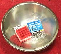
## JOE CELL KIT PARTS NOW AVAILABLE , FROM – Nutech 2000 http://www.nutech2000.com/webtext/flyers/flyerkits.html
Buy Online all the necessary parts for your JoeCell: Examples
The ‘Joe Cell Phenomenon’ is a truely remarkable technology that is right at the frontier of NEW SCIENCE..There are many dedicated experimenters that are slowy bringing this technology to a more ‘user friendly reality’. We are all on a learning curve which has only just begun, but the great thing is that the ordinary person can actually replicate this remarkable new energy source. ORGONE ENERGY ? – Call it what you want, but it is real and in reach. MANY FOLK ACROSS THE WORLD HAVE REPORTED MANY SUCCESS STORIES ranging from drastically effecting the engine to actually TOTALLY RUNNING ON THE CELL. Keep in mind that the WATER is also a key componant in the running of the cell. See the ‘water books’ in the ‘JOE CELL’ section on the ‘SHOPPINH TROLLEY’. If you think water is ‘just water’, then you better think again and get hold of these books. Water is the ‘KEY’ to to life and the Bio-energy field all around us.
# NEW FOUR INCH OUTER CANNISTER – We can supply to suit a set of 8″ inner cell tubes and 5″ inner cell tubes. The 4″ outer tube has an END CAP professionally welded and polished finish. The base is drilled ready to fit your ‘CATHODE STUD ASSEMBLY’. Heat treated.
– 10 inch ‘OUTER CANNISTER’ ( Suits 8″ inner tubes ) $ 140
– 7 inch ‘OUTER CANNISTER’ ( Suits 5″ inner tubes ) $ 130
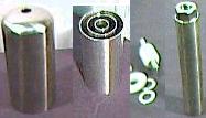
# 4″ CANNISTER INNER TUBES – 1″, 2″& 3″Diameter Tubes.
Sets come in two lengths – 5 inch and 8 inches. Each tube is machined on each end for precision. Heat treated to reduce seam magnetism to a minimum.
– 5 inch high cell set ( machined + Heat treated but not polished ) $ 70
– 8 inch high cell set ( machined + Heat treated but not polished ) $ 75
# THE CATHODE AND STUD ARRANGEMENT – In this design we machine down the BIG NUT sitting on top of the cathode tube. Allow 3 thou over size for a press fit. Heat treatment recomended. Position nut according to manuals. The stud arrangement is permanently fitted to the BASE of the CANNISTER and you simply unscrew the ‘whole Inner Tube Assembly’ for cleaning and servicing.
The nut is machined and Press Fitted into the Cathode tube.
Nutech 2000 ; P.O. Box 255 ; Ivanhoe.Vic.3079 ; Australia ; nutech@arc.net.au
# DISCLAIMER: These parts are made available for the convenience of ‘JOE CELL EXPERIMENTERS’ who are unable to obtain or construct the componants according to the manuals them selves. Please be aware that any such experiments can be dangerous and we advise you to take all possible safety precautions. The purchaser or end user of any ideas, plans or parts obtained from Nutech 2000, must ACCEPT FULL AND TOTAL RESPONSIBILITY AND LIABILITY for ANY DAMAGE to PERSON or PROPERTY that may result from any form of experiment or application of the hardware.
We will replace componants if not made to our specification or as advertised. We make no guarantee as to the performance of any hardware sold. But always ready to assist where possible.
(to link the article above use: #NUT)
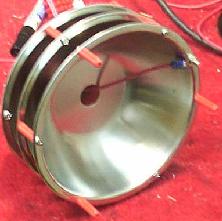
## UFD 1 – Water Charging Device (from forums)
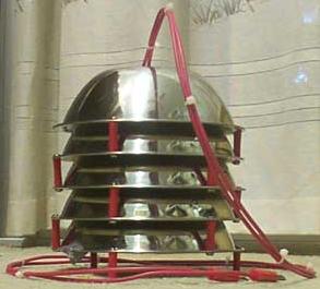
The idea was to make a device for charging water for use in jcells and to also explore the properties of electrically charged water. The device was modelled of the inverted stainless steel cone charger used by Joe and others, but designed to be easily and cheaply made at home. Five plates were used (an odd number, as recommended by Joe). The power connections are to the top and bottom plates, with the inner three plates acting as idlers.
The UFD 1 device I came up with was made from 5 stainless steel bowls. These were very cheap ones, bought from a grocery store. I did not expect the quality to be very good, but while working on them, it appeared that they were made of quite good stainless.
The Bowls were 16cm across the top. Also used were some 6G x 10mm Stainless steel PK screws, and some 25mm star plugs. The whole lot cost less than $20.
A hole was punched in the centre of the bottom of each bowl. I used an old allan-key operated punch/die set to do this. The steel proved quite tough.
I then drilled 6, equally spaced, holes around the lip of the bowl for the spacers. The bowls were then cleaned of burrs and given a wash to remove grease and such.
A connection lead was bolted to the outside lip of the bottom bowl, and the stack of bowls was built up using the 25mm spacers and the PK screws.
Three spacers were used on each layer, and also on the bottom so it would stand up from the bottom of the water vat.
The top plate connection was made to near the centre hole of the top bowl.Then both connection points were covered with RTV 732 engineering Silastic, and allowed to cure overnight.
(to link the article above use: #JOEBU2)
## Bills Joe Cell Replication
Materials Specifications
All Plate, Tubing & Pedestal parts is to be 316L Non – Magnetic Stainless Steel
These properties are specified for flat rolled product (plate, sheet and coil) in ASTM A240/A240M. Similar but not necessarily identical properties are specified for other products such as pipe and bar in their respective specifications.
Tubing – the diameters of the tubing is as follows
Negative tube is 2 outside diameter X 8 in length X 0.059 wall thickness
First Neutral tube is 3 outside diameter X 8 in length X 0.059 wall thickness
Second Neutral tube is 4 outside diameter X 8 in length X 0.059 wall thickness
Vessel or positive tube is 5 outside diameter X 10 in length X 0.059 wall thickness
Vessel Top diameter, Flange Ring & Bottom cap are 1/8 in thickness flat plate.
Welding :
The specified welding process is to TIG (Tungsten Inert gas) and is utilized for all welding attachments
Vessel
– The Flange Ring: The Flange Ring is to be placed over the outside diameter of the 5 tube and flush with the top edge there of and Fuse welded 100% if it inside diameter to the 5 diameter (Tube top) vessel.
– The Bottom Cap Plate: The bottom cap plate diameter is to be inserted into the 5 diameter tube & fuse welded 100% of its outside diameter to the 5 diameter (Tube bottom) vessel.
– Gasket material – The gasket material is to be Buna N or Butyl of 1/8 to 3/16 in sheet thickness.
John – the gasket material I incorporated was what I had on hand. Until the O-Ring top cover sealing arrangment is updated we need to spec out a common sheet type gasket material that is readily available and inexpensive or of reasonable cost.
Provide the ring gasket is cut to fit the flange rind dimensions I believe any semi pliable material is suitable because the top and the vessel carry the same potentials (+).
– Pedestal seals – the sealing washers is to UHMW (Ultra High Molecular Weight Polyethylene).The seals are to machined out of bulk material to specification as describe in drawing sheet # 4.
– Stainless Steel tube spacers– Are to Buna N or Nitrile.15 Spacers are cut from ½ diameter O-Ring stock approximately 1/16 longer than space between tubing sides. The O-Ring spacer is to be install with the cut edge contacting the tube surfaces.
– Buna N or Nitrile Material Specification: Buna N or Nitrile is a copolymer of butadiene and acrylonitrile. Acrylonitrile content is varied in commercial products from 18% to 48%. As the Nitrile content increases, resistance to petroleum base oils and hydrocarbon fuels increases, but low temperature flexibility decreases.
Due to its excellent resistance to petroleum products, and its ability to be compounded for service over a temperature range of -65 to + 275 degrees F (- 54 to +135 degrees C), Nitrile is the most widely used etastomer in the seal industry today. Most military rubber specifications for fuel and oil resistant MS and AN 0-rings require nitrile base compounds. It should be mentioned, however, that to obtain good resistance to low temperature with nitrile compounding, it is almost always necessary to sacrifice some high temperature fuel and oil resistance. Nitrile compounds are superior to most elastomers with regard to compression set or cold flow, tear and abrasion resistance. Inherently, they do possess good resistance to ozone, sunlight or weather but this can be substantially improved through compounding. However, since ozone and weather resistance are not always built in, seals from nitrile bases should not be stored near electric motors or other equipment which may generate ozone, or in direct sunlight.
(to link the article above use: #JOEBU1)
# from : http://stanleymeyer.com/phpBB2/viewtopic.php?p=206, forum.
Posted: Thu Mar 30, 2006 11:59 amPost subject: Bill Williams Car is Running on the Joe Cell !
Hi guys, I believe Bill Williams has a 1975 Ford F250 4X4 Running on the Joe Cell…..pretty amazing!
Here are the Schematics for download http://stanleymeyer.com/userupload/2/revision_5.pdf
Make sure you scroll down to see the other diagrams in the PDF. Bill is Currently working on the specs for all the materials and a semi manual relating to how I start my Cells.
Here are some Pictures of the cell.http://stanleymeyer.com/WFCprojects/Bill%20Williams/
see two video segments of the engine running herehttp://71.197.200.191/egas/files/7815463664.avi http://71.197.200.191/egas/files/7601053282.avi
see also : http://astrosa.com/n99to01/n1001.htm
## The latest about The Joe Cell, 05 november 2006 :
Inventor runs engines on ‘Proton Cell’ from http://pesn.com/2006/11/01/9500429_Proton_Cell/
“BJ” explains how his version of the Joe Cell works, and why it works, giving specific instructions about how he has been able to achieve repeated success. By Sterling D. Allan, with “BJ”; Pure Energy Systems News, Copyright © 2006
Abstracts:
BUNDABERG, QUEENSLAND, AUSTRALIA — An inventor in the Bundaberg area has been able to operate around fifteen different engines on the Joe Cell alone, with no fuel line connected. He contacted me to begin the process of providing a demonstration as well as full disclosure of how the technology works; and has worked closely with me in the composition of this piece.
Most of his engines were outside of a vehicle, though he has gotten vehicles to run on such engines as well — with no petrol fuel coming to the engine.
… Joe, who the cell is generally named after, told BJ that the University of New South Wales ran a 1976 Leyland V8 on a bench for months with no radiator.It ran cold, and they could not figure out why it was running.
… BJ discovered this phenomenon on his own in 2000, then later learned of the Joe Cell, and has spent a lot of time with Joe, comparing notes.In all, he’s spent thousands of hours in experimentation on this, along with extensive reading up on the supporting science — both established physics as well as cutting-edge.
I took 23 pages of notes in my four-hour chat with him, and will say that this information could easily fill a good book…
… Though his technology is definitely the same as the Joe Cell technology, BJ calls it a “Proton Cell”, inasmuch as he thinks that the energy is coming from hydrogen atoms from which the electron has been stripped, allowing them to slide easily through metal into the combustion chamber where they catalyze regular air coming in through the carburetor to burn in an implosive reaction.
… Weather modification, transmutation of elements, and anti-gravity are additional spin-off technologies related to the Proton Cell. He said that Joe has seen the same thing with his cell.
# Proton Cell Compared to Joe Cell
…there are some important differences….BJ appears to have identified all the crucial components, and articulates here what is required to achieve eureka.
# Finding the Right Water
The crux of what happens in a Proton Cell, according to BJ, is that “dead” water, is first rejuvenated and magnetized, at which point it can do fantastic things — like run an engine, with no consumption of fuel, including the water in the cell.Remember, too, that the cell is not hooked up to electricity when it is running an engine.There is no man-infused input.
The culinary water that comes from municipal sources is nearly always “dead” according to BJ.The impellers on the pumps and the chemicals added take away its life force.Thus BJ typically uses rainwater in his cell.He has also used water that has been purified by reverse osmosis.”Dead water will not work,” he said.
In another invention, he has devised a method for purifying and revitalizing dead water.The invention is very simple.It consists of 100 meters of pipe in line with the earth’s magnetic field. A speaker magnet is placed at the input and output ends, also aligned with the earth’s magnetic field.That alignment can be deduced by suspending the magnet by a thread and observing which way it orients, then fastening it to the outside of the pipe in that orientation.On the input end of the pipe, the magnet is situated about six inches before some ribs that are cut into the pipe to cause the water to spin as it passes by them.On the output end is the same configuration, but with the spin prior to the magnets.Mirky water goes in one end, and purified water comes out the other.And the crud is not collected in the pipe.That technology obviously is deserving of further attention and development.
Microwave transmissions are another thing that meddles with water’s natural form.High-rise buildings often have microwave transmitters at the top, so collecting rainwater in that environment would not be advisable.
“Pure water is the best dielectric,” BJ says.He illustrates this to people by taking an electric drill and submerging it in a barrel of pure water, while the drill is on, then running the drill completely under water!(Don’t try this at home unless the water reads zero TDS (total dissolved solids).)
# Magnetizing the Water
What the Proton Cell does is take this pure water and align it magnetically.The voltage introduced between the cathode (innermost ring) and anode (outermost ring) creates a scalar magnetic potential that entrains the water. “In the process of this alignment all previously stored memories of frequencies are erased and the water is restructured.”
This magnetized, pure water, is then able to entrain the surrounding media (the water jacket and metals of the host engine) to reproduce the same frequencies on an atomic level.
The protons that emerge from the cell, channeled by the hose to the engine, then pass easily through the engine block, where they catalyze the indrawn atmospheric air to combust implosively.
# The Stainless Steel Has to be Non-Magnetic
Having the right water, is one key to a properly-functioning Proton Cell.Another key is that the stainless steel used in the cell needs to be free of any magnetic attraction.
One way BJ recommends to detect if there is magnetism in the stainless steel is to suspend a neodymium magnet by a thread, and then dangle it near the steel. It shouldn’t deflect at all, anywhere near the entire surface. This is far more sensitive than merely holding a neodymium magnet by hand. The level of magnetism that can cause the proton cell to not work is much less than can be felt by holding the magnet by hand.
Most so-called “non-magnetic” stainless steel is slightly magnetic or can become so by cold working, polishing, and welding. BJ recommends that the tubes of the telescopic cell be extruded, not welded from sheets. Specifically, he recommends ISTM A269 Grade 316, “which is still slightly magnetic but will work successfully.There are other grades as well but I have not tested them yet.It appears that A269Grade 316L seamless tube is extremely non magnetic; but each piece needs to be tested with the neodymium magnet on a string method.”
“No attraction is desirable but extremely faint attraction will still work.”
The one exception to this is that the outer-most cylinder of the cell can be Tig welded to the base plate.For some reason, a little magnetism in that position does not seem to be detrimental to the cell function. “Make sure the Tig welding rod used is the same grade as the stainless used.”
The lid, however, is crucial, and should not have any magnetism in it.
# Non-Magnetic Lid Fabrication
It is not feasible to shape the lid the way it should be without introducing magnetism into the stainless steel. So after the lid formation is completed, it should be annealed in a high-temperature kiln (around 1100° F), and then quenched.That will remove the magnetism.
Most industrial machine shops are adequately familiar both with how to shape the lid per spec as well as how to anneal and quench it when it is done.
When the lid has been shaped, you will see a rainbow of coloring in the metal.This goes away after the anneal/quench process.
“Warning! Machine polishing can make the stainless magnetic. All polishing should be done by hand using wet and dry paper.”
I would think that one would want to similarly treat the outmost cylinder that has been Tig-welded at the bottom, to remove the magnetism in the weld.BJ agrees that this would be beneficial, though not essential.
While the exact shape of the lid is not that crucial, it is important that it not have any sharp corners.
BJ recommend that the lid have a friction fit around the outside of the outer cylinder.It should then taper toward a 45-degree or a 90-degree angle.Then it should taper into the nipple where the hose fits onto it.The 45-degree angled lid is probably best — like an up-side-down funnel.Bill William’s lid was 90-degrees, and it worked.
Once the lid is friction fit onto the cell, some kind of tape can be used to prevent leakage of fluid from the cell.There needs to be a continuous electrical connection around the perimeter of the cell with the lid on the cell, so a gasket fitting would not be appropriate.
“On a dark night, when the cell is charging, you can see dancing light effects through the nipple near the top of the taper. I believe the word for this phenomena is called triboluminescence. The fact that this happened in the narrowest part of the taper points to some kind of concentrating effect akin to causing more electricity to pass through smaller wire. Blue light is associated with orgone energy, and proton energy, as well as high voltage discharges.”
# Cell Shape Not Crucial
BJ says that the cell configuration is not crucial. He has used flat plates as well as telescopic. The important principle is to use non-magnetic materials, and to set up a voltage gradient. The neutral plates should be spaced evenly between the anode and cathode plates, and can be as far apart as one inch, or as close as 1/8th of an inch. BJ usually stays within 1/4 to 1/2 inch spacing between plates.
This is not an electrolysis paradigm. The objective is not to electrolyze the water into hydrogen and oxygen. In fact, this should be avoided. When a cell is electrolyzing, it is not charging the water. The objective is to generate charged water in the cell, which is then applied to the engine — not to produce hydrogen/oxygen gas. The Proton/Joe Cell set-up is not designed to produce hydrogen/oxygen (Brown’s) gas to be fed into the air intake. This is not a hydrogen boost ( http://peswiki.com/index.php/Directory:Fuel_Efficiency_Hydrogen_Injection ) scenario.
# Types of Insulators
BJ has found only four types of insulator that work well in these cells: clear polycarbonate tube, balsa wood, pine doweling, and clear glass. But there are many others that have apparently worked well for some people. Polycarbonate tubing is difficult to work with, but can be cut into segments for spacing.
If your chosen insulators are leaking energy, the cell will slowly die. This is evident because the voltage potential measured via multimeter between the cathode and anode will slowly drop to well below half a volt. “My cells can sit on the bench for months without recharging yet never drop below one volt.”
“If the insulators are failing they will allow electricity / energy to travel around the outer surface of these insulators, resulting in serious damage to the stainless, all around where the insulators contact the alloy, leaving deep etch marks up to three paper thicknesses deep during charging. This kind of structural damage will lessen the chances of success. Such a cell will not hold energy potential, and you are wasting your time trying to run a car from this cell.”
# Cleanliness & Transmutation
BJ and Joe have observed that a small sample of certain substance placed in the cell will be duplicated over a period of hours when electricity is applied to the cell. BJ has seen this with a couple of dozen compounds including sulfuric acid, alcohol, CFCs, and Mango fruit. Given enough time (e.g. around 24 hours), and the proper current and voltage, a substantial portion of the water appears to transforms into the introduced element, carrying all its properties. “Some kind of hydrogen replication effect on an atomic level,” BJ conjectures.
One time, BJ observed one of his engines run on a small volume of gasoline that was being created on the spot. This was witnessed by a mechanical engineer, who, for the hour that the engine ran, checked numerous times for possible sources of fuel. The engine would have run for maybe two to five minutes on the amount of fuel that was present. The CO/CO2 and other emissions were definitely the product of petrol combustion.
“The engine will not run on proton energy until every last drip of petrol has been consumed, or else it will continue to run as though petrol were being supplied to the engine even with fuel lines disconnected.” Some petrol can be trapped in the corner of the fuel filter and remain for extended periods until it finally evaporates.
Considering this apparent transmutation phenomenon, it is important when assembling the cell that you try to be as clean as possible. BJ cleans his stainless steel with methylated spirits, and wears cotton gloves while assembling the cell.
He thinks that not doing this is most likely why many Joe Cell researchers find scum build-up in their cells. It is a replication of any crud that was introduced during assembly, or that was contained in the water. One must especially stay away from grease and oil, including the natural oil/grease from fingers.
Obviously, this effect alone, if real, opens an entire field of study with far-reaching ramifications. While one might not be able to replicate anything larger than a molecule, it could come in very handy for inexpensively producing perfumes, drinks, fuels, and other liquid commodities.
The electrolytic capacity of the water will change as the water is transmuted, becoming more conductive, requiring a modification of the input voltage and current to maintain an optimal level and avoid heating.
# Cell Charging Method
Once the cell is assembled, you are now ready to add the water and charge it. BJ advises that the cell be charged before hooking it up to an engine. BJ prefers to fill his cell all the way to the top of the outer cylinder, which is a few inches higher than the cathode and neutral cylinders inside. He recommends that the water be at least an inch above the cathode and neutral cylinders.
A 12 volt car battery is used to power the cell. (BJ has successfully used as small as 3 V and as much as 30 V) If using AC rectified, use a full-wave rectifier. An electrolytic capacitor can be added to the full wave rectifier to smooth out the quality of the DC voltage delivery.
Position the cell away from power cables, lights and all other sources of electromagnetic/alternating-current pollution. For best results, charge the cell on a wooden bench at least three feet from the ground for about ten to twenty minutes, depending on the water quality.
As the cell charges, the water expands, pushing some water out the top of the cell. BJ doesn’t put anything under the cell to catch this spillage onto his wooden bench, saying that “it adds beneficial energy to the work area. This is useful when working with this energy. Joe told me that the energy in his shed was so powerful that even people who could not get their cells working at home were able to succeed in his shed.”
When the cell is fully charged, large bubbles will cover the surface of the cell. (Most of the bubbles spill out when the water overflows). If the bubbles collapse quickly when the leads are disconnected, you have an insulation leak either in the main insulators or below the anode, between the body and anode case. When the cell is working properly, some bubbles will remain on the water surface for days, and will implode violently if ignited. This indicates that you have a fully aligned cell, with no additional charge required.
When charging the cell for use with an engine, not transmutation, there is no need to regulate the voltage. “If you make a cell specifically to experiment with transmutation of elements (creating compounds), long charge periods are required (up to 12 hours). It all depends on what your cell is duplicating. If sulfuric or other acids are cloned, the water conductivity will increase dramatically, leading to increased electrical resistance; and the cell will run extremely hot. This requires patience and careful observation, but it is greatly rewarding to see things take place that are only mentioned in cold fusion reactions (transmutation of elements).”
After you have charged the water in the cell, pour the charged water into a glass container. Rinse the cell with distilled water. When all impurities have settled from the charged water in the secondary container, slowly tip the charged water back into the cell, leaving the impurities behind. If the cell is working properly, the residue will settle in a few hours. If the cell is working less than optimally, you may need to allow the residue to settle overnight.
If the cell is properly insulated, the magnetic charge should persist indefinitely, especially if two neutrals are placed between the cathode and anode. Compromises in the insulation will result in a gradual discharge of the electromagnetic properties of the water.
# Amazing Water Properties
The water that has been charged in a cell has numerous astonishing properties. For example, BJ describes pouring some of the water into a polluted creek, and the water around it cleared for nearly six feet in diameter around where the water was poured.
He says that Joe has given it to people who have drunk the water and had various ailments clear up, such as cancer. Apparently the charged water reprograms the water within the human body (like the polluted creek), causing the body to release toxins in similar manner.
It is the water that enables an engine to run, not the cell. “The cell creates the environment that organizes the water into a charge separation and re-polarization of its crystal structure. The water then channels protons from the host cell through the delivery tube to the engine, extending its energetic nature to reprogram the metal and water (in the cooling system) into its charged atomic, energetic state.”
One time, BJ added charged water directly to a car’s coolant system. Two things happened. The coolant dropped out of solution, and the engine ran on the proton energy, though no cell was attached to the car. If the car runs cool enough on proton energy (and engines thus running generally do run relatively cool), this method could be much easier than installing the cell in the engine compartment. Just how long it would last has yet to be documented.
This being the case, one would think that any engine that has a charged cell applied to it will see the anti-freeze drop out of suspension, similar to what was observed when water was added directly to the coolant. BJ thinks this will be true. “Charged water will not hold dissolved solids in suspension as will dead water, which holds everything in suspension.” Joe has observed the same thing.
BJ said, “I sat charged water next to a bucket of dirty water, which began to slowly rotate counter-clockwise. Then all suspended dirt fell to the bottom as I watched.”
# Works on Air-Cooled Engines Too
While an engine’s coolant system provides a simple way to entrain an engine, the proton cell effect also works on air-cooled engines, which opens this application to motorcycles, for example.
BJ got the cell to work on a bench-mounted Kohler engine, designed as a multi-purpose, stationary work engine. The V Twin fuel-injected engine with electronic ignition and fuel injection, is air cooled.
# Weather Modification
“When you run one of these Proton Cells outside, with the lid off, you can see a small clearing in the sky directly overhead, where the protons are rapidly ascending”, said BJ. “I’ve routinely seen rain spawned on what began as cloudless days. It is not unusual to see rainstorms in the vicinity of my home, and nowhere else. Very often you get an inrush of air when the cell is turned on. These effects don’t happen as much when you’re inside, because there is enough mass to absorb or deflect the rising protons.”
… Cloud busters were originally designed by Wilhelm Reich. (Ref http://www.orgonelab.org/OROPAZ1989.htm ) This rain-making technology was successfully used to create rain in Arizona, USA in the 1980s. There are many similarities between this orgone energy advanced by Reich, and Proton Cells.
One thing to bear in mind when using these cells is that such interactions with the atmosphere are easily detectable by weather satellites. If security is a concern, blowing holes in the clouds (immediate vicinity, while propagating rain generally), might not be a good idea for keeping yourself anonymous from the powers that be.
# Installing the Cell to an Engine
After the cell is charged, you should not touch it with your bare hands because that will slowly discharge it. Use some kind of low-level insulator such as dry paper or gloves to hold the cell and transport it to the engine for installation.
The cell needs to be insulated from the car and/or engine, except for the cathode post that protrudes from the bottom of the cell, which should be connected electrically to the body of the car or engine. The insulating material can be of a regular sort, not special like is required inside the cell.
The cell needs to be situated as far away as possible from higher voltage lines in the engine compartment. If there is no suitable location in the engine compartment, you might try installing it in the passenger bay, running the hose through the fire wall. The trunk could also be used, so long as an up-hill rise can be maintained in the hose leading from the cell to the engine.
Once the cell is charged, it doesn’t need to be connected electrically to the car battery. But the cathode does need to be connected electrically to the car (ground). The anode portion of the cell, continuing through the hose leading from the cell, needs to be insulated from the car.
# Connecting the Hose from the Cell to the Engine
The hose running from the lid of the cell to the engine can be composed of just about any non-magnetic material. BJ typically uses a plastic hose or a stainless steel tube. An aluminum tube will work too.
You should avoid any sharp turns in the hose, inasmuch as most protons will pass right through the sharp turns, rather than be guided to where you want them to go.
“The cell delivery tube must be slightly lower than the destination point on the engine because proton energy will not travel in a downward direction.” This could pose engineering challenges for vehicles such as jeeps that will encounter significant inclines. BJ responds: “The cell can be mounted in a low position even below the engine mounting level on the body. Then the delivery tube can rise to a high position on the motor. Rising sharply is no problem.” (See note below about removing a cell from an engine that has been entrained, to see that achieving a functional up-hill hose orientation is not a crucial issue.)
The entire length of the hose should be insulated electrically from the car. It should be treated electrically as an extension of the anode of the cell, even if it is electrically non-conductive. The path of the hose should avoid any higher voltage sources, such as the spark plug leads, the distributor, and the coil.
The end of the hose should be situated no more than four inches from the engine block, but should not electrically touch the engine block, and should ideally be oriented so that the emerging protons can penetrate into the cylinders through the metal.
# Converting the Engine to Run on the Proton Cell
Remember, now that your cell is charged, you do not need to connect the cell to the battery in the car, nor should you. Once the charged cell has been installed, with the hose leading to the engine block, properly insulated, the next step is to convert the engine to run on carburetor air via the proton energy catalyst.
This is not as simple as just disconnecting the fuel line and then running the engine on the proton cell. There is a transition that takes place.
BJ describes the fuel actually beginning to flow backward, away from the engine, as the proton energy begins to take over.
Do not begin to adjust the timing until after the proton energy effect has fully kicked in. The engine will run without the timing being adjusted, but does not achieve its full potential until the timing has been advanced.
You can tell that the effect has fully kicked in when you can disconnect the fuel line and the engine continues to run. Remember to check the emissions, though, because it could be running from the petrol-duplication effect. Be sure all of the petrol has passed out of the system.
Once the engine is running on air, via the proton input, the timing will need to be advanced until the engine runs smoothly. “The engine will tell you when you have found the right position, because it will run ragged either side of the correct position, but will run smoothly when the correct timing position has been reached. The engine will not run from petrol in this new timing position.”
You may want to let the engine run like this, without going anywhere, for two or three days, to entrain the system, so that the system will be more impervious to external “frequencies” you might be subjected to while driving down the street.
Once this has been done, it should drive just fine, but with significantly more power and pick-up. The increase is around two-fold.
Not only does the engine have more power, but it can rev up to much higher rpms without stressing the engine.
The accelerator still functions to govern the speed of the engine. The ignition key still functions to start and stop the car, inasmuch as the starter motor is still required to get the engine turning; and shutting off power to the spark plugs will shut the engine off.
BJ says Joe’s engine ran without a distributor cap or plug leads, so be prepared for possible exceptions to this rule of ignition key being able to turn the car off; and make sure your brakes are in good condition.
BJ has been able to get fuel injected petrol engines and carburetor engines to work on the Proton Cell, but has not yet tried turbo powered petrol or diesel engines. Diesel injector pumps are designed to use diesel as a lubricant, so it stands to reason that some modification would be needed.
BJ has not yet done longevity studies, but intends to include this in the planned demonstration.
# Cool Emissions
When the engine is running on nothing but air and the proton catalyst, the exhaust is clean. BJ says he has breathed it in, and it smells like clean air. The temperature is not hot either, just warm. He has not done extensive studies on the emissions. The emissions testing equipment can be cheaply purchased, if one wishes to investigate this area.
# Implosive Reaction
The experimentation done on Proton Cells points to the reaction they induce being an implosive reaction, not explosive.
That is why the timing needs to be advanced so much on engines that run with the Proton cells. “I believe this is due to a plasma field effect,” said BJ. “However this remains open to more investigation. I can only speculate on the exact processes taking place.”
Why the engines run so much more quietly is another matter for more research.
When BJ’s wife was using their Chrysler Sigma that had been converted over (without her knowing it), she couldn’t hear the engine, and thought the car had stalled. When she turned the ignition on again, and heard the grinding of the starter motor, she realized that it was running. Then, she put her foot on the accelerator, and the car bolted with tremendous power. Nine months pregnant, and in the middle of a move, she was not very happy with her husband about having to drive home by herself for an hour that way. (The effect had kicked in fully after sitting over a storm culvert during a storm, at the place she was visiting.)
On non-distributor engines (most modern cars), the only way to adjust the timing is to do so artificially by physically slotting the crank angle sensor backing plate to allow adjustment (will most likely void the warranty — as will the addition of the Proton Cell).
Carbureted and fuel-injected engines are really the only practical retrofit application of the technology without a from-the-ground-up design.
# Anti-Gravity Effects
Some experimenters with the Joe Cell technology have reported the levitation of their vehicle in conjunction with the cell. Joe tells of a time when he witnessed all four wheels of a truck being lifted 1/4-inch off the ground. He was actually was able to pass his hands under the wheels.
BJ believes this has to do with a Schauberger effect that appears “when something reaches proton saturation.”
Another effect that has been noted with Proton/Joe Cell usage has been reduced inertia when going around corners.
# Scalar Waves and Metal Memory
For many years it has been scientifically recognized that water has a form of memory. Water crystals have been observed to change shape and structure as influenced by the emotions of humans. All living things produce scalar waves. Our brain and body produce scalar electricity. “It is part of what allows us to think and move.”
“The water within us is affected by frequencies. The same holds true of the water in Proton Cells.” It is scientific fact that various metals and alloys have a form of memory also. Take memory metal, for example, now widely used by surgeons due to its ability to be bent completely out of shape and remember its former shape at a given temperature.
Proton Cells — both the water within them as well as the metals — are affected by all frequencies in their environment. However, external influences diminish as a cell becomes trained in a function, becoming more impervious to externally imposed frequencies. When a cell is first being activated is when it is most susceptible to external frequencies. The same holds true of when a cell is first applied to an engine. After it has been trained, it becomes nearly impervious to external frequencies.
# Disconnect Cell from Entrained Engine
BJ says that after the engine has become entrained, the cell can probably be removed. It is no longer needed.
The Chrysler Sigma that his wife had the hair-raising experience driving, had to be sold around the same time, as part of the move. BJ said that “the effects were still present after removing the cell, just before selling the car. Perhaps the new owner got some unexpected bonuses.” Conceptually one cell that is electromagnetically charged could be placed in an assembly line, entraining one car after another (given enough time on each), without having to be recharged, until the cell malfunctioned (e.g. shorted out). BJ responds: “Yes, the whole area will speed the reaction with constant use. Everything in the factory will be altered to the same energy as the cell.”
“Until some yahoo walks in with a bad attitude?” I Skyped to BJ. “When a car is running well on the Proton Cell, you won’t see those effects“, he said.
# How to Reprogram a Cell
A malfunctioning proton cell can be cleared when it is behaving contrary to how it should operate electromagnetically. “When a cell is assembled, we order the direction of the electrons flowing through the water between the cathode and anode by which way we decide to place the power supply leads. If negative (cathode) is placed in the middle of the cell with the positive (anode) on the outside then the most visible reaction will flow from negative to positive through the plates or tubes. An equally strong reaction will flow from the positive back through the water to reach the negative attempting to reestablish equilibrium because energy will naturally return back to its balanced state. But we don’t want that to happen just yet.
“If any one of the cell plates or tubes has been imprinted with a magnetic polarity contrary to your chosen electrical polarity, then this cell plate or tube will oppose the energy flow of the entire cell system causing some of the electricity to flow in a counter rotation and completely backwards to all other cell plates. There is no way that this unit will ever run a car, because the water molecules can not be polarized in a cell that is fighting the flow of energy. With careful observation you can visibly see the reactions within the water actually running in the opposite direction to the other ALIGNED plates. “There are only two solutions to remedy this problem. (A) Remove that reverse polarized plate or tube, throw it in the recycling bin and replace it with another piece. Nine times out of ten this will correct the problem. (B) Try annealing the piece to wipe the reverse field then start again.”
# How to Erase Frequencies from Stainless
Stainless steel has a molecular memory of sorts. If, for example, you expose the alloy to high frequency laser or plasma cutting technology, you have imprinted those frequencies into that alloy while cutting it, as assuredly as recording audio input on a recording tape or CD.
All unwanted frequencies can be erased using the following procedure.Completely drain the cell of water, turning it upside down to dry. Use an electrical extension lead. Remove the female plug, and fit alligator clamps to the positive and negative wires, making sure you leave sufficient length of bared wire for clamps to be separated adequately.
Find a place where nobody can come anywhere near the cell (to avoid electrocution). Sit the cell in a dry plastic bucket. Join either clamp to the positive of the cell then join the other to the cell negative. It doesn’t matter which, because AC alternates in both directions, changing polarity many times every second.
Making sure that no human can come anywhere near the cell, plug the extension lead into the power point then turn the power ON. Let the 240 volts AC flow through the cell for about two hours, then turn the power switch off. Pull the plug out of the power point and disconnect the clamps. The cell’s stainless plates or tubes have now been totally depolarized and scrubbed of all undesirable frequencies. This procedure is akin to a head demagnetizer.
Now the cell is ready to be filled and for you to hook up your DC power supply to attempt to align both the stainless steel and the water molecules. If everything is now free of reverse polarities, and the cell is adequately non-magnetic, the cell should now align itself. The water molecules within this water capacitor arrangement should now align to polarize, and the water should become magnetic.
# Here’s to Success
No technology is fool proof, but this technology is not complicated once understood. There must be a successful formula for every technology to operate. Hopefully, that is what has been provided here. “We just need to understand the way this technology wants to work. Then the results can be duplicated with a far higher success rate.”
# Pending Demo
BJ said that he would like to do a full video demonstration with a New Energy Congress witness present as soon as possible, but that it might take a month or so. He is dusting things off, and needs to get a suitable car to install it in. He estimates that he needs around $4000 US to pull this off. If you want to contribute toward the support of this project, BJ has authorized us here at PES Network to accept funds on his behalf.
(to link the article above use: #LAT)
## from a JOECELL forum, At 02:59 PM 4/24/2006, you wrote:
Hello list,
I’ve been watching the posts on this list for the past three weeks, roughly. Lots of posts, no real proof has been brought forward that would withstand intense engineering or public scrutiny. My company and I have been involved in research regarding Nikola Tesla and Viktor Schauberger and reverse-engineering most of their lesser-known inventions, most notably, the Tesla Turbine and Pump, and Schauberger’s Repulsine. With that said –
Here’s my offer to the group – if someone sends me plans/blueprints of a Joe Cell design that they KNOW operates as claimed, along with any additional instructions necessary for proper operation – my company, Global Energy Technologies, Inc. (formerly International Turbine And Power), will build the Joe Cell to those specs, do all the necessary engineering validation tests, publish the results publicly, with complete, detailed engineering reports, data, and digital media such as pictures and video of the unit running, and operating a standard internal combustion engine – and – we will then commence to produce the devise in quantity “at cost” to anyone who wants one. This list members will get first pick on the “at cost” units.
We will also establish two outside engineering sources for a double-blind second and third party verification for further proof of the Joe Cells operational worth.
Now…is there someone on this list that has:
1.) Actually built an operational Joe Cell and had results good enough to state that it will operate a standard, internal combustion engine as claimed? and
2.) Is willing to send us all the necessary information to duplicate that work?
Note – we are Professional Engineers. It will be built to commercial grade standards, per the instructions and details you provide. I’ve gathered quite allot of info on my own, but, nothing that shows any type of proof this devise will operate as claimed, as yet.
Now…if someone will stand up to their beliefs and send us the necessary, complete, all-inclusive information, we will gladly begin the work of replicating, building, and testing the Joe Cell for a potential (depending on the results, of coarse) commercial release. Any takers??? I am willing to build it to your specs, test it, and then sell these Joe Cells at our cost to anyone who wants one – if someone out there has actually BUILT one and VERIFIES that the Joe Cell works as claimed. I’d really hate to see that with all this information and all the claims floating around on this list (and other sites) that this turns into another smoke and mirrors show.
Send us some quality information, and we will begin work, immediately.
Sincerely, Frank Germano, President, Global Energy Technologies, Inc. www.frank.germano.com , frank@…
(to link the article above use: #JOEGERM)
## Joe Cell: Instructions: Polarity of Pipes, from PESWiki http://peswiki.com/index.php/OS:Joe_Cell:Instructions:Polarity_of_Pipes
The importance of having proper alignment of pipe polarity in the Joe Cell Replication Project http://peswiki.com/index.php/OS:Bill_Williams’_Joe_Cell .
# Pipe Polarity : The following was composed by John Carter of Australia on April 19, 2006.
Most people do not believe that pipes of non-magnetic material such as copper or stainless steel could have polarity, but they do.
In assembling the Joe cell, it is preferable to align the ends of the pipes with their polarities. That is, with positives at one end, negatives the other.
To determine this, a simple device called an L-rod can be used or a crystal on a string. L-rods are often used by water diviners to locate underground streams prior to sinking bores. L-rods give a much quicker answer than a pendulum. With practice only one rod is required
# Making an L-Rod : A set of L-rods can be made from pieces of brazing wire (~1/2 meter long, brass welding rod). The insulation on the handles can be obtained from the hard plastic 1/8-inch riser tubes used in garden irrigation systems.
L-rods are very sensitive and can pick up the magnetic radiation from your TV and computer screen, microwave oven and electrical meter box. I have had the local power company take readings at each of the above mentioned electrical devices with a Gauss meter but this meter fails to record a reading more than 1.5 meters away from say the meter box, yet L-rods indicate there is a field from over 6 metres away. Of course the L-rod does not give a readout as does the Gauss meter but it is a handy indicator.
Placing a small Orgone generator on the computer or TV screen or meter box will scatter the harmful magnetic radiation and turn it from negative to positive energy.
# How To Find the Polarity of a Tube :
If using two rods, grip a wooden dowel in a bench vise and slip the pipe over it, making sure that the end of the pipe is not too close to the metal vise jaws else the rods pick up magnetism from the steel.
Gripping the insulated handles of the rods, point the ends towards the end of the pipe. The ends of the rods will swing out for positive and swing in for negative. Mark the result on the pipe end.
When you do this, check your reading about 3 times to ensure that the reading isn’t becuase the rods aren’t being held straight.
Incidentally, if one of the tubes is placed in the cell with the opposite polarity of the others, it will manifest increased heat in relation to the others. This difference can be felt by touch.
# Preferred Alignment of Tubes : All of the tubes should be of the same orientation in respect to their polarity.
{??}And the tubes should be placed in the cell with the positive end up, and the negative end down.
# Validation : On April 22, 2006, Bernie Heere reports that he followed these instructions and that he liked the results. [1] (http://groups.yahoo.com/group/JoesCell2/message/561) “I made some L-rods, and tore down a cell that was fighting me and tested the tubes. What a kick. Works just like it’s supposed to, and I re-assembled the cell with proper polarity.” [2] (http://groups.yahoo.com/group/JoesCell2/message/538) [3] (http://groups.yahoo.com/group/JoesCell2/message/561) followed PESWiki instructions (http://groups.yahoo.com/group/JoesCell2/message/593)
(to link the article above use: #RODS)
## How to Make and Run a Joe Cell, from Pesn http://pesn.com/2006/04/27/9600265_Make_Run_Joe_Cell/
Interview of Peter Stevens by Adrian Mutimer, to further pin down the process of how to build, prime/charge, and then run a car on a Joe cell. by Adrian Mutimer
# Introduction : What follows is a presentation of material taken from a video-interview conducted with Peter Stevens on 23 April 2006, and reordered into categories that are important to the cell builder. It is not a full explanation of how to make and run a Joe Cell. It relies on the reader having a background in cell work. The quickest way to get that background is to read The Experimenter Guide to the Joe Cell (hereafter the Guide). This document emphasizes, adds to, and in some cases modifies, what you read in the Guide. Readers will also need a copy of the cell drawings, as found on the Yahoo group Joecell2, alongside them when reading the section entitled Cell Design,
# Electricity : In order to talk about the use of electricity in cell work (cellery) you have to get used to an alternative way of thinking about how electricity works.
In school we were told that the negative terminal and the positive terminal of a battery delivered no electricity at all to an open circuit and that a load was required across the battery positive and negative terminal for electricity to flow. Well according to the view of electricity you are going to get here that view of electricity is incomplete. The negative terminal of a battery is active when connected to a load without any connection, or involvement at all, with the positive terminal. This may also be true of the positive terminal, but the positive terminal is not used alone in cellery. In what follows, the action of a negative terminal of a DC power source with no positive attached will be referred to as negative electricity, When talking of negative electricity the term load is also rather misleading so it will not be used again.
# Applying Electricity : In applying electricity to cell work, one general rule that comes up repeatedly is as follows. When you want to charge water in a cell or charging vat, you first apply negative electricity, then you attach your positive lead (and normal electrical current will flow); then you take off the positive lead and return to negative electricity; then you (sometimes) take off the negative lead. We will call this the negative first and last, rule. Please take careful note that you should not rush steps one or four when you apply this procedure. When you put on that negative lead allow significant time to elapse before you put on your positive lead. It is doing something!
Closely related to this procedure are two principles of the application of electricity in cellery. The first is that the energy we are dealing with is negative in charge and is therefore attracted to positive. It follows from this that you put your negative potentials where you want your energy to flow from, and you put your positive potentials where you want it to flow to.
BUT that is just to get things started. You take the positive off pretty quickly because the second principle is that the energy does not like positive electricity at all, so you want to minimize the involvement of positive in the entire process of cellery. Timings are given below.
# Power Supplies : For your electricity supply use a 12v car battery, a 12 volt battery charger that delivers preferably linear (not pulsed) DC, or a variable DC power supply set to about 12 volts of preferably linear (not pulsed) DC.
# Magnetism : It isnt that important that your cylinders be of very low magnetism. Magnetism does have a negative effect on the good working of the cell, so it is preferable to have good quality (low carbon) steel if that can be arranged easily. If that is not available, the effects of magnetism can be overcome as follows.
– 1. Line up all your seams (assuming you are not using drawn tubes). The seams are often the most magnetic part of the tube so by lining them up you only have one segment of the cell that may be of reduced effectiveness. If, after doing that, you have tubes or seams that you suspect are interfering with cell performance because of magnetism there are three more ways to go.
– 2. Striking and sparking the cylinders. Get a 12v battery and align it with its negative pole East and its positive terminal West. Put your negative lead on the outside of the base of the tube. Then strike the cylinder along its seam with a hammer (along its length if there is no seam). Then spark the inside of the tube at the top with your positive. Then take off your negative. The striking of the hammer disrupts the alignment of the ions Note: it is essential to spark your tubes if you have polished them .
– 3. Cylinder rotation. Take the cylinder that you think may be at fault and rotate it 90 degrees clockwise.
– 4. Cylinder inversion. Cylinders have lengthwise alignment of magnetic-type swirl of frequency. You want all your North poles (positives) at the top and all your South poles (negatives) at the bottom. The way you test the cylinders in this regard is with an L-rod which is a type of divining instrument. John Carter is the expert on this and he has put up comprehensive instructions elsewhere. Also, check out Walter Russell on this, he explained what he termed twin field poles.
An alternative way of assessing which cylinder(s) should be inverted is to get all your cylinders standing up on your bench and crowd them together (not nested). Leave them for minute and then place your hand on top of the entire set. You will feel heat in any cylinder that is in opposite alignment to the rest.
# Cylinder Cleaning : Only ever electro-clean the cell cylinders. Therefore, do not chemically clean them! To do this you reverse the current along the length of each tube with the cell fully assembled.
Start with the outermost cylinder.
(i) Put your positive on the inside skin at the top of the cylinder and your negative on the outside skin at the bottom. Leave this in place for one minute.
(ii) Put the negative on the inside skin at the top and your positive on the outside skin at the bottom. Leave this in place for one minute
(iii) Repeat (i) above.
When you have done this to the outermost cylinder go on to next cylinder until all the cylinders have had the treatment.
# Water Cleaning and Charging : You can use water out of the tap as long as you largely clear it of the chemicals put in there by the water company (alum, chlorine, fluorides etc.). To do this you can use a cell.
Put your tap water in the cell then do the procedure described above under Applying Electricity. No electrolyte should be added.
Attach the negative of your 12-volt battery, battery charger or 12 volt DC supply at the base of the cell and leave it on for between 2 and 20 minutes. Then, leaving the negative in place, put the positive at the top of the cells outer cylinder for between 2 and 3 minutes. Then take off the positive, and leave the negative on for up to an hour.
Pour the water into a glass container or plastic bucket. Repeat.
After 24 hours, the chemicals in the water in the bucket will have become solids; some will have dropped to the bottom and some will have risen to the top, depending on what charge they acquired in the process. Pour off the solids at the top, then pour the middle (clean) water into your cell, then throw away the stuff in the bottom.
Although you can use pulsed dc for this, flat dc works faster.
If you do the same process as above with a charging vat, you will wind up with a good deal more water and no need to fiddle about with repeating your charge procedure. In passing, and while we are talking about charging vats, those cones that you see in The Experimenters Guide to the Joe Cell come from the kind of milk/cream separators used in dairies.
# Cylinder Spacers : These should be of natural rubber without additives. Some Buna-N O-ring material works but some O-ring material is mineral based, or contains iron in the colouring which will short out the cell.
If the spacers are of tubular rubber they should be set with the tunnels of the tubes all pointing inwards towards the centre of the cell when viewed from above. (see image below). It is important to get this detail right to prevent shorting.
The insulating capacity of the spacers is further enhanced by adding a dab of white Sikaflex 291, Marine Grade, to the ends of each spacer.
# Spacer at the base of the cylinder set. This should be of alabaster or the same plastic used in kitchen cutting boards
# Cell Design : The following is expressed as a set of deviations from the design found in The Experimenters’ Guide to the Joe Cell http://members.iinet.net.au/~langfamily/Experimenters%20guide%20to%20the%20Joe%20Cell.pdf .
Bills drawings, as found on joecell2, are right. Have them by you as you read this. Note that any deviations in this text override the drawings. As your central cathode, a 1-inch tube is too narrow, allowing the energy insufficient space to resonate. Use a 2-inch tube as your cathode.
Apply your negative charge to the outside skin of the 2 inch tube by means of a plinth or cathode hub-platform that sits at the base of the 2 inch cylinder (see images below).
Readers will recognize that this instruction is contradictory to the Guide which has the negative charge delivered to the inside skin of the central tube by means of a press fitted bolt. It also contradicts Joes statements in the transcripts available in joecellfreeenergydevice http://groups.yahoo.com/group/joecellfreeenergydevice Yahoo!Group.
The argument behind this way of proceeding is that the energy seeks positive charge, and you want that energy in the middle of the cell. By putting the negative on the outside skin of the central tube you cause an attractive positive charge on the inside skin, and the energy migrates to it.
In order to have water flow in your 2 inch cathode cylinder you must drill three holes in the plinth or cathode hub-platform.You can use a flange top or cone top as you wish. because cone tops are harder to get and cost more, a flange is indicated.
# Cell Placement : This can be anywhere convenient but it must be at least four inches clear of the high-tension leads and electrical gear (distributor, etc.), and also four inches from the radiator, air-conditioning hoses and fuel lines.
# Cell Fastening : Use an embracing clip or bracket; note that it must be VERY well insulated. The cell shorts out to the car very easily and it does so INVISIBLY. In order to prevent shorting, the cell must be insulated from the bracket and any other metal nearby. The preferred insulators are 3 layers of double laminated Hessian sacking, (also known as burlap). This material is wrapped around the cell. Then place a set of three wooden dowels equidistant around the circumference of the cell and brace the entire assembly in your bracket. The effect of the dowels is to create an air gap between the cell and the bracket that further reduces the likelihood of the energy shorting to ground.
Note: natural rubber will not work as an insulator in this application. You need the plant fibers and wood.
# Flashing the Cell : Do this as a matter of course before engaging the cell. However, please note, it can be used as a procedure to normalize a cell if you should fail at some point to follow the negative first and last rule.
Connect your negative lead to the base of the cell and spark the positive off the top of the cell with the terminal of your positive lead, four times.
# Sparking the crankshaft pulley: So you have your cell all made and lined up correctly; you have your good water inside it; you have your cell fastened properly in the car; it and your aluminium conduction pipe are all clear of the electrics. The next step is to spark the crankshaft.
The way to do that is to start the engine, then get the negative of your car battery attached to your cell. Then take the positive lead [of the car battery] and arc it to the pulley (the exposed bit where you view the timing) four times. Flash a few sparks along the aluminium conduction pipe for about 3-4 seconds. This makes the engine positive and the energy will go there, and stay there. If this is not done the energy will escape to ground by jumping across to whatever is nearby in the engine compartment or it will get absorbed into, or blocked by, gasket material. This jumping across and blocking is invisible so you will not know it is happening. Further research is required to understand this phenomenon.
WARNING : THIS PROCEDURE IS DANGEROUS! WHEN DOING THIS KEEP WELL CLEAR OF ALL THE MOVING PARTS SUCH AS THE FAN BELT ETC.
# Conduction Pipe : The pipe should be of aluminium.NB. Copper has the wrong charge. Like the cell itself, it must be at least four inches clear of all the electrical gear in the car. On the end of the conduction pipe, put a snug-fitting sleeve of clear plastic tubing about 4 inches long.
You will begin to condition the engine by having the conduction tube fitted to the vacuum port of the carburetor. To prevent the cell from shorting out dead, leave a 3/4-inch gap between the end of the conduction pipe and the vacuum port. This provides a spark gap to the engine. As Joe states, The negative Earth outside the Joe cell and the tube are both positively charged, thereby holding potential. The frequencies are able to travel through any steel quickly and effectively
# Connection of the Conduction Pipe and Adjustment of Timing : AAA Connect the conduction pipe to the vacuum port of the carburetor intake manifold which is under the carburetor air intake. Remembering to leave that 3/4″ (20mm) spark gap!
Connect the positive 12v DC lead to the outside of the cell container. Start the engine and it will draw the gas/energy in. Allow this to go on for three minutes. Then, remove the positive lead from the cell and electrically connect it to a long-handled screw driver. Arc the crank with the screwdriver by just touching the moving outside rim on the crank.
Sparks should fly as you zap; do it for just 1 second, equivalent to 4 sparks. Keep clear of fan belts and other moving parts while you do this. Stop the engine. Disconnect the fuel line and block it with a suitable bolt. If your fuel pump is electrically driven, it will obviously have to be disabled.
WARNING : THIS PROCEDURE IS DANGEROUS! WHEN DOING THIS KEEP YOUR HANDS AND THE SCREWDRIVER WELL CLEAR OF ALL THE MOVING PARTS SUCH AS THE FAN BELT ETC.
Note 1 LEAVE ATTACHED ONLY THE NEGATIVE LEAD.
Note 2 Dont put an electrical shutoff valve in the fuel line
Now loosen the bolt securing the distributor place, put a reference mark at its current position and advance the timing 10 degrees. The engine should still run on the fuel that is left in the carburetor. The engine will now start to cough. Advance the distributor to about 30 degrees from where it started. This will equate to 60 degrees on the crank. Have an assistant turn the key and rev the engine for you. As the engine continues to cough keep moving the distributor around until the running of the engine becomes smooth. You will notice a gasping sound and the engine will slow, nearly to a stop, then it will pick up again, then slow down. It is wavelike, something like breathing. Don’t touch the cell once you are running. Fine tune the timing. Then fasten your seat belt.
BBB The next step is to attach your conduction pipe to a bolt (sometimes called a blind lug) set into the engine head. The bolt should be located in the valley of the V of a V form engine, if that is what you have. But in most situations you will have to attach to a bolt placed wherever you can. The engine should work right off with only minor changes to timing required.
You are running without petrol!
[Note: Joe no longer attaches the conduction tube to the vacuum inlet of the carburetor connection at any time, but it is suggested here as a way to start the conditioning of the engine. Once the engine is operating well by means of the cells attachment through the carburetor, proceed to use the inset bolt as the pathway to the engine.]
# Tips and Points of Interest, in no particular order.
– If you are near HT overhead power lines the cell will stop. You overcome this by using a 1.5 volt battery. The negative terminal is to be run to the cathode cylinder, and the positive to the cell container. This just gives the water potential, and then it holds that potential.
– TIG weld using only inert gas not an oxidising gas.
– If you are losing cell-water either (a) the foam from the cell is getting sucked into the engine (obviously this can only happen when you are in phase of being connected to the carburetor). Alternatively your cell is shorting out and drawing in air
– Cells often change the weather if you are charging and using them outside
– Bill got threatened because he was successful, because he was excited and talked a lot and convincingly, because he made a video, and because he was not publicly known. Who exactly did it to him it is not known. His local Police have been informed.
– Stability. Unstable cells are leaky cells. There is no trick to cell stability other than ensuring no leaks, no shorts.
– If you roll your own tubes, stitch weld only at the top, the bottom, and midway in the cylinder. The gap between the un-welded edges is where a lot of the gas and the energy comes away from.
– Scum in your cell caused by leaving normal DC electricity on for too long and can be cured by temporarily reverse charging the cell. Empty the cell and refill with good water. First, connect negative on the outside of the cell and positive on to the middle cylinder for two to three minutes. Then switch your terminals back over for one minute. Empty the container out and all the scum goes with it.
– You can have fun sparking your HT lead into your test cell. See what happens!
– Play your cell music and notes. It may like F sharp!
– Joes first conversion was of a Rover 3500-V6, then a Leyland P76 1992.
– Joe can make cells start by willpower!
– You are a cell. You can start yourself!
– Everyone reckons they can improve on the cell construction and implementation. It seems that we all want to be like Frank and say I did it my way. That is recipe for a lot of work and very probably no results, yeah but Lots of Fun!
# # #
Notes to the reader from Adrian.
1. All the information you find here was provided by Peter Stevens. My role in the production of this document has been to ask the questions, take down the answers, reorder the material, and format it. There are a few places where the information has been quoted verbatim because I did not fully understand it. I am not an expert in cell work so please do not ask me questions arising from what you read here. Many thanks.
2. The reference to the Manual in this text was my idea. I put it in to allow the person who is new to cell-work and the engine compartment to understand what is being said and thereby make it accessible to a wider audience. This does not imply that the author of the manual approves the substance of this document, neither does it imply that Peter Stevens approves of the substance of the Manual. There are significant differences between the two documents and these are the subject of research and debate. There are good reasons to believe that both implementations of the cell can work; however, cell builders are strongly encouraged not to mix design details from the Manual with what you find here until the research yields results.
CREDITS: Edited by Mary-Sue Haliburton http://pureenergysystems.com/about/personnel/Mary-SueHaliburton .
(to link the article above use: #STEV)