(page created November 2007)
World’s Most Valuable Patent Released as Freeware
Posted on Monday, July 24, 2006 @ 22:35:59 PDT by vlad http://www.zpenergy.com/modules.php?name=News&file=article&sid=1981
technophile writes: From: http://www.azom.com/details.asp?newsID=6104
World’s Most Valuable Patent Released as Freeware : What has been described as “The missing Tesla Patent” has been posted on the web site http://www.fluxite.com. The Fluxite patent has not been filed with any patent office. In general it describes a method and apparatus that wobbles a high strength magnetic field using low voltage Tesla Coils. According to the inventor, a person that has numerous core patent applications both granted and pending, “the United States Patent Office rejects all patents applications that claim to produce excess electricity, thus making its allowance impossible anyway.”
Without any doubt, a need exists for such a technology. It is semi-conductor based and therefore has no moving parts. Such a portable, low cost, clean and safe electrical supply system could be used to irrigate crops, purify water supplies, move vehicles, and power all forms of mechanical devices. The purpose of its freeware release is to put it in the hands of the Internet’s numerous skilled electronic designers in mass and thereafter spread around the world as a free and peaceful technology.
The Author is not seeking financial gains. No attempt to contact the author of this patent is wanted, nor will any response be given to assist in the development of this technology. Although the use of the Fluxite technology is not dangerous in skilled hands, it could be considered dangerous to commercialize. Further, the Fluxite patent author gives no guarantees as to results anyone else obtains with the building of this technology.
http://www.fluxite.com
# Comment by Marshall on Tuesday, July 25, 2006 @ 09:19:37 PDT:
Unfortunately there are some serious contradictions in this document. Basically the magnet is 2X2X6 and it calls for the holes to be 7/8 deep (page 4) in one place and 1 7/8 deep (page 6) in another.
It says that the cones are 2 3/8 long with allows 1/2 inch to protrude when inserted. However if you insert this in a 7/8 inch deep hole, 1 1/2 inches will be protruding, and if the hole is 1 7/8 inch deep which would provide a 1/2 inche protrusion, then the holes will hit each other, whereas it calls for the holes to stop 1/4 inch apart.
Making this using the given dimensions is impossible regardless of which confilicting dimensions are used. These dimentional errors need to be fixed for anyone to take this seriously. Marshall
## DECLARATION FOR PATENT APPLICATION
As a below named inventor, I hereby declare that:
My residence, post office address and citizenship are as stated next to my name.
I believe I am the original, first and sole inventor (if one name is listed below) or an original, first and joint inventor (if more than one name is listed below) of the subject matter which is disclosed and/or claimed and for which patent is sought on the invention:
A method and apparatus that produces excess alternating electricity in the form of a tunable round wave output for use with electricity requirements, the specifications of which is attached hereto.
I hereby state that I have reviewed and understand the contents of the above-identified specification, including the claims, as amended by any amendment hereto.
I hereby acknowledge the duty to disclose to the Patent Office all information known to me to be material to patent ability as defined in Title 37, Code of Federal Regulations, S1.56
I hereby appoint the following agent to prosecute this application and to transact all business in the Patent and Trademark Office connected therewith:
NAME OF PATENT LAWYER, REGISTRATION NUMBER
Address all telephone calls to NAME OF PATENT LAWYER, PHONE NUMBER
Address all correspondence to NAME OF PATENT LAWYER, COMPLETE ADDRESS
I hereby declare that all statements made herein of my own knowledge are true and that all statements made on information and belief are believed to be true; and further that these statements were made with the knowledge that willful false statements and the like so made are punishable by fine or imprisonment, or both, under Section 1001 of Title 18 of the United States Code and that such willful false statements may jeopardize the validity of the application or any patent issued thereon.
FULL NAME OF FIRST INVENTOR INVENTORS SIGNATURE : ANONYMOUS
DATE: June 25th, 2006
ADDRESS OF FIRST INVENTOR NOT RELEASED
COUNTRY OF CITIZENSHIP – Same as residence
# TITLE OF THE INVENTION:
A method and apparatus that produces excess alternating electricity in the form of a tunable round wave output for use with electricity requirements.
# NAME OF INVENTOR : ANONYMOUS
# FIELD OF INVENTION:
A method and apparatus that produces excess alternating electricity in the form of a tunable round wave output for use with electricity requirements.
# BACKGROUND OF THE INVENTION:
The present invention relates to the electricity supply industry and in particular, to such a technique in which the invention produces excess tunable round wave alternating electricity output. The invention is of use to the all forms of past, present and future mechanical and electrical driven devices.
Past and Current power generation is gained by harnessing one energy force and converting it into the form of electricity. Current energy generation techniques do not produce electrons, they convert a force which in turn is used to move electrical fields.
In the history of electronic power generation, in 1831, Michael Faraday discovered that when a magnet is moved back and forth close to a wire, and whereby the wire is placed close to a compass the compass needle to change directions. It is now well known in the art that a magnet that is moved around a wire or coil produces what is known as electricity. This electro-magnetic induction discovery is the basis of all known electricity production and is now used as the principal means of electrical transformer and the conversion of energy to electricity.
Among other inventions, Nicola Tesla further refined a means to format direct electrical current into alternating current in the mid 1920s.
Nicola Tesla further invented a second relevant technology called the Tesla Coil. This technology was a means to format lower voltage direct current into larger pulsed alternating currents. This technology is relevant to this patent as will be explained. Nicola Tesla also conducted known experiments using acoustic and electrical harmonics.
In the 1920s, Royal Rife successfully created, among other inventions, a harmonic acoustical method that utilized tunable square wave output to effect infected tissue samples.
There are many other electrical inventions prior to the 1930s that are too numerous to mention and are not first inventions or directly relevant to these claims.
Magnets have been known to exist for many centuries, yet today modern physics cannot explain adequately how a magnet sticks to a fridge or why two magnets repel each other.
This patent is not a comprehensive discussion about magnetic fields theory but a short background understanding is important to the reader so as to understand the finer principals behind this patent.
Textbooks, schools and the Internet are cluttered with the images of how iron particles line up parallel to produce a magnetic field. In current teachings, the non-magnetized iron bar has random particle arrangements. This is incorrect. A non-magnetized iron bar has the same random particle arrangement as a magnetized iron bar. Become aware that an iron bar is the carrier or conduit of a magnetic field and not the producer of the magnetic field. Further details as to why an iron bar is a carrier while a copper bar is less so, is outside of the scope of this discussion. To delve further into a basic understanding of materialistic click tracks properties which lead one to the XYZ Jump Technology are not required for the readers understanding of this patent.
Nicola Tesla conceptualized and invented a Tesla Coil. The Tesla Coil technology is essentially an electric field pump. Tesla Coil theory explanations are available in detail on the Internet, however for these purposes and discussions the Tesla Coil has been fine tuned to be a Tesla Coil Cone whereby the generated electric field is focused to a smaller interior surface area inside a magnet.
Structurally the magnet is an input / output conduit. Rather than use language that the reader may recall preconceived ideas, this patent will use terms that do not draw upon the readers notions that may or may not be correct. As such, a magnet has two ports, Input and Output. The Input and output physical positions may vary slightly from magnet to magnet, however in general these points are at the magnet center, 1/3rd along each end of the length of the magnets apposing North and South poles.
Present electrical power plants require large infrastructures and alterations to nature such as the building of a hydroelectric dam. Present nuclear power generations stations also require large infrastructures and have proved to be dangerous to environment as well as produce unwanted side effects that include the disposal of radioactive waste.
Present wind power generators require a steady wind to produce substantial electrical power. Present hydrocarbon based generator systems require large infrastructures and can produce unwanted waste in the form of pollutions.
What is described herein is a semiconductor generator that produces substantial and steady electricity that does not need a large infrastructure, does not produce dangerous by-product waste and does not harm the environment. Further a need exists for a portable electricity supply that produces electricity in substantial amounts as to be used in countries to assist in irrigation, heating, cooling, and the purification of water supplies. Such a semiconductor generator would assist all poorer countries to establish a means to ultimately feed its peoples and increase that peoples living standards.
A need exists for a method and apparatus that produces excess alternating electricity in the form of a tunable round wave output for use with electricity requirements.
# SUMMARY OF THE INVENTION:
The present invention is intended to provide a method and apparatus that produces excess alternating electricity in the form of a tunable round wave output for use with electricity requirements.
The invention herein uses a typical neodymium magnet however it does have some manufactured features that allow its have indentations in its side and still maintain most of its desired and typical magnetic field.
For our example we will describe using a neodymium magnet that is 2 inches by 2 inches by 6 inches. It will be apparent to one skilled in the art that other sizes can be used but to keep this description simple we will use this size.
Prior to the magnetizing stage of this bar, there are 8 conical holes. 4 holes are positioned 1/3rd along the axis of the magnet. The 4 other conical holes are positioned 1/3rd along the axis of the magnets other end.
Each side of the magnet has 2 conical holes along the axis of the magnet. The diameter of the conical holes depends on the size of the magnet. For our example magnet, each outside conical hole diameter is ¼ inch. Each conical hole measures 7/8th inch deep from the surface to the conical hole point. Each conical hole is tapered from ¼ inch on the outside of the magnet to 1/8 inch off center at its deepest reach into the magnet. It will be apparent to one skilled in the art that various conical hole positions can be used with varying degrees of results without detracting from the scope of the invention described herein.
Prior to magnetizing this bar magnet, each conical hole is filled with iron filings. This allows the magnetizing process to create a magnetic field as close to an unaltered solid magnetized bar. A thin silicone coating is used between the un-magnetized bar and the iron filings to ensure ease to take the filings back out of the conical holes once the bar has been magnetized. It will be apparent to one skilled in the art that various methods can be employed to magnetize a bar and still keep a basic magnetic field integrity intact with various other materials or methods without detracting from the scope of the invention herein.
As an alternate, the conical holes can be drilled into the sides of the magnet after it has been magnetized however this will effect the basic integrity of the magnetic field.
Figure 1 graphically details this example of the described magnets dimensions and conical positions.
Small Tesla Coils in the shape of cones are placed inside the open conical holes. Each Tesla Coil Cone has a protruding end that allows for coiled wire which is used to ramp up the electric field that is generated by the Tesla Coil Cone. It should be apparent to one skilled in the art that various sizes, materials and features can be added to the Tesla Coil Cones that do not detract from the invention described herein.
Figure 2 graphically details the Tesla Coil Cones herein described placed in the conical holes described in Figure 1.
Each of the 8 Tesla Coil Cones is similar in size and materials. Each Cone case is hollow cardboard with its exterior shellacked. Each cone measures 2 3/8th inches long. This allows for ½ inch that protrudes outside of the conical hole. The conical shell can be made of various materials and one skilled in the art will realize that due to the individual magnet properties, certain magnets will require a different casing material. 30 gauge copper coated wire is wound around each Tesla Coil cone. Each Tesla Coil Cone has 22 full single wraps around the exterior of the conical case. It will be apparent to one skilled in the art that various materials can be used for the cone case as well as various types of wire materials such as silver of various gages can be used for the Tesla Coils without detracting from the invention described herein. It will also be apparent to one skilled in the art that various sizes and dimensions of the Tesla Coil can be used with varying results without detracting from the invention described herein.
Each tip of the Tesla Coil Cones is made of iron. This iron tip has two purposes one purpose is that it acts as a collector of electrical field charges and two, it acts as a swing magnet that rotates its magnetic field as the electrical charge is applied and discharged.
During initial magnet testing with the wave generator various materials should be used to find the largest electrical spike. This includes the testing of conical shells, conductive wire (silver, gold, copper .) and various coil wire materials (silver, gold, copper ..).
Once positioned, the apposing tips of the Tesla Coil Cones have ¼ inch gaps.
Figure 3 illustrates the Tesla Coil Cones that are positioned in the conical holes that are attached to the magnet illustrated in Figure 1.
It will become apparent that the invention herein described can use various numbers of Tesla Coil Cones and that these can be in various positions along the magnet, without detracting from the invention described herein.
As mentioned prior, a magnetic field is not generated by an iron bar but rather the iron bar is the carrier of the magnetic field. Also as mentioned prior, this magnetic field has what is best described as an Input and an Output. The magnetic field flows from the magnetic port Output and back into the magnetic port Input. Reasons for this energy flow are the conversion of electrical frequencies from one level to another.
In an alternate description, energy is sucked into one port, where it is converted in frequency (for lack of a correct descriptive name) and then flows back out via the magnets Output port. Language is difficult at this point as words do not yet exist to describe this process. Suffice to say, energy flows around a magnet.
Figure 4 illustrates this energy circulation process between the Input and Output ports.
A donut shaped copper gathering coil is used as a medium for the electric field to move within. This donut shaped gathering coil in this design uses copper coated 12 gage wire. As an alternate to copper wire, silver, gold or platinum wire can be used. It will be apparent to one skilled in the art that any gage wire can be used and any conductive wire can be used with varying degrees of success. Further, the invention claimed herein allows for any coil design to be used of varying sizes.
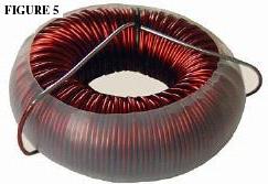
The donut shaped gathering coil surrounds the magnet and Tesla Coil Cone structure. The two leads that come off the copper gathering coil are connected to the flyback circuit. Figure 5 shows an image of the copper gathering coil.
Each magnet and its characteristics are different and therefore a sync generator is used to first determine the prepared magnets harmonic thresholds. The BK Precision sync generator model number 4011A, 5MHz
Function Generator was used for determining magnetic configuration of harmonic frequencies. For electrical testing, a Protek Digital Multimeter model number 506 was used. Each magnet has a natural calibration and therefore it is advised that the magnet be tested first prior to customizing an electronic flyback circuit.
It is not needed to go into great detail about the electronic flyback circuit as this is simply a circuit that duplicates the sync pulse generators waveform. A secondary circuit is used in the final version that strips off excess electricity that is to be used for external requirements and at the same time strips off electricity that is used to perpetuate the pulse generator.
Each Tesla Coil Cone has two leads that connect to the flyback circuit. Varying configurations can be used such as powering each Tesla Coil Cone individually however for this example one Sync generator is connected to the 8 Tesla Coil Cone leads on the one side of the magnet. The other 8 Tesla Coil Leads are connected to a second sync generator.
Various timings, delays and pulses can be used on a sync generator however the sync generator is set to square a wave form output, Range 5M, not inverted, DC Offset on, Duty cycle high and output level high.
Both sync generators are set to be as close to offset as possible, halving the square wave output in a harmonic pattern.
Connecting the Multimeter to the two wire leads from the coil and testing for the output voltage while fine tuning the synch generators will result in a voltage peak on the connected multimeter.
For a custom designed flyback circuit a programmable chip (PIC) is used to generate the harmonic timings that are delivered to the Tesla Coil Cones. One skilled in the art will realize that there are many methods to produce and deliver a square wave harmonic pulse to the Tesla Coil Cones, without detracting from the scope or concept of this invention.
The operational foundation of this patent is that the Tesla Coil Cones harmonic pulses cause an expansion and contraction of the magnets Input and Output ports. These low voltage harmonic pulses cause the magnetic field of the magnet to wobble and when used in combination with a gathering coil, create more electricity than the requirements of the flyback circuit and the Tesla Coil Cones.
In combination the previous is a method and apparatus that produces excess alternating electricity in the form of a tunable round wave output for use with electricity requirements.
# BRIEF DESCRIPTION OF DRAWINGS:
These and other objects and features of the present invention will become apparent from the following description, viewed in conjunction with the attached drawings. Through these drawings, like parts are designated by like reference numbers:
FIGURE 1 is an illustration of the side view of the magnet and conical hole positions, described in accordance with the invention herein.
FIGURE 2 is an illustration of the side view of the magnet and conical hole positions including the Tesla Coil Cones placed in the conical holes, described in accordance with the invention herein.
FIGURE 3 is an illustration of the cross sectional view of Tesla Coil Cones and relative positions, described in accordance with the invention herein.
FIGURE 4 is an illustration of the cross sectional view of magnet showing energy flow between the Input and Output ports and the patterns generated from this circulation, described in accordance with the invention herein.
FIGURE 5 is an image of the Copper gathering coil, described in accordance with the invention herein.
FIGURE 6 is two side views of a magnet, Tesla Coil Cones in combination with a silver wire coil described in accordance with the invention herein.
FIGURE 7 shows how the magnetic field wobbles when the left and right side Tesla Coil Cones are alternated between on and off in accordance with the invention herein.
# DETAILED DESCRIPTION OF THE PREFERRED EMBODIMENT:
The preferred embodiment, A method and apparatus that produces excess alternating electricity in the form of a tunable round wave output for use with electricity requirements, will now be described with reference to FIGURE 1, FIGURE 2, FIGURE 3, FIGURE 4, FIGURE 5, FIGURE 6 and FIGURE 7.
The invention herein uses a typical neodymium magnet however it does have some manufactured features that allow its have indentations in its side and still maintain most of its desired and typical magnetic field.
FIGURE 1 shows a neodymium magnet that is 2 inches by 2 inches by 6 inches. Due to the 2D view, FIGURE 1 also shows the placements of 4 conical holes however the magnet has 8 conical holes. The magnet shown has its north and south poles at the longest end. Each hole is positioned 1/3 along the length of the north-south axis. Each hole is center positioned 1/8th inch less than the center width of the magnet.
The diameter of the conical holes depends on the size of the magnet. FIGURE 1 has the conical hole diameter at the magnet surface of ¼ inch. Each conical hole measures 1 7/8th inch deep from the surface to the conical hole point. Each conical hole is tapered from ¼ inch on the outside of the magnet to 1/8 of an inch at its deepest reach into the magnet. Figure 1 graphically details this example of the described magnets dimensions and conical positions.
FIGURE 2 shows small Tesla Coils in the shape of cones are placed inside the conical holes. Each Tesla Coil Cone has a protruding end that allows for coiled wire which is used to ramp up the electric field that is generated by the Tesla Coil Cone. Each of the 8 Tesla Coil Cones is similar in size and materials. Each Cone case is hollow cardboard with its exterior shellacked. Each cone measures 2 3/8th inches long. This allows for ½ inch that protrudes outside of the conical hole. A single layer of 30 gauge copper coated wire is wound around each Tesla Coil cone. Each Tesla Coil Cone has 82 full single wraps around the exterior of the conical case. Various other wire compounds can be used such as silver, gold, or conductive alloys with various results. Various wire gages wrapped around the Tesla Coil Cones can be used with varying results
Each tip of the Tesla Coil Cones is made of iron. This iron tip has two purposes one purpose is that it acts as a collector of electrical field charges and two, it acts as a swing magnet that rotates its magnetic field as the electrical charge is applied and discharged. The iron tip is 1/8th of an inch long. Once positioned, the apposing tips of the Tesla Coil Cones have ¼ inch gaps. Figure 2 graphically details the Tesla Coil Cones herein described placed in the conical holes described in FIGURE 1.
FIGURE 3 illustrates the Tesla Coil Cones that are positioned in the conical holes that are attached to the magnet illustrated in FIGURE 1.
A magnetic field is not generated by an iron bar, but rather the iron bar is the carrier of the magnetic field.
Also as mentioned prior, this magnetic field has what is best described as an Input and an Output, for lack of other describable words. The magnetic field flows from the magnetic port Output and back into the magnetic port Input. FIGURE 4 illustrates this energy circulation process between the Input and Output ports.
A donut shaped copper gathering coil is used as a medium for the electric field to move within. This donut shaped gathering coil in this design uses copper coated 12 gage wire. As an alternate to copper wire, silver, gold or platinum wire can be used. Any gage wire can be used and any conductive wire can be used with varying degrees of success. Further, various coil designs can be used with varying degrees of results. The donut shaped gathering coil surrounds the magnet and Tesla Coil Cone structure. The two leads that come off the copper gathering coil are connected to the flyback circuit. FIGURE 5 and FIGURE 6 show an image of the copper gathering coil and cross sectional views respectively.
FIGURE 7 shows how the magnetic field wobbles when the left and right side Tesla Coil Cones are alternated between on and off using a round wave input to the Tesla Coil Cones.
# THE EMBODIMENTS OF THE INVENTION IN WHICH AN EXCLUSIVE PROPERTY OR PRIVILEGE IS CLAIMED ARE DEFINED AS FOLLOWS
A method and apparatus that produces excess alternating electricity in the form of a tunable round wave output for use with electricity requirements.
I CLAIM: A method and apparatus that uses a harmonic sync generating system to wobble a magnetic field.
I CLAIM: A method and apparatus that focuses the electric fields generated by a Tesla Coil by way of a Conical shape.
I CLAIM: A method and apparatus that generates focused electric fields that are harmonically pulsed to cause a magnetic field to wobble.
I CLAIM: A method and apparatus that pinpoints specific areas to place harmonic and focused harmonic electric fields on a magnet that are used to wobble a magnetic field.
I CLAIM: The realization that the magnetic field is not produced by the magnet but rather that the magnetic field is a result of various energy movements that are being altered in frequency by the magnet.
I CLAIM: Every future patent and technology that utilizes this or any alternate to this patent to be hereafter freeware.
IN COMBINATION IS: A method and apparatus that produces excess alternating electricity in the form of a tunable round wave output for use with electricity requirements.
A note about the following drawings. As this patent is not being filed with any patent office, to make it clearer to the reader, cryptic numerals are not used in reference to the following drawings.
Apposing conical holes are also similarly positioned on the magnets opposite sides.
Magnet showing energy flow between the Input and Output ports and the patterns generated from this circulation.
Image of the Copper gathering coil.