## The Overunity parametric transformer, by Fred B. Epps, fepps@halcyon.com, Created on 7 July 97 http://jnaudin.free.fr/html/paraform.htm
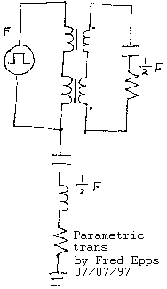
Here is my design for a parametric transformer that has overunity characteristics. Although it is a simple circuit, it is the result of a great deal of research. It is based on an earlier design built by Jean-Louis Naudin which is on his website at: varind40 http://jnaudin.free.fr/html/varind40.htm
My new design eliminates the drawbacks of the earlier one and is based on a clearer understanding of the principles involved. For those of you who are new to the world of “parametrics” I will briefly explain the principles behind these devices before launching into a detailed description of how they can be overunity. To illlustrate these principles I will quote from a paper which greatly influenced my development of this machine, “On the Parametric Excitation Of Electric Oscillations” (1)
“As we have shown earlier, starting from energy considerations it is easy to account for the physical aspects of the excitation of oscillations by periodic (stepwise) variation of the capacitance of an oscillatory system not containing any explicit sources of magnetic or electric fields. We shall briefly repeat this argument for the case of variation of self-inductance. Suppose that a current i is flowing in an oscillatory system consisting of a capacitance C, ohmic resistance R, and self inductance L, at some instant of time which we shall take as the starting instant. At this moment we change L by dL, which is equivalent to increasing the energy by 1/2 dLi^2.
The system is now left to itself. After a time equal to 1/4 of the period of the tuned frequency of the system, all of the energy transforms from magnetic to electrostatic. At this moment, when the current falls to zero, we return the self-induction to its original value, which can evidently be done without expending work, and again we leave the system alone. After the next 1/4 period of resonance oscillations the electrostatic energy transforms fully into magnetic energy and we can begin a new cycle of variation of L.
If the energy put in at the beginning of the cycle exceeds that lost during the cycle, i.e., if 1/2 dLi^2 > 1/2Ri^2 (T/2)
or dL/L > e
where e is the logarithmic decrement of the natural oscillations of the system, then the current will be larger at the end of each cycle than at the beginning.
Thus, repeating these cycles, i.e. changing L with a frequency twice the mean resonance frequency of the system in such a way that dL/L > e
we can excite oscillations in the system without any EMF acting on it, no matter how small the initial charge.
Even in the absence of the practically always present random inductions (due to power transmission lines, terrestrial magnetic fields, atmospheric charges) we can in principle always find “random charges” in the circuit on account of statistical fluctuations.”
The question is, is it possible to use less energy to change the inductance or capacitance than is generated in the resonant circuit? I believe it is, in both inductive and capacitive cases. Because of the limitations in the art of capacitors, the inductive case has more potential for higher power outputs. A parametric transformer was patented by Leslie Wanless in 1971.
This transformer uses the varying magnetic field of the primary to periodically change the L of the secondary, which is part of a resonant circuit as in the paper quoted above. Standard EM induction is eliminated by use of windings at right angles. Since the primary is excited by an AC current at F the inductance varies at 2F, because there are two magnetic field peaks in each cycle, one at the positive and one at the negative voltage peaks. Since the output current is at half the frequency of the parametric variation as described in the above paper, the output current is half of 2F, or the orginal input frequency F.
This is important for reasons to be explained shortly. This form of parametric transformer is not an overunity device because it is entirely reciprocal: the magnetic field of the SECONDARY current at F induces an inductive variation in the PRIMARY at 2F, causing a parametric current at F which opposes the input current. The inputs and outputs of such a transformer can be reversed with no change in operation IF the primary is part of a resonant circuit at frequency F.
I understand that this is complicated and appears to be going nowhere, but I hope that at least some of you will bear with me. Examine the circuit shown on Jean-Louis’ web page. The special variable inductor is driven by a CMOS square wave generator with, of course, a DC output. Jean-Louis has reported to me that loading the secondary of this circuit did not load the primary. This was puzzling to me because there should have been SOME loading of the primary, even with the special core materials used to minimize such loading.
The explanation is simple and is in two parts:
1) The input circuit is nonresonant. Although the output current’s magnetic field still varies the inductance of the primary, it cannot cause a parametric current opposing the primary current because there is no capacitor in parallel across the input so that this opposing currnet can build up. It dies in every cycle. This does not eliminate but only minimizes the “parametric back EMF”, however.
2) More importantly, Jean-Louis used a DC signal for the input. Recall that a parametric current flows at half the frequency of variation of the parameter. In the Wanless transformer, there are two inductance peaks in every primary cycle at input frequency F, leading to an output current at this same frequency F, leading to a parametric back reaction at F which loads the primary. But in Jean-Louis’s circuit, the input is DC so there is only one inductance peak per cycle at F. As a result the output frequency is 1/2F, and the back reaction is at 1/2F. In Jean-Louis’s circuit this reduces the loading to imperceptible levels, but does not eliminate it. The combination of these two factors makes the loading of the primary “invisible” within the possible range of secondary loads for such a device.
I have designed a transformer which uses these principles to go overunity. Please refer to the GIF included with this post. The inductors shown consist of two specially-wound standard laminated transformer cores. The two primaries and the two secondaries are each in series but the secondaries are wound in opposite directions. It has been shown that this is the most efficient method of eliminating EM induction from the operation of parametric transformers (2) as the EMFs in the secondaries cancel out and do not produce a back EMF in the primary. The driver is a low-current square wave generator such as the CMOS circuit used by Jean-Louis, operated at frequency F.
The output circuit consists of a load and a capacitor such that the resonance is at 1/2 F. This output is an AC sine wave, despite the DC square wave input. This can be seen from examining the output waveforms in the Varind 4 tests. According to the principles we have discussed, a parametric back reaction waveform develops in the primary at 1/2F because there are two inductance peaks in every cycle of the output.
Because the primary frequency and the back reaction frequency are different, it is possible to completely eliminate the back reaction’s effect on the primary and recover the energy of the back reaction using a simple series-resonant tap as shown in the GIF. The energy flowing through the primary that would normally partially cancel the input voltage is now used to drive a second load.
In summation, although it may or may not be possible to eliminate back EMF in a normal induction motor or transformer it is certainly possible to eliminate it in certain parametric arrangements because the input and output frequencies can be made to be different, something which can never occur in a normal transformer, where the input frequency and the output frequency are always the same.
Since there is very little loading of the input in the circuit I describe, many of these devices can be operated in parallel from the same driver, taking care to reduce series resistance as much as possible.
I will be interested in comments and even more interested in tests made on devices such as the one I’ve described. Fred Epps
1) “On The Parametric Excitation Of Electric Oscillations’ by L.I. Mandelshtam and N.D. Papaleksi Zhurnal Teknicheskvoy Fiziki, 4, n.1, p. 5-29, translated for Lawrence Livermore Laboratories, Feb 1968
2) “Comparison Of Orthogonal- And Parallel- Flux Variable Inductors” by Z. H. Meiksin IEEE Transactions On Industry Applications, V. IA-10, n.3, May/June 1974
## A Switched bifilar parametric circuit, by Fred B. Epps, fepps@halcyon.com, Created on 18 August 97 http://jnaudin.free.fr/html/parabifc.htm
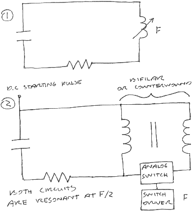
Hi All! Although the study of scalar effects is inherently interesting and valuable, I don’t believe it is necessary to invoke scalar waves to demonstrate overunity with a device similar to the TEP. Consider circuit 1 below. This is the basic parametric inductive circuit. It is known (maybe not WELL known) that if the inductance in this circuit is varied periodically at freq F, an oscillating current will develop at F/2.
It is generally believed that the energy needed to vary the inductance is exactly the same as the energy in the current. For some time on the list I have questioned whether there is any inherent connection between these two values.
Now look at circuit 2. A bifilar or counterwound coil on a ferrite core has been substituted for the variable inductor in circuit 1. An analog switch driven by a square wave generator has been interposed between the two windings. The result is that for half a cycle any current passing through the circuit goes through one side of the bifilar inductor and for the other half the current goes through both sides. The result is that the total inductance goes from a high value to a very low value. This varying inductance operates in the same way as the variable inductance in circuit 1 and a current builds. The value of this current is based on depth of variation of the inductance, and the load resistance. Since the variation is high, the current will be high. On the other hand the energy needed to switch this current through the second half of the inductor is small.
The obvious result is a much larger output than input.
I am not a builder by nature, but this is a simple circuit that I could build. Unfortunately I don’t have any way of testing it once I’ve built it (no scope etc.) I would appreciate it if one of you electronics wizards could put it together and test it out. There are a few more details that would need to be discussed so contact me.
The original idea for this circuit is based on a concept of Jean-Louis Naudin’s. I also want to thank Stuart Rae for his suggestions and help.
## A “Large Coil” parametric circuit , by Fred B. Epps, fepps@halcyon.com, Created on 23 August 97 http://jnaudin.free.fr/html/largcoil.htm
Hi Folks! In the spirit of others who have built or discussed overunity devices using large coils, here’s mine. It is a parametric transformer that uses large coils to create a large change in L in ferrite or metglas cores which is tapped by a parametric output circuit for power. According to Stefan Hartmann’s understanding of the Newman motor, this could be called a Newman transformer, understanding of course that Mr. Newman’s explanation for his motor is totally different. In the attachment you will see three identical pairs of coils. (The number of pairs is arbitrary.) The primary circuit consists of parallel windings across all six coils in a resonant tank circuit driven by a low-power oscillator. These windings have many turns and are individually high inductance, although because of the parallel arrangement the L of the primary tank as a whole is relatively low. The secondary consists of much smaller windings in a series resonant circuit with the load. Every other secondary winding is in reverse direction so that the sum EMF generated by induction is zero. There is no back EMF because there is no forward EMF– the energy transfer is entirely through the changing inductance.
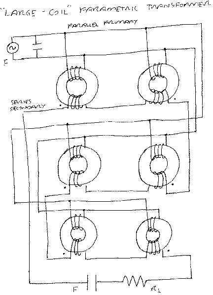
The cores consist of manganese zinc ferrite or other magnetic material with a high variation of mu with applied field. The entire core assembly may be biased with an orthogonal permanent magnet field to put the cores at the knee of their B/H curve, to maximize change of L with changing primary field.
How it works: it is conventional that a large coil generates a large magnetic field, thus the fields in the primary coils are large for a given current. Since the core materials are set up so that even a small variation in field causes a large variation in L, it takes a very small oscillating current in the primary to cause large changes in the inductance of the cores.
The energy in a parametric circuit is strictly dependent on the variation of inductance in that circuit. This also is conventional, although not as widely known. Therefore the current in the resonant output circuit will be high. Small current in, large current out…it’s as simple as that.
Actually it’s not as simple as that– it never is 🙂 The large current flowing through the output circuit does load the primary to a certain extent by changing the inductance of the cores in opposition to the primary’s effect. But this effect is minimized by the large difference between the size of the secondary and primary coils. And the primary current is so small that even if it were to double because of the loading it would still be small compared to the output. (Keep in mind that the usual voltage/winding equation in transformers does not apply here, since there is no induction).
I will be interested in comments, especially critical ones.
## The TEP is Parametric !, by Fred B. Epps, fepps@halcyon.com, Created on 01 September 97 http://jnaudin.free.fr/html/paratep.htm
Hi Jean-louis and others in the TEP team!
Your new “nonreciprocal” experiments http://jnaudin.free.fr/html/tep4nrcp.htm completely corroborate my new theory on TEP operation.
The key to my theory is a statement made by someone on the list to the effect that when L3 is “on” the system as a whole is NOT noninductive. L3 supports one of the windings of the TEP coil so that it has a finite inductance. When L3 is switched “off” the TEP coil returns to its natural noninductive state.
The L thus goes back and forth between a value typical of a usual coil to the very low value of a bifilar coil. This provides the mechanism of parametric pumping according to the formula E= 1/2Li^2 (as the L goes to zero the energy in the coil must expand in order to maintain conservation laws).
The TEP is the fulfillment of my dream of a parametric energy source. It is a better scheme than my “switched bifilar” device, which can be forgotten. The TEP needs only a few small modifications and it will be overunity to an extreme degree!
Since the change in L is very large, the magnification of energy is TREMENDOUS. The energy seen in the TEP output does not derive from the L3 coil at all, but simply comes from the amplification of small noise voltages in the TEP coil. These voltages are probably in the milivolt if not microvolt range so the parametric amplification is at least 10,000 times for the circuit describe by you.
Jean-louis, operating this circuit in DC form means you are running it in its LEAST efficient form! If the output circuit is resonant, the amplification will be applied to the voltage of the previous cycle and the energy gain will be ASTRONOMICAL! I am ABSOLUTELY sure of this! It will be necessary to put resistive heating elements in the circuit to dissipate energy and high current wire will be needed!
It is true that the input must be a DC pulse because of how the device operates (but even that limitation can be overcome–see below). But it is not true that the OUTPUT circuit must be gated by diodes. No matter which way the current flows in a resonant form of your device, the L3 coil will support one field over the other and the noninductive coil becomes inductive, which is all that is necessary for the amplification to occur. Drawing 1 in the GIF shows the new design for the TEP circuit– it is obvious.
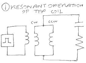
(I have drawn the TEP coil as a counterwound coil rather than a folded back coil because it makes the energy flow easier to see– for me at least– but the principle is the same.)
The TEP is completely nonreciprocal because not only is there no inductive output from the TEP coil, the amplification occurs when L3 is turned OFF. There is no way that the voltage generated in the TEP coil can affect the off state of the driver!
If TWO TEP coils are built, then the INPUT circuit can also be made resonant by the simple expedient of making it a tank circuit and passing the positive and negative halves of the sine wave through two gated branches, each of which contains a TEP coil. This is shown in drawing 2.
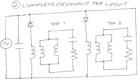
[I forgot to put in the “CW” and “CCW” notations in this picture]. This will result in a little loading of the input because the output L will be changing as the input is still “on”, but this disadvantage will be compensated by the much lower energy needed to maintain the input.
There are other factors. Inclusion of a LINEAR magnetic material in the TEP core will increase the parametric amplification even more because the depth of variation of the L in each cycle will be increased greatly. I suggest a LINEAR material so that the output waveform will still be a typical parametric sine, ready for the power outlet 🙂
Also– the “overefficiency” of the circuit is limited by the intensity of the magnetic field generated by L3, since it must be equal to the field generated by one of the branches of the TEP according to my theory. “Large coil” techniques could be used for this purpose.
The overunity nature of this device arises from the cancellation of the fields in the TEP coil. It is possible that “scalars” are generated by this cancellation, but the cancellation itself allows for the change of inductance without doing work. The question of HOW the magnetic field or inductance is cancelled brings in the whole hornet’s nest of scalar theory, and undoubtably leads to the answer to the question “where is the energy coming from?”
## The Time Energy Pump project, created on 10/12/97 – JLN Labs – last update on 10/12/97, http://jnaudin.free.fr/html/tep62par.htm
THE PARAMETRIC TESTS
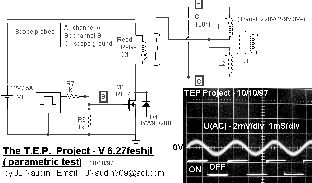
Fred Epps comments :
Suj : Re: TEP 6.24-5-6-7FESHJL – TESTS RESULTS ; Date : 10/10/1997 13:01:17; From: fepps@halcyon.com (Fred Epps)
Hi Jean-louis and all Teppers! Good work! Thanks for doing these tests.
To clarify, the transformer core was necessary and the inductances of the cores are additive– that is, when the switch is open the inductance is L1+L2, and when it is closed the inductance is just L1.
Very interesting results!!! The necessity that there be a core, as well as the pure sine waveform, indicate a pure parametric resonance. I had thought that we would see something with the air core, but we didn’t. Stefan was right about using a transformer.
He and Dieter were also correct about simply adding and subtracting inductance through a variable resistance (switch).
I consider this a very significant result, although the energy output is small. This experiment demonstrates that energy can be generated purely by switching, with no other energy output. There can be no mistaking this result, as it is clear that there is no energy input into the tank. This result is totally contrary to known electrical science, which states clearly that switching itself cannot add energy to a circuit.
I hope that you are not fooled by the small power output into believing this is a minor test. It is an avenue into a whole NEW area of development.
The energy output of this sort of circuit depends on the difference between the total inductance L1+L2 and the starting inductance L1. The larger this difference the larger the output, with no theoretical limit that I am aware of.
I think you can see the implications of this. In addition the L1 needs to be somewhat large for a useful circuit.
There is also no way to tell at this point whether the coils need to be magnetically coupled or not. This is a key point for the technical development of this principle. There is also the effects of various core materisl which always become important in parametric circuits. I will be working on experiments to test these other aspects.
Thanks again, Jean-louis, for doing these many tests for us. I find the results of this particular test to be unequivocal, thought-provoking and inspiring!