## Free electric energy generator – The ReneRator http://www.zpenergy.com/modules.php?name=News&file=article&sid=2087
Posted on Sunday, October 22, 2006 @ 20:18:06 PDT by vlad ; Anonymous writes:

original picture: http://i125.photobucket.com/albums/p51/renerator/freeenergy.jpg
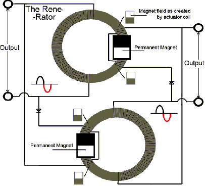
Every second wave, marked red, coming from the output coils is the actuator pulse for the “input” coils to block the magnetic field of the permanent magnets. The permanent magnetic field retracts from the core inducing a current flow in the output coils. After the input “pulse” is gone, the permanent magnet will restore the magnetic field in the core, causing a “back-emf” in the output coils.
(Added later to this post) 10/25/06 – ReneRator copied 1871 US Patent ( from KeelyNet.com http://www.keelynet.com/ news ) –

(Thanks to James Tabor for bringing this to our attention. – JWD)
Regarding the 10/24/06 free energy circuit posted at zpenergy.com, reader James Tabor noticed a distinct similarity to an almost identical circuit patented in 1871 by Daniel Cook as #119,825.
In the patent, Cook writes; “Improvement in Induction Coils – My invention relates to the combination of two or more simple or compound helices and iron cores or magnets in such a manner as to produce a constant electric current without the aid of a galvanic battery…The iron core A may be a solid bar or a bundle of iron wire…Helices alone with large quantities of wire will produce similar results…
A ribbon spiral may be substituted for the secondary helix, say of three, six, twelve, or twenty-four inches in width and of any convenient length, but always of sufficient length to raise the tension of its terminal current to a degree necessary to reproduce itself by its action on the primary helix…
In the use of compound helices it is important that the secondary coil should be wound on in the same direction as the primary coil, and that the secondary poles or wires should connect to the OPPOSITE poles of the primary coil B…
The action will then be as follows; The terminal secondary current of the secondary helix C will circulate through the opposite primary coil B while at the same instant a terminal secondary current from the primary helix B will be developed and circulate through the opposite secondary helix C, both currents flowing in the same direction in the opposite helices B C, and produce a combined magnetic action upon the iron bar A in the center;
the opposing intial secondary currents of the two helices B C being overpowered do not manifest themselves in the main circuit D of the battery, there being eight distinct currents developed in the action of one entire circuit of two pairs of helices, two terminal and two initial secondary currents to each pair of helices, the four initial secondaries constantly opposing the circulation of the four terminal secondary currents,;
but the initial secondaries being of much lower tension and less in quantity than the terminal secondary are consumed or taken up by the terminal, leaving a sufficient surplus terminal to overcome the resistance of the primary wire and charge the bar A to a degree necessary to reproduce itself in an opposite secondary coil.
By this means a constant current is kept up in the several helices…The mode of producing or starting the action in the helices consists in the use of a steel or electromagnet, or a helix, around one of the helices, and causing a secondary current in the enclosed helix by means of a battery current in the outer one; the action then in either the simple or compound helices increases in quantity to the maximum capacity of the wires to conduct with the existing tension of the current.
If, now, the circuit is broken the current instantly ceases, and can only be restored by the same means that it was first produced; hence to alow the use of the main circuit for common purposes I introduce a rheostat or a resistance of any kind into the circuit, so that a small portion of the current only will flow along the resistance, by which means the action in the helices is feebly maintained when the main circuit is broken, and instantly restored when it is closed to its full force…
The alternate changes of the iron cores or magnets may be used for producing electro-magnetic motion, or motion to a wheel of any suitable device…”
## From Patrick Kelly files http://panacea-bocaf.org/files/patrickkelly/Start.html
Daniel Cook: in 1871, he obtained USP 118,825 for ‘An Improvement in Induction Coils’.
it is by no means obvious how the device described could possibly operate, but as I have no direct evidence that it does not or can not operate, it is shown here. It is a very simple device which could be interresting to test, especially as it does not involve any electronics or complicated construction. The patent can be summarised as follows:
My invention relates to the combination of two or more, simple or compound, helical coils with iron cores or magnets, in such a manner as to produce a constant electric current without the aid of a battery.
… In carrying my invention, I do not confine myself to any particular mode of coil construction or to any particular size of wire, observing only that the quantity of wire in the various coils must be sufficient to produce the required result; also, the material used to insulate the wires must be suitable for producing the required result. However, I generally prefer to use the same size of wire in the construction of both simple and compound coils.
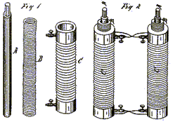
When constructing simple coils, to produce the required voltage and current, it is desirable to use a long iron core as shown as A in Fig.1.
This iron core may be two, three or even six feet in length, and two, three or more inches in diameter. The coil should be wound from good quality copper wire, insulated with silk or shellac. The iron core A may be a solid bar or a bundle of separate wires, the latter giving better results and providing more current for any given wire diameter. While the wire may be fine or coarse, I prefer to use No 16 or even heavier wire, as the power output is in proportion to the length and diameter of the wire.
When using compound coils, it is preferable in some cases to use a small wire, say No 30 or even less, for the primary coil, and No 16 or even larger for the secondary coil. With this combination, the initial secondary current of the primary coil being very small in comparison to the terminal secondary current of the secondary coil, offers little resistance to the terminal secondary, hence a quicker action is obtained.
Alternatively, the primary coil may be of uninsulated wire coiled into a solid helix, being insulated only between the coils, in which case there is little or no opposing initial secondary current.
Helically wound coils alone with largequantities of wire will produce similar results. A ribbon spiral may be substituted for the secondary coil C, say, of three, six, twelve or twenty-four inches in width and any convenient length, but always of sufficient length to raise its output current to the level necessary to sustain itself through its action on the primary coil B. In the use of compound coils, it is important that the secondary coils should be wound in the same direction as the primary coil, and the primary and secondary coils be cross-connected as shown in Fig.2.
The action will then be as follows:
The secondary current of the secondary coil C, will circulate through the opposite primary coil B, while at the same instant, a secondary current from the primary coil B will be genrated and circulate through the opposite secondary coil C, both currents flowing in the same direction in the opposite coils B and C, producing a combined magnetic action on the iron core A in the centre. The opposing initial secondary currents of the two coils B and C being overpowered, do not show in the main circuit D of the device, there being eight distinct currents developed in the action of one entire circuit of the two pairs of coils, two terminal and two initial secondary currents to each pair of coils, the four initial secondaries constantly opposing the circulation of the four terminal secondary currents, but the initial secondaries being of much lower voltage and current than those of the terminal secondary, are overcome, leaving a sufficient surplus terminal power to overcome the resistance of the primary wire and charge the bar A to the degree needed to reproduce itself in the opposite secondary coil. By this means, a constant current is kept flowing in all of the coils.
These coils may be constructed using 500 feet to 1,000 feet or more for each of the primary and secondary coils. The longer, and better insulated the wire, the greater is the power obtained from the device. The larger the wire diameter, the greater the current obtained.
If only single coils are to be used, it is preferable to have a wire length of 1,000 feet or more in each coil. The action is the same as with the compound coils, but only four currents are produced: two initial and two terminal currents, the latter flowing constantly in the same direction – in effect, there being only one current in the same direction.
The action in the coils may be started by using a permanent magnet, an electromagnet or by pulsing an extra coil wound around the outside of one of the coils of the device. If the load circuit is broken for any reason, the current stops immediately. It is then necessary to perform the start-up procedure again to get the device restarted. This can be overcome by permanently connecting a resistor across the terminal of the load so that if the load circuit is broken, the device can continue under very much reduced current until the load is restored. By this means, the device becomes the direct equivalent of a battery.
A rheostat D may be introduced into the main circuit to limit the current and prevent the overheating of the coils through the drawing of excessive amounts of current. The iron cores may also be used for producing electromagnetic motion when the device is operating.