(page created for November 2007 update)
Peter Lindemann posts on Energetic Forum about the Attraction Motor Concept
From http://www.energeticforum.com/renewable-energy/271-electric-motor-secrets.html
Page 11 of the thread
# 301 ; by Jetijs, Member, 11-05-2007, 02:29 AM
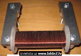
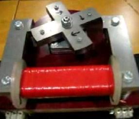
Ok, I have been busy today and the motor is finally finished, here’s the startor ready for coil winding:
The coil winding process was the hardest part, because I did this with hands. The startor is heavy and with each turn of wire it became even heavier. I wound three strands of gauge 21 wire. There are about 250 turns ( I lost the count in the winding process which took me about 2 hours). Each strand has a resistance of 1.7 Ohms.
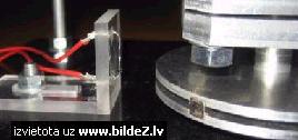
Now as for the reedswich. At first I tried to mount the reedswitch to the plexiglass holder horizontally, but that did not work well, the duty cycle was bad, about 70% on time and 30% off time at best.
Then I mounted the reedswitch to the holder vertically. This was a lot better, now I could easily adjust the timing as needed.
I had to make a second plywood base plate so I have a place to mount the reedswitch. Heres how it looks like:
And now pictures of the whole thing:
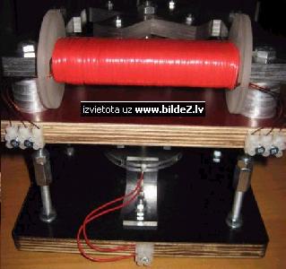
I have not adjusted the timings now, I just tested if the adjustment works. Now I need to solder the circuit. Peter I think you missed my previous question:
# 303 ; by nali2001, Member, 11-05-2007, 08:17 AM ; Motor
Hi there Bob an’all. Well I have found that some (new) ball bearing have radial play (super very minor though) and also axial play (not at all that minor) So just to be safe I used roller bearings since you can adjust them.
A sheet of paper is actually more in the range of 0.05 to 0.08mm At the moment my system uses 0.07mm and I have seen that it is very possible to go even beyond that, IF your stator is actually that exact also. I use a deviation from the original attraction motor design. Since I use normal induction motor stators and these are of course professionally made and so very precise. The rotor is machined 0.5mm to big and when it is finished I machine the last outer diameter of the rotor and axle section for the bearings in one pass. (Without taking it out of the chuck) So it is maximum/high precision.
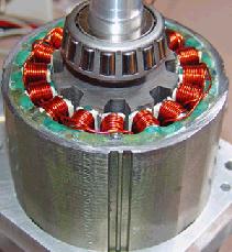
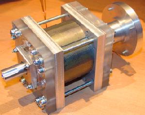
Finally finished wiring the stator. Had tons of problems with the insulation for the coils. Like ten times somewhere in the wrapping process I discovered a short to the core. Finally settled for cloth-epoxy insulation since multiple layers of tape does not cut it. Not much room in there also.The wiring is low inductance. Each coil (my stator has two) is 1.1 ohm 0.8mm wire. Im lucky that this stator design must have very short pulses since I=v/r so my thing will be eating like 10 amps or 20amps at 24v on full on. Funny if you think about it. The rotor has 8 fingers and the stator has 16 so that means in each revolution there are 128 attraction places.
Well here are some pictures. The wheel at the back is for the opto trigger stuff. (Still had that wheel from another machine). Regards, Steven
# 304 ; by Peter Lindemann, Senior Member, 11-05-2007, 10:36 AM ; Jetijs and Steven
Jetijs, Without seeing your exact schematic circuit, including the output section, I don’t know why you are seeing the behavior you report. I know that John and I ran numerous tests with parallel coils and found that parallel coils triggered by a single transistor tend to discharge INTO each other rather than out through the output section. This slows down the field collapse and reduces the amount of recoverable energy.
Steven, Your motor is looking very good. The torque should be excellent for input power. The recoverable energy will depend on your switch timing and recovery circuits. I know I speak for many people on this forum who are very interested in your test results. We all look forward to your motor performing extremely well.
# 305 ; by lighty, Member, 11-05-2007, 11:52 AM
Quote : Originally Posted by Peter Lindemann : I know that John and I ran numerous tests with parallel coils and found that parallel coils triggered by a single transistor tend to discharge INTO each other rather than out through the output section. This slows down the field collapse and reduces the amount of recoverable energy.
End of quote.
In other words Litz wire should be avoided for winding the energizer coil?
# 307 ; by Jetijs, Member, 11-06-2007, 03:13 AM
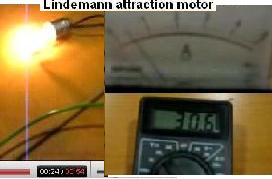
Ok Peter, I did some test runs on my motor. The circuit is exactly like in your youtube videos except that I used the 2N3055 transistor and the nominals of the resistors are 200 Ohms (R1) and 196 Ohms (R2). I used only one of the three strands. At first I set the voltage of my variac to 30V and hooked up an analog amp meter. I shorted the output on the first test and got 1.1A current draw and 655 RPM. Next I attached 12v light bulb to the output, now the current draw reduced to exactly 0.4A and the RPM increased to 920. This time I noticed the neon bulb doing some flashes occasionally. It flashed a little bit mode when the motor was starting to gain speed, at the full speed the neon flashed only very few times and dimly. I suppose this is because the bulb can not take all of the charge and what is left goes to the neon. But the light bulb was shining very brightly. For the last test I attached a discharged 1.3Ah lead acid battery to the output. This time I did not see any decrease in current draw, but the RPM went up a little bit to 956. Also the neon bulb was not flashing at all, that means the battery absorbs the recycled energy very well. When I started this last test, the battery voltage increased from 11.60 to 12.24 in some seconds, then it settled down and continued to increase slower. So the results:
Test 1. Voltage 30V Current draw 1.1A RPM 655
Test 2. Voltage 30V Current draw 0.4A RPM 920
Test 3. Voltage 30V Current draw 0.4A RPM 956
And all this with only one strand of gauge 21 wire
Will do some more testing, but I must change the bearings first, because there is some friction in them and that makes the motor noisy and reduce the performance.
# 308 ; by Jan H, Junior Member, 11-06-2007, 03:29 AM
…
Bobo, About the air gap, you are right when you say its hard to get it very small. But the way I imagine it is like having two magnets attract eachother, when they get really close, lets say >1mm the force of them pulling together increases exponentially. I THINK that is what makes the need for a small air gap.
# 309 ; by Peter Lindemann, Senior Member, 11-06-2007, 04:15 AM ; You get the GOLD STAR!!!
Jetijs, Very, Very Good. Solve your bearing issues and resume your tests. As you add all three strands to the power side (each with their own transistor) your input should triple to about 1.2A. The output to the 12 volt battery will be over 2.0A, so you may want a larger battery to charge than your little 1.2AH one.
Also, you will be able to trigger all three transistors from the single magnetic reed, but you will need to balance the branches to each transistor base. Keep up the great work!
# 310 ; by Jetijs, Member, 11-06-2007, 04:48 AM
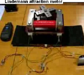
I uploaded a short video on youtube, you can watch it here:
YouTube – Lindemann attraction motor http://www.youtube.com/watch?v=1QEYH1IbRP4
Peter, I don’t understand this balancing of the branches. Can you please explain what you mean? Thank you
# Pictures from the video linked above by Jetjis
YouTube – Lindemann attraction motor http://www.youtube.com/watch?v=1QEYH1IbRP4
# 311 ; by lighty, Member, 11-06-2007, 05:00 AM
@Jetijs, I noticed a strange vibrating sound when your motor is in operation. Something is not balanced or not centered correctly or with low enough tolerance.
Did you consider using another base plate and another bearing so that you can have a 2 point shaft support? You can then use self-centering axial-radial bearing at one side to compensate for eventual lateral movements. I have had experience building powerful motor from scratch and one point support of shaft is simply too unreliable for the forces involved. Especially with pulse motors. Nevertheless – a GREAT work pal!
# 314 ; by Jetijs, Member, 11-06-2007, 05:49 AM
That noise is coming from the bearings, I am sure about this, because even when I rotate the rotor with my hand, there is that noise. The comutator wheel is a little bit off center, but that is not the cause of that noise, because the noise is there even without the comutator. I will replace these bearings and if that wont work I will consider using those self centering ones. Thanks.
# 315 ; by nali2001, Member, 11-06-2007, 08:06 AM
Hi there Jetijs, Nice going man great build!
How do you get your DC? I mean a variac is obviously ac and even with a full wave bridge and cap it will not really be clean dc.
On your questions: Yes the fan will be there for the possible(likely) heat development since every component has losses and also the windings develope heat. And since my system is enclosed it has no real open air cooling like yours so just to be sure I used the fan that forces air through the holes in the end caps.
Laminates are obviously better but since this is a small baby unit and a somewhat experimental approach I play it safe and used the simple solid steel. Regards, Steven
# 316 ; by Jetijs, Member, 11-06-2007, 08:13 AM
Thanks Steven, I can’t wait to see your results. As for my DC, yes, I use a variac, bridge rectifier and some smoothing capacitors (about 1000uF). I will measure the RPM’s with the variac set for 36V and then use three 12v batteries in series for powering to see if a perfect linear DC has any effect on the RPM’s
# 317 ; by Peter Lindemann, Senior Member, 11-07-2007, 12:31 AM ; Balancing the Branches
Jetijs, OK. You need each transistor to operate in it’s own little voltage divider (between the two resistors). Also, we know that if we parallel resistors, the effective resistance goes down. And finally, the little reed switch has current limitations that should not be exceeded, or it won’t run very long.
So, step one is to take your motor that is running on one strand of wire and start increasing the value of the resistors until the motor starts drawing LESS current. Right now you are using 200 ohm resistors (approximately). See if the motor will run the same way if you put in two 680 ohm resistors in place of the ones you are using now. If it runs the same, try even higher values.
You may also have noticed that running your motor at 30 volts, your little 200 ohm resistors are getting quite hot. (Maybe you didn’t notice.) The current in the control circuit is controlled by Ohm’s Law (E=IR) So, E/R=I. 30 volts divided by 400 ohms (total of both resistors) equals .075 Amps or 75ma. Since each resistor has half of the voltage drop on it (15 volts), then each resistor is dissipating 15 volts X 75ma = 1.125 WATTS. If you are using 1/4 watt resistors, they should be getting hot.
Also, this energy is unrecoverable, so you want this control current to be minimized. So, you want these resistors to have the largest practical value that doesn’t restrict the transistor from operating like a switch (transitioning from a fully ON position to a fully OFF position as quickly as possible).
So, find the highest value for your resistors that does not restrict the operation of the transistor (turning it into a resistor because it can’t turn ON fully). Then use three sets of that value of resistor (or slightly less) to make the three voltage dividers to run the three transistors. Each voltage divider will begin by being connected to the ground, which is the negative of the supply and the connection to the emitter of each transistor. The mid-point of each voltage divider will connect to one of the transistor base terminals, and the top of each voltage divider will connect to the bottom of the magnetic reed switch. The top of the magnetic reed switch will connect to the positive supply voltage. This produces three branch currents to operate the three transistors from the single reed switch.
One more suggestion. Your little neon light is coming on because the radiant, longitudinal wave in the inductive collapse sees the long wires of your circuit arrangement as HIGH IMPEDANCE. Clean up your circuit and shorten the circuit paths to bare minimum, so one resistor is right on the transistor from the emitter to the base. The other resistor is right on the base going to the magnetic reed. The neon light is right across the emitter and the collector, and the diode and the bottom of the coil wire are connected directly to the collector. This will eliminate the neon triggering in the first two test set ups. Keep up the great work!!! Peter
# 318 ; by Jetijs, Member, 11-07-2007, 04:26 AM
Thanks Peter, I understand now. Today I changed the bearings to new ones. I assembled the whole thing and turned the rotor with my hand and this time I could not feel or hear anything unusual in the bearings, the rotor moved smoothly and quietly. But when assembling the motor, I noticed that the bolts, that are holding together the startor plates became magnetized. I should probably change them to non magnetic steel bolts. Also the timing adjustment was now harder, because when assembling the motor, I had to remove the timing wheel. When I attached it once again, I could not get the exact timings for all 4 pulses, the timings were good for only three pulses and not for the fourth. That is because my timing wheel is a bit off center. Should I build a new one with weaker magnets so that I can move the reedswitch closed to the wheel? I think that would increase the precision of the timings. Also I could not get anywhere near the results I posted yesterday. With the bulb on the output I could get only about 600 rpm and the current draw was 0.5A instead of 0.4A as it was yesterday. The vibrating sound is still there and it appears in every pulse. It comes from the rotor side, as far as I can hear, and not form the bearings. I checked the gaps between rotor and startor and they are eaqual.
I tried to move the reedswitch around the “sweetspot” when the motor was running, this way I could increase the RPM’s but the current draw also went way up to about 1 Amp. Also we lost power for a half an hour just moments ago because of the storm. I had to remove the light bulb form the motor so I have at least some light. Of course I forgot to attach it back to the motor circuit when the power appeared again. This resulted in blown transistor. It is definatelly not my day
Edit: I figured that in order to get the perfect timing for all the rotor legs, I should use four reedswitches in parallel and only one magnet on the comutator. This way I can adjust the perfect timing for every leg precisely, also the reedswitches would operate at lower frequency.
# 319 ; by lighty, Member, 11-07-2007, 05:26 AM
@Jetijs: As for the bolts- just ask for A4 steel bolts, washers and nuts and you will get completely non-magnetic stainless steel. Try to avoid Italian produced steel since sometimes it is magnetic regardless of the standard they should adhere to- I prefer German and British stainless steel products because I never found any batch that was magnetic (I guess they have much stricter production methods).
If you cannot find A4 steel in ordinary stores find the nearest marine equipment store (yachting and sailing equipment and parts) and simply try for A4 parts- they usually have highest quality non-magnetic stainless steel products. Also, you could take a strong NdFeB magnet with you and try out the material for yourself before you buy it.
As for the timing, parallel driving of transistors etc.- Peter gave you a good instruction but when you get to the next generation of electronics let me know. As I said reed switches are nothing but unnecessary hassle if you want versatility. Regarding that check your PM.
# 320 ; by Jetijs, Member, 11-07-2007, 05:54 AM
Thanks for the tips. We have a big store that sells all kind of bolts and screws, they have also non magnetic steel bolts. I will visit them tomorrow but to be sure I will take a neo magnet with me. The magnetized bolts in the startor makes the rotor always to end the rotation in alignment to the startor, the attraction force is very weak, but it is still there
# 321 ; by Jetijs, Member, 11-07-2007,08:50 PM
Today I tried to run the motor form 24v (two 12v batteries in series). I must say, that the motor runs a lot smoother this way. Because when I run the motor form variac, the motor changes speed in a wave fashion, it slowly decreases and increases the RPM’s, also the amp draw behaves in the same fashion. I think, that this is because there is some ripple in the DC current from variac, that my smoothing capacitors are not able to handle. That is why the motor runs smoother when powered form batteries with a perfect DC. Thanks Steven, you were right
# 325 ; by Peter Lindemann, Senior Member, 11-12-2007, 12:27 AM
Quote: Originally Posted by Jetijs, #323 ; Hello everyone. I must say, that I had nothig but trouble with the motor last days. My bearings are junk and the reedswitches also behave weird. I tried a one magnet comutator with four reedswitches, I could time two reedswitches precisely, but the other two just wont switch, no matter how near I put them to the magnet. But when I disassemble the whole thing, the switches seem to work fine. I just tried my first setup with four magnets and one reedswitch, but now in order to get the switch to fire I have to move the reedswitch so near to the magnet that they are almost touching. I am confused. Could it be that the magnetic field from the strong neo magnets has magnetized the tinny steel parts of the reedswitch and thats why it behaves so?
End of quote.
Jetijs, Yes, that is what I believe is happening. I have seen it with some of my reed switches as well. If the little neo magnets are left in alignment with the switch for days when the motor isn’t running, they tend to cause a residual magnetic clamping action in the switch. Take the reed switches and put them in the freezer for 5 hours and then thaw them out. See if that helps release them. Or try the opposite, by putting them under a heat lamp for a few hours.
This problem happened to the magnetic reed on my demo motor on the YouTube Videos, and freezing/thawing released it. The main thing is, they can be recovered, so don’t throw them away.
I think using four different reeds with one magnet on the wheel is always going to cause more problems. I suggest that you find the reed that works the best and use that one. Then put your time into spacing the magnets on the wheel properly so that each one triggers the reed the same way, which is the way you used the first time.
The idea here is to solve ONE PROBLEM at a time. Keep up the great work! Peter
# 326; by lighty, Member, 11-12-2007, 06:01 AM
@Jetijs: Been there, done that- that’s why I said that the only real and reliable solution is the optical switch. Mechanical contacts would be even more of a nuisance than the reed switches.
@Peter: With all due respect I don’t really understand why are you still insisting on using the reed switches when it can be easily and elegantly solved using the optical switching? What’s more, although I won’t share those particular schematic publicly I will share them with Jetijs since it’s obvious he will use it for some actual work. Same goes for you- if you want it I can send it to you as well (although I don’t think for a minute you’re not perfectly capable of engineering some of your own). BTW- the whole system will cost less than 10-15 EU.
# 327 ; by Peter Lindemann, Senior Member, 11-12-2007, 03:27 PM
Dear Lighty, I like you. I respect both your knowledge and experience. But right now, quite honestly, I find your ATTITUDE rather competitive and interruptive. This is neither your thread nor your model. I have always agreed with you that ULTIMATELY, Jetijs’ motor will need an optical commutation system. But jumping right to the end without understanding why doesn’t help anybody. I wanted Jetijs to LEARN from his experience. I was willing to guide him, step by step through the process of getting his motor running with WHAT HE CURRENTLY HAS all the way to full operation with a COP=2. This will require MANY changes beyond the commutation system. To optimize the motor, he will be able to salvage the stator core. But the motor will eventually need different coils, different commutation, different energy recovery circuits, and a new rotor to close the air-gaps. I wanted him to discover WHY each of these changes needed to be made so he could really understand the motor, inside and out.
You grossly underestimate my knowledge and my patience to let people learn from their own experience. Why do you NEED to jump in and be the one who KNOWS the answer for someone else? Why do you have to criticize me because I am trying to help Jetijs learn what his motor is doing STEP BY STEP? The most important lesson that anyone can learn is to learn how to see what is important, to focus on the essential!
I have NEVER insisted that Jetijs use the reed switches. I merely suggested he get the motor running with what he had on hand BEFORE spending any more money. There is plenty to learn with what he has, and that is what I am interested in.
I am involved in a number of projects that may start occupying ALL of my time within a month or two. At that point, I may stop participating in this forum (and all of the other forums as well). Who is going to help these people then? You?
I’m 56 years old and have been involved in this field of research since 1973. I don’t know everything, but I have studied dozens of energy systems in the last 34 years and have a fairly broad view of the field. These electro-magnetic systems are interesting, but are NOT the most important energy systems I am working on.
Quite frankly, I find it boring and petty of you to be bothering to nit pick at me about optical commutators. If you want to give Jetijs a design for one, please do. But don’t make such a big production out of it. If he builds what you suggest, he will learn what it does. But no matter how magically fantastic your optical commutator design is, it will still not save him from needing to make other changes later to correct other issues. So, what is the point? What is the big emotional push inside you that makes it OK to criticize me, and use the “optical commutator” as the excuse! Peter
# 328 ; by lighty, Member, 11-13-2007, 04:54 AM
Dear Peter, You grossly misunderstand my intentions. I have nothing but a highest level of respect for you and everything you have done in your career so far. In fact it was one of your articles regarding MWO that you wrote for BSRF that got me interested in this field in the first place. For that, I am deeply grateful to you.
I am truly sorry if you got the feeling I’m being competitive and nitpicking. I never intended to antagonize anybody on this forum and least of all you. I am well aware that this is but a side project and to be honest I was much more interested in what you have to say about the radiant energy. I am also well aware that you simply cannot share most of your knowledge for various reasons I can think of. However, everything you wrote on this forum was carefully read by me and I did take some of the experiments of my own to verify some of your assertions. So far you’ve been right in almost everything you said- the rest I suspect is simply the lack of the full disclosure by you. Again, I have to emphasize that I do appreciate everything you do share and I wouldn’t want you to feel I put any pressure on you on that regard. I’m also payed to do some engineering of the stuff that’s protected under NDA. It has nothing to do with free energy but I do understand the need to share some knowledge and being prevented to do so.
It’s the engineer in me who is getting restless on watching somebody having trouble with inadequate parts. I truly didn’t mean to score any points by stating publicly that reed switches are inadequate. I mean- when you have to freeze and thaw parts in order to get them to work that’s when something in me get itchy to solve the problem. In this case the best solution would be optical switching. That’s all. I’m not doubting your engineering skills. I’m not doubting your engineering wisdom. I also don’t doubt for a second this thread is yours. But something I won’t do is listen without raising any questions or seeking some arguments from the person making some assertions. Reed switches are not adequate. It’s that simple. I already said to Jetijs I will send him parts and schematics for optical switching system.
I’m truly sorry I currently simply don’t have any spare time to try reproducing your design and see in practice what I could do with the energy recovery. I have some practical knowledge of manipulating radiant energy and I don’t mean SG stuff but some rather bizarre stuff that my colleague Shad and I stumbled upon while looking for something completely different. However, I’m eager to see where this project of yours will go. You’re so far ahead of me that I’m not ashamed to say that I’m but a beginner comparing to you. You also did some interesting stuff with Bedini and he is another one of the people that I highly appreciate because of his engineering skills and diversity of projects he was involved with.
That being said I also respect the fact that you’re twenty years older than you and have immensely more experience than me engineering-wise and I suspect life-wise. However please do allow for people to question some of your decisions. I always provide valid engineering argument why I think something should be done differently and ultimately more easily and I never do it for the sake of feeding my ego. Respectfully yours. Zvonimir
# 329 ; by ewebie, Junior Member, 11-13-2007, 06:11 AM
This is just an idea I had. It won’t make your attraction motors any more powerful, but it will insure that you use a minimum of power. I have additional circuitry to add after I nail down what appears to be the best methods. The additional circuitry will be addressing the issue of applying the peak magnetic field to the optimum armature position. This will require an automated method of advancing the timing for the drive pulse. The attached schematic is crude and buggy, but should give you an idea of what I’m trying to achieve.
Lindemann16.bmp http://www.energeticforum.com/attachments/renewable-energy/212d1194905446-electric-motor-secrets-lindemann16.bmp (85.4 KB, 20 views)
# 330 ; by Peter Lindemann, Senior Member, 11-13-2007, 01:51 PM ; No Real Problems…
Dear Lighty, You and I don’t have any real misunderstandings. Your comments are usually insightful and helpful. Please keep your comments in this forum on technical subjects and refrain from making any personal comments about whether you agree or disagree with what I am doing (or anyone else, for that matter). Just add your knowledge and experience and everyone will be grateful, including me.
As for optical commutator circuits, I agree that they are more precise in their ability to control timing. But for beginners, they also present subtle difficulties. I have never seen one optical commutation circuit that didn’t need a second stage amplifier to bring the signal up to the level of being able to actually switch the primary device. So while precision in signal timing is attained, other control issues arise in the intermediate circuit that must be solved.
I never assume that people in these forums have sufficient electronic circuit design skills to just do the kinds of things that may be second nature to you. That is partly why I was trying to help Jetijs use his magnetic reeds. Also, I wanted to use the opportunity to help him solve his “unknown” problem and find a solution. This is good training, regardless of what the issue is.
As far as I am concerned, this little “misunderstanding” between us is over. Best wishes, Peter
Page 12
# 331 ; by Peter Lindemann, Senior Member, 11-13-2007, 02:08 PM ; Lenz Law in reverse….
Dear Ewebie, Yes, I understand what you are trying to say. The idea is to keep the inductance low so the rise-time of the current is extremely fast. The magnetic field can then be produced by a very short burst of current. Then just shut off the input current and short-circuit the output. The magnetic field wants to collapse instantly, but generates a current that opposes the change in flux, which in this case sustains the magnetic field longer for no additional power input. During this “free field sustaining” period, the magnetic field can still be attracting the rotor piece to the stator core, producing “free” mechanical energy.
This “little trick” is part of what Bob Teal was doing in his Magnipulsion Engine. He used two coils in parallel controlled by a single switch. In this arrangement, the two coils charge up in parallel, but then try to discharge into each other in series, thereby sustaining the field for much longer than the time it took to create it.
There are many such “tricks” that can be employed in these motors to get “free” mechanical energy production. Thanks for bringing this up. Peter
# 332 ; by Jetijs, Member, 11-14-2007, 02:05 AM
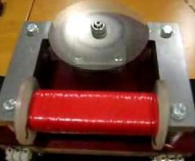
Peter, thanks for the suggestions. The reedwitches did work after I froze them and heated up several times, but I still could not get the perfect timing. I could either get two pulses perfect, one a tinny bit off and the third pulse wont fire, or one pulse perfect with other three pulses way off. I tried to center the timing wheel but with no luck, if I move a reedswitch near enough the magnets I can get all the pulses, but they are not eaqual in pulse width. When I move the reedswitch just a half of milimeter away, I can get only three pulses. Yesterday I spent all day adjusting and readjusting the timing, I tried three different timing wheels – no luck. The problem is in my method of attaching the timing wheel to the shaft:
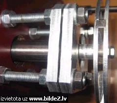
As you can see it is only bolted to a thred in the shaft end through three 6mm thick aluminum spacers. No bolt is gonna be precise enough. It’s a shame I did not think more about the timing when making the shaft, I would made it better I know the reedswitch would work well for this purpouse, but due to my bad job on the shaft, I have to consider different switching methods. I really want to get the motor working and I have already spent too much time with reedswitches and no luck. The first try was good, but also there the timing wasn’t exactly very accurate.
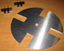
So I went to local electronic shop today to buy some more 2N3055 transistors and also bought some optointerrupters, they had only two pieces of ITR8102. They were very cheap, so I bought both of them.
Here is the data sheet: ITR8102 : http://pdf1.alldatasheet.com/datasheet-pdf/view/105611/ETC/ITR8102.html
The gap fo the optointerrupter is 3mm wide, so I made a timing wheel out of 2mm thick aluminum. The wheel is designed so that there will be 4 pulses at 90 degree angles, each one 15 degree in duration (exactly half of the rotor leg width). If this wont work well, I can make new timing wheels easy in the matter of minutes. Also the gap of the optotrigger is deep enough to allow that little offcenter I have.
I figured the circuit should be something like this:
Of course I am not sure if this optotrigger will handle more than one transistor this way. Maybe I need this second stage amplifier. In that case I have some small 2N3584 transistors, just like in the John Bedini’s cap pulser setup, where these transisitors are used to trigger the SCR.
Maybe I can use that? Here’s a data sheet: 2N3584 : http://pdf1.alldatasheet.com/datasheet-pdf/view/76198/MICROSEMI/2N3584.html
I think It shouldnt be a problem for me to solder it all together, I have some experience on that (have built some cap pulser setups). I just need to verify that the circuit I drew is correct and if someone has any comments about this. I intend to power the motor from 24V with two batteries in series. Thank you all, Jetijs
# 334 ; by lighty, Member, 11-14-2007, 07:12 AM
@Jetijs, It would be better to use opto-reflective switch since then you will only need to have one disk with reflective surface and you could simply change your timing with a bit of a non-reflective paint. No need for any slot or additional machining. On the other side the electronics would be more complex because of the need to control the levels of the photo-transistor in cases of the changing reflexivity. So, in my opinion you should stick with photo-interrupter switch for the moment.
Also, it would be easier to drive MOSFET- they are basically driven by voltage rather than by current so they’re simpler to work with in logic circuits or in this case in switching circuit. IRFP450/460 comes to mind since they’re rather common and not expensive. Also, when driving MOSFETs with voltage it would be harder to burn out your opto-interrupter switch (not impossible though).
I usually use much more complex circuit topology since for various reasons I need to have my signal conditioned, cleaned, pulse response advanced and to ensure extremely fast switching with advanced control I use MOSFET driver ICs. You don’t need all that so the schematic I suggest is the following.
Please note that the first schematic has an inverted logic – that means that when the photo transistor is active (when the slot allows for the passing of light) the MOSFET will act as an open switch.
If you want MOSFET to conduct current when the slot is passing the light then simply use the second schematic called “non-inverted” (it has one bipolar switch added in order to invert the signal logic and also to ensure better control over MOSFET- in my experience for this simple application a small transistor like 2N2222 or BC635 or something like that that you can get your hands on).
As for the values of the resistors it can easily be calculated when you specify the exact voltage you’ll be using. Also, if the inductive collapse voltage should exceed semiconductor switch maximum rating you can easily add some fast transil diode in parallel in order to protect the device- the drawback is that if the protection diode conducts the most of the recovered energy will be grounded (but at least it will protect your semiconductor until you come up with some solution for the problem). For example the good old 2N3055 is rated about 70V CE voltage and anything higher than 80-90V would probably kill it. 2N3584 would be much better choice because IIRC it has about 250-300V CE voltage rating but I’m not sure about it’s current capability (did you measure the power consumption of the coil) since I didn’t look at the datasheet yet.
Anyway- I suggest you use MOSFET since it’s much easier to work with (although not without it’s quirks when working in more severe electrical conditions) but Peter might suggest otherwise. I guess you should listen to his advice- he’s the chief of this parade anyway.
All you need to do is to replace MOSFET with BJT power transistor and add another resistor between base and emitter to ensure proper shut-down.
P.P.S.: Since you’ve asked about whether your circuit would work the answer is most likely but it depends a lot on the power ratings of the opto-interrupter transistor. I will look at it more closely tomorrow, it’s almost 4AM and my brain is shutting down.
# 335 ; by Peter Lindemann, Senior Member, 11-15-2007, 01:32 AM ; Next Step
Jetijs, Apparently, you would like to abandon the magnetic reeds and move on to the opto-interrupters. Without a thorough study of what happened, you will never know. I believe the problem is with your magnets, the aluminum wheel they are mounted in, and the steel bolts nearby causing field distortions. In my estimation, you have not actual learned WHY the magnetic reeds are misbehaving at this stage of testing.
OK. On to the optical approach. As I said in an earlier post, the difficulty with this method is in the intermediate stage. The Data Sheet on the ITR8102 states that the photo-transistor output stage can only handle 50ma of current and a maximum C-to-E voltage of 30volts. This current level is insufficient to drive three output transistors directly.
As you can see, a number of different suggestions have already been made. Any of them can be made to work to one degree or another. Each solution will have its own issues. My suggestion is that you stay with the Bi-polar Transistors for now and go with one stage of signal amplification in between the photo-transistor and the power transistor.
The system I use is quite simple. Replace the magnetic reed switch with a medium power PNP transistor. So, the first stage of control will remain similar to what you had with the reed switch. The emitter of the PNP is connected to the Positive Supply and the collector is connected to the first resistor in the voltage divider. The base of the output transistor is still triggered between the two resistors of the voltage divider.
Next, we are going to create a second voltage divider operated from the NPN photo-transistor. So, the emitter of the NPN photo-transistor is connected to the circuit ground (negative of the supply) and the collector is connected to the first resistor of this new voltage divider. The second resistor connects to the Positive Supply and the mid-point between the resistors connects to the base of the PNP. So now you have positive control of your POWER NPN through one inverted stage of signal amplification. The resistors in the voltage divider operated by the photo-transistor can be 2k ohms each, or higher and still be sufficient to turn the PNP on quickly and completely. Just keep the total current in this section below half of the rated current maximum of the photo-transistor, or about 25ma.
Set this system up for one power transistor and one coil. I suggested in an earlier post that you run some tests with the values of your primary voltage divider to see how much higher the resistor values can be raised above your currently used 200 ohms and still get clean switching of your power transistor. See if the transistors switch cleanly with 680 ohm resistors. If they do, then just make two more voltage dividers to run two more power transistors to run the other two coils. Parallel the voltage dividers and run them all from the collector of the PNP.
Make sure you have an output diode on each of the coils when you test the system. Good luck, Peter
# 336 ; by Jetijs, Member, 11-15-2007, 03:02 AM
Ok, tkank’s Peter. For what I understood from your post, the circuit should now look something like this:
Is that correct? Thank you
Edit: Can I use the MJ2501 PNP transistor for triggering? It is a high power transistor, but I found some of them laying around. The max base current of this transistor is 0.2A, but that is the absolute maximum rating.
Here is the data sheet: MJ2501: http://pdf1.alldatasheet.com/datasheet-pdf/view/12394/ONSEMI/MJ2501.html
If I can use this, then I need no aditional parts and can start soldering. Jetijs
# 337 ; by lighty, Member, 11-15-2007, 07:31 AM
Quote: Originally Posted by Peter Lindemann # 335 : My suggestion is that you stay with the Bi-polar Transistors for now and go with one stage of signal amplification in between the photo-transistor and the power transistor.
End of quote.
Why bipolar transistors? I am not asking this because I doubt your judgment but because I really want to know. Is there any difference at this stage? I mean from first hand knowledge I know there is a significant difference when dealing with dielectricity but at this stage it’s simply a switch. Or not? I never experienced any adverse effects when I compared MOSFET and BJT as switch (although the MOSFET proved to be faster and had lower turn-on resistance). Is there any difference?
# 338 ; by Peter Lindemann, Senior Member, 11-15-2007, 08:40 AM
Jetijs, Yes, that is the idea. Try the PNP you have on hand. Also, see if the 200 ohm resistors can be a higher value, like 680 ohms, and still turn your power NPN on all the way. Run the test with one coil and see how it works. Then try to power all three coils. Peter
# 339 ; by Peter Lindemann, Senior Member, 11-15-2007, 08:48 AM ; MOSFET vs Bi-Polar Transistor
Lighty, As you know, MOSFETs can work with these circuits. The biggest problem with FETs is the capacitive nature of the gate. Getting the device to turn ON quickly is no problem, but getting them to turn OFF quickly is a little harder. The little FET driver ICs help, but that is one more level of complication. I am trying to demonstrate circuits that are simple to understand, as well as work effectively.
Again, for you, I’m sure you can make MOSFET circuits do all of these things, but I am trying to keep it simple for learning purposes. Peter
# ; by Peter Lindemann, Senior Member,
# ; by Aaron, Energetic Scientist,
# ; by nali2001, Member,
# ; by Jetijs, Member,
# ; by lighty, Member,
# ; by adam ant, Senior Member,