# ENERGIZERS by John Bedini, PART 2/2:
# THE TESLA SWITCH http://www.icehouse.net/john34/tesla.html
We used as a starting point for our experiments, the switching device John Bedini had built for the Tesla Symposium. Our goal was to upgrade this switching device for ordinary car or motorcycle batteries. Because we had already learned that the efficiency will go up the more we load the circuit, we decided to load this Tesla circuit also.
We found that when we connected a second lamp, the first lamp instantaneously became brighter. Each time we disconnected and connected one of the light bulbs or other loads in the circuit, we saw a spark about a half inch long. The light of this spark was noticeably different from the light of sparks observed when experimenting with high voltages. We discovered that in addition to X-rays we were also generating scalar waves. These were detecting using a scalar wave detector built by John Bedini, which was based on a plan furnished by Tom Bearden.
THE CIGAR-BOX SIZE TESLA SWITCH:
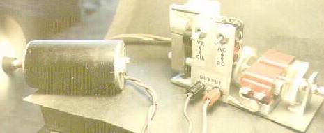
Bedini was then invited to speak at the Tesla Centennial Symposium in Colorado Springs, CO, on August, 11, 1984, The symposium honored the 100th anniversary of the arrival of Nikola Tesla in the USA, and was sponsored by the Tesla Committee, by the Institute for Electronic and Electrical Engineers (IEEE), Pikes Peak Section, and by the Ford Aerospace& Communications Corporation,Colorado Springs Operation. At the symposium, Bedini demonstrated an inexpensive, cigar-box sized Tesla-type converter witch he had recently built. Throughout the demonstration, which lasted a full 24 hours during the symposium, a constant load was being drawn out of the system to do work, Nevertheless, the converter kept the nickel-cadmium batteries fully charged! The concept, witch had been originated by Nikola Tesla, was given to John Bedini by Ronald Brandt, who was a personal friend of Nikola Tesla. Brandt is reputed to have a similar converter which he has used for years without loosing the battery charge. Bedini presented the schematic diagram showing how to build the solid-state device, and then released copies of the schematic diagram.
The scalar wave battery charger.:
It happened on a Saturday night on the Bill Jenkins Show. I was invited to speak between the Dodger Baseball game and the news. The show had about one hour remaining to the end at 12:00 midnight. Bill Jenkins knew nothing about what I was going to talk about that night. The time came for us to go on the air and the program started. I then proceeded to talk to the audience and I said, “Did anyone ever try this experiment: Did you ever try charging two capacitors, say about 22,000 microfarads, with 12 volts and then putting the two capacitors in series and dumping the charge across that same battery?” In the next few minutes the phone lines started to light up so I took the first phone call and answered the person’s question. By the time the next call came up, it was time for news. By the time the news was over, I was on my way home with Bill.
Well two weeks went by and it came time for the next radio show. This is where Ray and Bill showed up. Bill Jenkins called for the radio station Chief Engineer, and said to Ray and Bill: “Well Show Us what You Got.” Bill said, “WE HAVE A SCALAR WAVE BATTERY CHARGER.” The Engineer said, “Sure you do.” Bill said, “We do. We built this to John Bedini’s plan.” The Engineer said “OK, LET’S TEST IT.” About this time Bill threw the switch on the side of the box , the lights and the motor started to run and Bill said to the station Engineer, “GO AHEAD MEASURE THE BATTERY.” The station Engineer put the best meter the station owned across the battery. The Engineer looked over to Bill Jenkins and Me and said, “I do not believe this. This battery for all practical purposes is dead but yet it’s running the lights and the motor and the battery is not running down.”
For weeks after that the station was flooded with calls from people trying to find out where they could find this Bill and Ray. About one month after that I got a phone call from Bill. He said “Would you like to come over to my house. I said, “Sure.” I got to his house and we talked for about two hours. At the end of our talk I asked Bill if I could have a copy of the circuit diagram. He said, “Sure. After all, you invented the thing.” This is where the bad part comes in. What the hell happened to Bill and Ray with this box? They never did anything with it. Here is the good part, the circuit diagram as he drew it I have only copied it in my paint program. IT’S YOURS, HAVE FUN. I NEVER BUILT IT. I ONLY HAD AN IDEA ABOUT A PORTABLE BATTERY CHARGER YOU NEVER HAD TO PLUG INTO THE WALL FOR POWER.
Some things in the circuit look wrong to me. But this is the circuit just the way I received it. So that’s what I’m putting on the page. I have not studied this circuit and I haven’t built it. I’m just giving you the information.
WARNING: BATTERY COULD EXPLODE IF YOU HAVE FAULTY CONNECTIONS. BUILD AT YOUR OWN RISK.
Good Luck. John Bedini
I might say something here, Ron Cole and I worked together, some of the circuits He did others I did. We are still very good friends to this day, except that I moved to Idaho and Ron stayed in California, but we still talk on the phone to each other.
# Some of the pictures you can find at : ENERGY MACHINE PICTURES http://www.icehouse.net/john34/pictures.html
This is a picture of a small model G-Field that Ron Cole made to test the efficiency.
The test were performed by Ron Cole On two G-Field Generators. Input Power, Output Power, and Load Res In Ohms
– Test 1 Input Power 25.4 Volts at 3.90 Amps= 99.00 Watts , Output Power 48 volts No Load
– Test 2 Input Power 25.3 Volts at 3.90 Amps= 98.67 Watts , Output Power 28 Volts .75 Amps= 21 Watts at 37.33 Ohms
– Test 3 Input Power 20 Volts at 3.39 Amps= 67.80 Watts , Output Power 50 Volts at 3.70 Amps= 185.19 Watts at 13.50 Ohms
– Test 4 Input Power 21.9 Volts at 2.30 Amps= 50.37 Watts , Output Power 20 Volts at 31.75 Amps= 634.92 Watts at .63 Ohms
The above test results were obtained from a small kromrey generator, built by John Bedini in 1983. The test was conducted by Tom Bearden, and John Bedini in late 1983: Later they were reconfirmed by Dr. Patrick Flanagan.
The test were conducted in a manor as to prove the converters most basic concept; (Input Power) versus (Output Power) into a usable load. The connection to replace used energy to the battery as a self charging action was not in place, so as to prevent any confusing reflex factors.
All of the above reconfirmed by, Ron Cole, on the evening of 11-9-1984. We also obtained results that far exceeded the results shown above, when the battery self charging circuit was connected.
Ron Cole 11-13-84 .
Sub Note: Small 1/2 AH, NiCad Batteries were used for input Source.
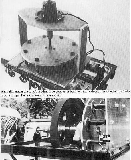
James Watson, one of the more advanced of current experimenters, has built several demonstration machines, each with increasing performance. Each overcomes its own internal friction and recharges its own batteries. As of this writing, he is working on a solid state device. This writer will closely follow his progress and provide all possible encouragement.
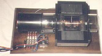
This is a picture of a small G-Field Generator built by Bedini Electronics 1984.
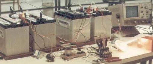
This is a picture of the Tesla Switch built by Eike Mueller the load is a 350 watt quartz light
# See also page 13 to 18 of Captain Kelly’s ‘D3’ pdf file, about Tesla, Cole, Bedini SWITCHES http://panacea-bocaf.org/files/patrickkelly/D3.pdf