Lindemann, Peter, Attraction Motor part 1: (page created for November 2007 update)
Dr. PETER A. LINDEMANN
from http://www.free-energy.ws/lindemann.html
Peter A. Lindemann became interested in Free Energy in 1973, when he was introduced to the work of Edwin Gray. By 1981, he had developed his own Free Energy systems based on variable reluctance generators and pulsed motor designs. During the 1980’s, he worked off and on with both Bruce DePalma and Eric Dollard. In 1988, he joined the Board of Directors at Borderland Sciences Research Foundation, and served until 1999. Currently, he is a Research Associate of Dr. Robert Adams in New Zealand, as well as a close collaborator with Trevor James Constable in the United States. Dr. Lindemann is one of the foremost authorities on the practical applications of Ether technology and Cold Electricity. He is currently Director of Research for Clear Tech, Inc.
ARTICLES :
1. Thermodynamics & Free Energy, Borderlands Magazine, 3rd Quarter, 1994 (Click to view actual article, page 1 http://www.free-energy.ws/images/PLthermo1.jpg , http://www.free-energy.ws/images/PLthermo2.jpg , http://www.free-energy.ws/images/PLthermo3.jpg , http://www.free-energy.ws/images/PLthermo4.jpg , http://www.free-energy.ws/images/PLthermo5.jpg or download in PDF Format http://www.free-energy.ws/pdf/Thermodynamics.pdf )
2. Tesla’s “Self-Acting” Engine, Borderlands Magazine, 3rd Quarter, 1995 (Click to view actual article, page 1 http://www.free-energy.ws/images/PLtesla1.jpg , http://www.free-energy.ws/images/PLtesla2.jpg , http://www.free-energy.ws/images/PLtesla3.jpg , http://www.free-energy.ws/images/PLtesla4.jpg or download in PDF Format http://www.free-energy.ws/pdf/Self-Acting%20Engine.pdf )
3. The World of Free Energy, March 1, 2001 (Click to view article http://www.free-energy.ws/lindemann-1.html )
Electric Motor Secrets
by Peter A. Lindemann, D.Sc. from http://www.free-energy.ws/products.html
NEW DVD. Laying dormant within the modern electric motor is a deep, dark secret. For the last 176 years, that secret has held the electric motor to its present level of performance. But in 1975, a quantum leap in electric motor design was made by an American inventor named Bob Teal. Teal’s Magnipulsion Engine produced COPs between 8 and 10. Using lab demonstrations, patents, diagrams, and private documents, Dr. Lindemann takes you on a trip through the history of electric motors, resurrecting the secret of Magnipulsion, and revealing the future of electric motor design. (2 hrs 30 minutes) DVD – (Universal format) – $29.95
Tesla’s Radiant Energy
by Peter A. Lindemann, D.Sc.
After 105 years of mystery, the truth about Tesla’s Radiant Energy system is revealed. This is the lecture Dr. Lindemann presented at the ExtraOrdinary Technology Conference on July 30, 2006 in Salt Lake City, Utah. Talking through a fully illustrated PowerPoint Presentation with 85 slides, Dr. Lindemann explains exactly what Radiant Energy is. Citing dozens of quotes from Tesla’s patents and lectures, Dr. Lindemann presents the complete development of Radiant Energy in Tesla’s own words. This lecture is the definitive communication on Tesla’s model of electricity and its relationship to the production and use of Radiant Energy. (1 hr 30 minutes) DVD – (Universal format) – $29.95Top of Form 1 Bottom of Form 1
The Free Energy Secrets of Cold Electricity
by Peter A. Lindemann, D.Sc., 2000
In the 1970’s, inventor Edwin Gray developed an electric automobile engine that produced 80 horsepower and recharged its own batteries. It ran on what he called “cold electricity.” This amazing technology remained shrouded in mystery until September 2000, when Dr. Lindemann delivered the lecture in the video sold below. This book was published 5 months later, and covers the same information as the video by this title. It explains how Edwin Gray produced “cold electricity” and how that relates to Nikola Tesla’s discovery of “Radiant Energy” over a century ago. All of the images that appear as slides in the video are reproduced in the book, as well as complete reprints of Edwin Gray’s three US patents, and three of Nikola Tesla’s US Patents, which relate to the subject. This is an important study manual for serious researchers. Ed Gray’s EMA motor produced 40 times more power than he took from his batteries. The secret is in the power supply and this book tells how it works!
Book – 2nd Edition Printing (there is no 3rd Edition of the book). Book – $29.95
(3 hrs). DVD – (Universal format) – $29.95
The World of Free Energy
by Peter A. Lindemann, D.Sc.
Dr. Lindemann does it again! In his landmark presentation at the KeelyNet Conference in June 2001, Dr. Lindemann gives an up-date on the Ed Gray EMA motor power supply, as well as show: John Bedini’s motor designs that recharge their own batteries, Bill Muller’s low drag generators, Dr. Robert Adams’ magnetic heaters, Tom Bearden’s MEG and other magnet powered transformers, the amazing “ChemAlloy” that spontaneously dissociates water, Stan Meyer’s water fuel-cell designs and their spin-off at Xogen, and much, much more. This video has more information on more Free Energy systems than has ever been released to the public before. A must for serious Free Energy researchers worldwide! (2 hrs.). DVD – (Universal format) – $29.95
The History of The E.V. Gray Motor
by Norman Wootan
The truth is finally revealed. The mystery about Ed Gray’s EMA motors is finally over. With two recovered EMA motor prototypes on stage at the KeelyNet Conference in June 2001, Norman Wootan discusses every design feature possible. Every single way the real motors deviate from the designs revealed in Gray’s Patent are discussed in detail. Now you can see with your own eyes how it was really done. This video is a must for serious researchers wanting to convert Radiant Energy into mechanical power. A great companion piece to “The Free Energy Secrets of Cold Electricity” by Dr. Lindemann (book or video) where the EMA power supply is discussed. (2 hrs.). DVD – (Universal format) – $29.95
Lindemann Rotary Attraction Motor
from http://www.esmhome.org/library/bob-teal/index.html
Video: Lindemann Rotary Attraction Motor http://www.esmhome.org/library/bob-teal/lindemann-rotary-attraction-motor.wmv 6.21mb video in WMV format 8 minutes long
This proves this new type of motor can be built by modifying off-the-shelf motors. This demonstrates all of the basic principles in the Electric Motor Secrets DVD.
No efficiency or power claims are made. This is simply an early test to demonstrate the principles. Closing the gap will increase the power.
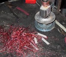
Windings removed from rotor and rotor is shaped to be more like a rectangular bar.
 Closeup of modified Series 1 motor.
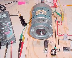
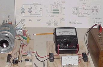 Whole setup of Lindemann Rotary Attraction Motor
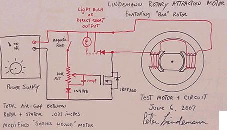
Lindemann Rotary Attraction Motor schematic of modified Series 1 motor.
Rotary Attraction Motor Update
By Peter Lindemann, D.Sc. April 25, 2007 from http://www.free-energy.ws/electric-motor-secrets/attraction-motor.html
In the DVD presentation “Electric Motor Secrets”, a no Back EMF, Magnetic Attraction Motor, with high torque and high electrical recovery is discussed. Near the end of the presentation, a rotor design called the “S” rotor is shown. In lab tests conducted after the film was finished, it was determined that the “S” rotor is more difficult to fabricate and does not perform better than a simpler design. This design consists of a simple cast iron rotor in the form of two cross bars. I call it the “X” rotor, and the configuration is shown below.
The basic motor configuration is as follows. The stator pole faces describe 30 degrees of arc. Each rotor cross bar face also describes 30 degrees of arc. There are four power strokes per revolution of the shaft. A power stroke begins when one of the cross bars is in the position shown in the illustration.
The commutator turns the power coil ON for 15 degrees of rotation, and then turns the power OFF. The power then remains OFF for 75 degrees of rotation. This cycle repeats every 90 degrees of rotation.
So, the power ON phase draws the cross bar 1/2 of the way into alignment with the stator pole faces. The power coil then turns OFF and discharges its magnetic field during the second half of the way into alignment. By the time full alignment is made, the magnetic field is gone and the iron bar section of the rotor rotates out of alignment with no resistance.
Electric Motor Secrets Discussion Forum http://www.energeticforum.com/renewable-energy/271-electric-motor-secrets.html
Lindemann Rotary Attraction Motor
From PESWiki http://peswiki.com/index.php/OS:Lindemann_Rotary_Attraction_Motor
Peter Lindemann has been coaching a forum http://www.energeticforum.com/renewable-energy/271-electric-motor-secrets.html in replicating a modified off-the-shelf motor, adding a Bedini-like circuit for improved efficiency, smoother running, and possible over-unity performance.
Status : “I have been trying to encourage people to understand the basic principles, and have not focused on a specific design. So at this point, there is no schematic, no instructions, no published parts list and no reports of successful replications yet. I am working with a number of people who have various degrees of skill, time and resources, who are in the process of building models. Every design is different, according to the interests of the builder. Each person is bringing their own original ideas to their project and I am encouraging this.” — Peter Lindemann (Sept. 25, 2007)
On Oct. 1, 2007, from noon to 1:00 pm Mountain time, as part of the Free Energy Now http://freeenergynow.net radio series, Sterling D. Allan will conduct a 1-hour interview with Peter Lindemann regarding his Rotary Attraction Motor and related technologies.
“I was able to see Peter Lindemann demonstrate his motor and circuit technology at a booth he had at the ExtraOrdinary Technology conference in Salt Lake City in July, 2007. The Lindemann Rotary Attraction Motor video below shows the set-up that Peter was demonstrating at the conference. It was an impressive set-up; a convincing presentation. He told me that discloses how to do all of what he does, and he is glad to see others replicate it, but he doesn’t put it all together in one place. He all but said that if one were to piece everything together, one could build a self-sustaining over-unity system with energy left over for practical use.” — Sterling D. Allan (Sept. 25, 2007)
# 8 min video: Lindemann Rotary Attraction Motor – Video was recorded June 13, 2007 (YouTube http://www.youtube.com/watch?v=wMzSzChCkrM; June 17, 2007)
“Designed by Peter Lindemann. This proves this new type of motor can be built by modifying off-the-shelf motors. This demonstrates all of the basic principles in the Electric Motor Secrets DVD, which discusses the Bob Teal attraction motor technology. No efficiency or power claims are made for this Lindemann Rotary Attraction Motor. This is simply an early test to demonstrate the principles. Closing the gap will increase the power. Schematics and pics of inside of motor are here: “
# Memo from Lindemann: On Sept. 25, 2007, Peter Lindemann wrote:Pictures of the modifications made to the Series Motor [as depicted in the image to the right here taken from the above video] are found on the bottom of this page: http://www.esmhome.org/library/bob-teal/index.html This page also shows a schematic that was used on the motor at the time, but I am currently running the motor using the circuit from the first link (above).”
# Notes on Video contents : Early test of series 1 DC motor modified to run on attraction principles discussed in Electric Motor Secrets DVD
– All the windings are removed from the motor.
– The rotor is shaved to be more rectangular — more like a cross bar.
– The commutator is abandoned; there are no brushes.
It basically free-wheels. The only friction is bearing friction.
The circuit is simple, using a mosfet switch, triggered by a magnetic Reed switch, which is activated by magnets on the pulley.
It will run in either direction. The movement of the rotor is independent from the input (e.g. loading the rotor does not increase the amperage going to the motor) — a true “no back EMF motor”.
In short-out mode (resembling a back EMF motor), rather than recovering energy in a light bulb, the motor runs more roughly, draws more than twice as much current, and runs slower.
Lindemann-modified motor is compared to a factory, unmodified motor, which doesn’t free-wheel. Close-up given at the end to show the motor manufacturer label and specs: April 1983, Howard Industries….
# History : On March 14, 2007, Aaron wrote http://www.energeticforum.com/renewable-energy/271-electric-motor-secrets.html:
Thank you all for responding to my announcement that the Missing Bob Teal Interview had been found. The link to view this interview is here: Energetic Science Ministries | Bob Teal | Magnipulsion http://www.esmhome.org/library/bob-teal/index.html
But first, I’d like to give you a little bit of history on how this came about. As of 2007, the work of Bob Teal and his Magnipulsion Engine from 1976 has all but been forgotten. Teal was granted two patents for his mechanical, reciprocating electromagnetic attraction engine in 1977 and 1978. However, nothing in these patents disclosed the essential secrets of its extraordinary operating characteristics. Its capabilities were only hinted at in a rare piece of company literature. By 1978, Teal was out of money, and work on the Magnipulsion Engine had stopped.
Luckily, these documents fell into the hands of Free Energy researcher Dr. Peter Lindemann in 1979. By 1983, a group of people in Santa Barbara, California, including Peter Lindemann and Michael Knox, were working on reviving Teal’s ideas and developing their own advanced power plant called the Flux Motor. The Flux Motor produced extremely high torque and was able to recover over 80% of its input electricity. Unfortunately, this group also ran out of money before finishing their work. So, the secrets of these amazing electric motors lay quietly in a file box for 24 years.
In January of this year, Dr. Lindemann decided to produce a new DVD called Electric Motor Secrets http://peswiki.com/index.php/Review:Electric_Motor_Secrets_DVD_by_Peter_Lindemann , and base this new educational film on reviving Bob Teal’ s Magnipulsion Engine principles and designs. I was working with Dr. Lindemann on another project when I learned of his plans. Remarkably, eight years ago, I was given a VHS tape by Free Energy researcher Dr. Lawrence Kennedy. It included an interview of a man demonstrating an extraordinary engine back in the 1970’s. That man was Bob Teal, and he was demonstrating one of the last models of the Magnipulsion Engine ever built! In this film, he shows a number of the extraordinary characteristics of this machine. First, it ran on very low current by eliminating the counter EMF. And second, it recovered over 90% of its input electricity to either recharge its batteries or run light bulbs. The short film is a remarkable piece of history.
I have already viewed Dr. Lindemann’s Electric Motor Secrets and I guarantee to you that he shows everything about how the Magnipulsion Engine worked and much, much more. So, here is the link to the Missing Bob Teal Interview and the links to learn how to build the electric motor of the future.
Peter Lindemann posts on Energetic Forum about the Attraction Motor Concept
From http://www.energeticforum.com/renewable-energy/271-electric-motor-secrets.html
(MDG nov07: Reading this posts will clarify all the important details to take care of, to successfuly make a ‘free electricity generator’. My opinion is that it is the first very clear and quite simple reproductable Free Eenergy Generator given freely, generously to humankind, and that can give enough power to supply the need of a family, a workshop or a small factory … For me that’s THE ACTUAL BEST SOLUTION to give power to the still undevelopped countries. Thousands thanks to Dr. Peter Lindemann, that may gain a place in God’s paradise, in the next life, because of his faith and good hearth, Amen.
Just reconfigurating an existing electric motor in an highly efficient attraction mode, then connecting it mechanicaly to an alternator, and also recycling most of the used electricity through a Bedini/Gray/Teal capacitor/battery circuit, will permit the system to self-sustain and offer extra electricity for external use. Let’s go for replication, improvement, mass production and USE! Victory is now at our feet, let’s take it higher, if God’s will.)
Page 1:
# 2 ; by Aaron, Energetic Scientist, 04-15-2007, 08:25 AM : Electric Motor Secrets Official Discussion Forum
The purpose of this thread is for the discussion of the DVD by Dr. Peter Lindemann called Electric Motor Secrets.
It would be greatly appreciated if you buy your own copy and watch it before posting any messages here as it will answer almost anything you want to know about Bob Teal’s Magnipulsion engine.
However, Dr. Lindemann will be contributing some very helpful information here for those of you who are interested in building any of the versions of the the motor(s) discussed in the DVD.
Please keep your posts in this group on topic: Bob Teal, Magnipulsion, Magneteal, Electric Motor Secrets, etc…
If you want to discuss other attraction motor concepts or similar topics but not directly related to Electric Motor Secrets, please feel free to start a new thread.
# 3 ; by Peter Lindemann, Senior Member, 04-15-2007, 11:37 PM : Welcome and Thank you
Hello Everybody, Thank you, Aaron, for setting up this forum. This will be the only forum I will participate in for the discussion of the information in my new DVD Electric Motor Secrets.
Here, we can discuss:
1) What Back EMF is,
2) How to engineer around it,
3) How to maximize mechanical energy production in attraction motor designs,
4) Bob Teal’s Magnipulsion Engine,
5) and problems encountered in building models.
Certain other topics may be allowed on a special basis, or used to start a new thread.
In order to be fair to others in the Forum, please do not post here if you have not seen the DVD presentation Electric Motor Secrets. I look forward to helping all of you fully understand these ideas.
# 5 ; by Peter Lindemann, Senior Member, 04-16-2007, 04:15 AM : Designing a motor
Eric, The magnetic attraction motor, whether it is Teal’s electric solenoid engine, my “S” rotor, or other designs, can produce mechanical energy at a different rate of conversion than a standard induction motor, due to the lack of Back EMF. Exactly what this new conversion rate is is still not known, and must be determined by experiment.
You can see from my DVD, the Back EMF is responsible for neutralizing between 50% and 90% of the applied energy in a standard induction motor, depending on load conditions. Assuming a moderate load, it seems reasonable, then, to conclude that it may be possible to create a 1 hp motor that only draws 200 watts. If the electrical recovery system can return 85% of this, then the machine will run on 200 watts, produce 1 hp of mechanical energy, and return 170 watts to the batteries.
This suggests that 1 hp of mechanical energy may be able to be produced for 30 watts. This is how Teal accomplished what he claimed. At this point all of these things must be re-worked out by experiment.
# 7 ; by Peter Lindemann, Senior Member, 04-16-2007, 11:36 PM : Book on Solenoid Design
Eric, You aren’t rambling. You are totally on the right track. A good book that covers the math on what you want is: “Solenoids, Electromagnets, and Electromagnetic Windings” by Charles N. Underhill. ISBN #1-55918-096-X. This book was first printed in 1914. I like the old books because they are factual, and uninfluenced by changes in theory and politics. It is currently available from Lindsay Publications as a reprint.
This book will let you calculate magnetic field strength for wire size, number of turns and current. Teal’s big secret was the method whereby he minimized the air-gap in the solenoid at the middle of the stroke. This sort of solenoid design is not discussed in the book, so you will not be able to accurately calculate the mechanical energy produced. You will have to build a model of the machine and MEASURE the mechanical energy generated to fully understand what it does.
# 9 ; by Aaron, Energetic Scientist, 04-17-2007, 05:40 AM ; There are a handful of used copies there:
Solenoids, Electromagnets, and Electromagnetic Windings by Charles N. Underhill : http://www.amazon.com/gp/product/155918096X/102-0964424-6340167?ie=UTF8&tag=energscienmin-20&linkCode=xm2&camp=1789&creativeASIN=155918096X
# 10 ; by Peter Lindemann, Senior Member, 04-17-2007, 06:24 AM ;
Dear Gyula, No problem. These types of groups are full of stuff that is pure speculation, so your skepticism is warranted. My DVD covers a lot of ground. First, I show how to build a Dynamometer, and then run a Dyno test on an induction motor. Then, I show exactly what Back EMF in the motor is, and why it is the main factor holding back the performance of the motor. Then I show the history of motor designs that have No Back EMF, and what the problems have been in allowing these motors to produce high torque. That brings us to Teal’s Magnipulsion Engine and how he solved these problems. I also show an advanced motor I built in 1983 that solved most of these problems, as well. I end with some speculative designs that have not been fully tested yet, but are in the process of being tested now.
So, there is a lot to learn. The purpose of the DVD is to get people to think about Zero Back EMF designs as the way to produce motors with COP > 1.
With all of this in mind, you may want to wait for some more definitive testing data to come in. On the other hand, some people like to be shown basic principles so they can come up with their own design that works. There are dozens of “solutions” that will allow a working model to operate in the high torque “window” while returning most of the electrical input.
As for Bob Teal, I do not know if he is still alive. If he is, he is 85 years old and probably living in North or South Carolina. I have not tried to contact him.
# 12 ; by Peter Lindemann, Senior Member, 04-17-2007, 02:17 PM ;
Eric, Yes, you are missing something. The idea of efficiency is based on the First Law of Thermodynamics, often referred to as the Law of the Conservation of Energy. This idea is that energy can be converted from one form to another, but it is neither created nor destroyed by its passage through the mechanism. I do not believe in the idea of “Over Unity” because this Law is either correct and in-force at all times, or it is not. So, it is logical that the Law cannot be both correct and in-force, AND violated at the same time. It is well established that the energy conversion rate for the direct induction machine is 746 watts = 1 horse power = 550 foot-pounds per second of mechanical energy.
The magnetic attraction motors that my DVD discusses can be called indirect induction machines, as they use direct induction for the creation of a magnetic field, but it is the magnetic field that causes the mechanical energy production. So, the electricity input is only indirectly related to the production of mechanical energy in the machine. I have postulated that this process, which is NOT the same process as Faraday’s induction, operates at a different conversion rate, somewhere around 200 watts = 1 horse power = 550 foot-pounds per second of mechanical energy.
Then, by configuring the machine to operate on short pulses of DC current, an inductor can be charged with electric current. This in turn, causes the creation of a magnetic field. As this magnetic field grows, it can be used to attract a piece of iron, producing mechanical energy. When the field is maximized, the current can be shut off, and the magnetic field will collapse. The collapse of the magnetic field will induce a new current of electricity that can be recaptured by the circuitry, and re-applied to the battery system, thus recovering up to 90% of the input electrical energy. If the machine can produce more than 10% mechanical energy production, then there is an anomaly here which needs a creative explanation.
So, the issue here is, how much mechanical energy can be produced by this process? The answer is, quite a lot, if you design the machine correctly. Way over 10%, in fact. So, when all of these processes are designed right, the machine apparently produces significant amounts of energy that are not explained by the Laws of Conservation.
So, three possibilities exist to explain this. The first is, that the Law of Conservation is just plain wrong, and nothing is being converted into anything else in any of these machines. Most people are not willing to entertain this idea. The second is, that the conversion rate for the indirect induction machine is different than for the direct induction machine, and therefore it can produce more mechanical energy from less electricity because that’s what it does. Again, most people find this idea difficult to accept. The third is, that the machine is somehow tapping an unseen source of energy and converting it to the seen energy surplus. Many scientists are starting to consider this idea as the explanation for these phenomena.
No matter which explanation you pick, OVER UNITY is NOT one of the possibilities.
# 15 ; by Peter Lindemann, Senior Member, 04-19-2007, 04:24 AM ; Modifying a Shaded Pole Motor
Eric, I took a look at your pictures. (Eric’s page, Home http://home.comcast.net/~ecousins25/wsb/html/view.cgi-home.html-.html )
You are totally on the right track here!!!! Cutting the stator core laminations is a bit tricky because they are covered with Silicon (glass) insulation. It tends to dull your cutting tools pretty fast.
Also, you’ll find that running the coil on 12 volts DC will give you a lot of power, since there is no Back EMF in the coil to buck the input. You won’t be able to run it on 120 volts DC as you suggested. It will melt the coil.
Make a new rotor that is just a bar (with curved ends) of cast iron across the section of the stator that is left after you cut away the sections you have marked.
Set the commutator to turn the coil ON when the front edge of the rotor is at the front edge of the stator, and to turn the coil OFF when the rotor is half way into alignment. The collapsing field will keep motoring the rotor forward until the magnetic field disappears, at which point the rotor will slide out of alignment unopposed.
This is the simplest version of the idea. This will work better than the “S” rotor and is the basic method we used in 1983 with the original Flux Motor, as far as just attracting bars of iron to the stator sections.
Keep us appraised of your progress! You really do understand the idea. Way to go!!
# 20 ; Ted Ewert, Junior Member, 04-24-2007, 01:13 AM ;
Hi Peter, I made it through your DVD on Sunday morning. Although I was familiar with much of the theory, you really opened my eyes to counter emf. Also, your explanation about the containment of the magnetic field was awsome.
I’ve built a few Bedini motors, the window motor being the latest. It has very little counter EMF and runs quite efficiently as a motor.
Nevertheless, I’m already designing a motor in my mind to take advantage of your concepts. It will combine your ideas along with a few from Bedini and some other guys.
Who would have thunk that the simple solenoid could be so efficient. Thanks so much for passing along your wisdom. Motors are so much fun.
# 23 ; by Aaron, Energetic Scientist, 04-24-2007, 05:23 PM ; Electric Motor Secrets Interview
Sterling D. Allan of Free Energy Now http://pesn.com/Radio/Free_Energy_Now/ Radio Station interviewed Dr. Peter Lindemann about Electric Motor Secrets and Bob Teal’s Magnipulsion Engine. Visit this page for more information: Bob Teal http://www.esmhome.org/library/bob-teal/index.html
Or use this link to listen to the interview directly or right click on this link to save it to your computer: Electric Motor Secrets http://www.esmhome.org/library/bob-teal/electric-motor-secrets.mp3 Interview 53 minutes long mp3 format.
# 25 ; by Peter Lindemann, Senior Member, 04-24-2007, 11:54 PM ; Back EMF Questions…
So even if teals system uses a electromagnet to pull on a piece of iron, which lacks its own magnet field, the eddy currents created will AS I SEE IT produce a back emf in the coil the ordinary way? correct me if I’m wrong here.
Maybe that the back emf is present but way smaller than ordinary? OR there are some other things in work here.
Lars, Just to clarify one more time. There is ALWAYS back EMF in a COIL, both when it is energized and when it is discharged. This is caused by Lenz Law and is responsible for the “rise time” and “decay” characteristics of the current in the coil.
In the attraction motor, where only an iron piece is attracted to the magnetic poles, all of the back EMF effects remain in the COIL and do not appear in the ROTOR or affect the generation of mechanical energy. In an ordinary induction motor, the current carrying conductors on the rotor also have a reverse generated voltage on them produced by their movement in the magnetic field of the stator. This effect is absent in the magnetic attraction motors I discuss. This situation produces a new set of advantages that are not present in other designs.
# 26 ; by k4zep, Junior Member, 04-25-2007, 01:19 AM ;
Hi Peter and all, I built a small solenoid motor a few months ago while researching the Gray device. It is a converted R/C motor, solenoid driven, about 1000VDC 3-400us square wave pulse because of capture diode across coil to hold energy in the coil. Power comes from a step-charged 1uf, 3000 V. oilfilled cap, IGBT driver triggered by a photo-intrupter off the flywheel. Would run very fast but is VERY out of balance due to weight of solenoid plug. Probably had it up to about 4K a couple times.
I guess it is basically a Teal motor although I wasn’t aware of his work in the past. I watched the “video” on the web and mine is just the same but much higher voltage as I discovered the effects seem to multiply as the voltage goes up. All back EMF goes back into the solenoid to provide full use of the pulse for mechanical effort.
There is a picture at: http://tech.ph.groups.yahoo.com/group/Bedini_Window_Energizer/photos/view/df46?b=26
Page 2
# 34 ; by Aaron, Energetic Scientist, 04-25-2007, 11:18 AM ; Bob Teal – Magnipulsion secrets?
Bob Teal obviously had some secrets since the articles, the interview video, etc… show him demonstrating things that are not covered in the patents and he personally seems to have left this information out on how he did it. At least, in a direct way. By talking about collapsing magnetic fields, etc… in the interview and elsewhere are vague enough explanations that anyone “skilled in the art” will get what he is talking about and therefore making it unnecessary to even put them in the patents.
One thing is for sure. Patents don’t mean much as far as being an authoritative document to allow duplication of a technology. Inventors are not required to disclose any more than is necessary to protect the concepts. To my underdstanding at least. I know a handful of people who have over 100 patents combined on many different technologies and plenty of them have a “fudge factor” in them. Enough to protect the concepts but not enough to duplicate the secret sauce that makes it do what the inventors are demonstrating.
Bob Teal says in the interview video clip that cemf and the collapsing magnetic field are the same and they are not. The cemf is obviously an active effect while applying the power mostly through induction I suppose and the collapsing magnetic field is a different event AFTER the power is turned off. 2 separate events. So, I think it is easy to see that his explanation of cemf and the collapsing magnetic fields are not entirely accurate, but I think common sense shows that he was aware of the concepts of what he was dealing with.
It appears that the Magnipulsion did not try to motor against itself creating cemf for the fact that lighting bulbs didn’t force the input to climb up…the output isn’t connected directly to the input. Also, the collapsed magnetic fields seem to be obviously used even in the interview’s simple desktop example of that coil pulsing and the collapsed fields were charging that cap to 40volts from 12v input. Just about all of us who has experimented with John’s circuits knows that the collapsing fields will charge caps like this so I don’t think there is much debate there.
I am NOT implying that Teal was doing it just like John because I think there is no question that John has the world’s most efficient way to do it. Teal has a tradeoff with getting torque out of his motor. And with some type of “iron keeper”, etc… the spikes probably won’t be super radiant like John’s. BUT, whatever does happen to be there in the Magnipulsion type motor’s collapsed fields will probably be recovered the most efficiently using John’s method at least.
Bob Teal may have mentioned magnets but that is exactly what an electromagnetic coil is and that is also exactly what permanent magnets are. Both are magnets. One electromagnetic and one permanant. Since all of his explanations revolve around electromagnetic coils, I believe it is safe to say that when Bob Teal mentions magnets that it is synonomous with electromagnetic coils.
I personally believe that Teal’s motor is an open system and his recovery is absolutely not locked into the input. I don’t know if Teal charged batteries with the collapsing fields or not, but he obviously charged caps and lit bulbs with it and could do so without increasing the input necessary to power the engine meaning that the load is increased on the overall system but no more is necessary to run the engine. It is kind of a one way system. The input charges the coils and the collapsed fields are funneled to a capacitor/bulb system in one way or another. That output and being able to power bulbs from it obviously isn’t dependent on the direct input to the system. How? I don’t know exactly how he did it but it is obvious he did it.
Maybe he had some diode leaving the coil to the cap when coil is shut off or maybe he had a secondary winding going to a bridge then to caps. Who knows? Those are the only two ways I can think it was done and that is because those are the only two ways I have done it in my personal attempts of bulding some of John Bedini’s circuits and of course that is because that is what John shared with everyone.
With the torque, Teal explains about when the coils are turned on are definitely not at “bottom dead center” but upwards through the swing to take advantage of that force instead of sucking the rod straight up on the crankshaft. That is a very powerful concept and seeing some of the old motors are doing it inline which is very power robbing. Doing it partly through a swing turned on by whatever switch you want seems to be a very significant step towards higher torque in this particular model.
With the collapsed magnetic field, that will not “push” the rod out furthering efficiency, if anything, the collapsing magnetic field will suck the rod in even further and stronger. The iron is not polarized like a magnet so to speak and will just move towards the coil no matter what polarity the coil is at. So, turn the coil on when the rod is moving into the coil, turn it off before it gets all the way in there, the collapse will further suck the rod in plus whatever collapse is there…, a part of it will be recovered to a cap or whatever in addition to providing further mechanical work (when no more power is supplied) at that moment. This is a very powerful concept I think.
no back emf
more torque for less input
recovery of the collapsed fields
Magnipulsion did these. Are the secrets revealed on how Bob Teal did them?
It is possible since Bob Teal never revealed them himself I suppose. I believe Peter said something like “even if this isn’t the exact” method that Teal used, it had to fulfill those certain parameters.
Back efm is back emf and to get around having more cemf when increasing load the motor obviously had to apply certain principles.
More mechanical work with less input with turning on through the stroke and not at the bottom of it plus on the turn off, the collapsed field will further produce more mechanical work in the forward direction.
Recovery of magnetic collapse, Teal did this by what exact method? I don’t know but it could have been by 2nd winding through bridge or diode from the coil…people see the diode leaving the collector but I see it as being at the bottom of the coil.
I learned a lot in Electric Motor Secrets because my experience with conventional motors ended with my RC cars back in the late 80’s in Japan with the Tamiya kits. I know I push forward on the control and the car moves. That was about it. I have the general understanding of conventional motors, but Peter’s video did clear a bunch up for me.
It may be in a lot of conventional language but I think that is a good thing because even though the virtual photon language of Bearden is probably the most accurate explanation for all of it, it is very difficult for many people to grasp and it just has to be in simple language for the masses to get it. Especially conventional motor designers who don’t believe it is possible to increase the load without increasing the input amp draw. We have all experienced this with Bedini motors. I think Peter deserves a lot of credit for making it “pallatable” to non “free energy” buffs.
Bob Teal was obviously either holding back in the patents or came to further realizations after those patents as shown in the interview and articles. Whatever the case, I feel it is very worth of further discovery.
On a final note, John asks that everyone please not email him asking him about the Electric Motor Secrets DVD. He is too busy dealing with his own business and technologies. He will just refer you here anyway since this forum is where you ask questions about the dvd. He’ll also ask you to just ask Peter since Peter made the DVD. John is swamped with emails about this and doesn’t have time. Please respect this. Look what John has already given to the public so how could anyone ask for anything more. If that keeps up, people will start emailing him asking where to get the magnets!
# 35 ; by Aaron, Energetic Scientist, 04-25-2007, 12:59 PM ; Bob Teal influence
Bob Teals interview influenced me from the time I got it about 7 years ago or so. I didnt know who it was since I couldnt make out his name. He talked about collapsing mag fields, etc
and I thought his machine was like a giant school girl motor.
I didnt really know the difference between cemf and the collapsed field. That interview influenced how I saw Johns machines and especially the original dual battery charger. Instead of 3 wires wrapped the same (trifilar), I wound trigger and power one way and the 3rd wire reversed. I thought that is what the dot at the bottom of the 3rd wire represented. I thought that meant that the wire was reversed to siphon off the cemf to the caps so therefore no cemf and also it was wrapped in the backwards so that it would be in line with the collapse field.
I always got interesting results with the first 2 dual batt chargers with the mechanical pulley, etc Used to charge large cap banks of several hundred thousand ufs and charge batts with it on a mechanical pulley switch that was a unique design that I invented and these batts would continue to charge for 45 minutes to 1 hour after I turned the power off! And yes, they would peform work. Enough work that I could put the batts in my electric scooter and head down to Johns shop a few hundred yards down the street and back JFun!
I could light bulbs from the cap on the output, increasing work pulling from the whole system and the input amps would not change.
Anyway, just interesting how this all came back around on the Teal stuff not even knowing the name Bob Teal for about a month now.
Oh well, now I know they are different machines for different purposes. I didnt pay that close attention to what Bob Teal was saying in the interview and didnt make it out that they were solenoids basically.
If I were to build a solenoid version of these motors, I would use a Scottish Yoke like in the Bourke Engine. I think that would further increase the efficiency of transferring solenoid action to crankshaft turning a rotor. No connecting rods and fewer moving parts.
See animation ‘BourkAn.gif’ : Cross sectional animation of the Bourke 400 cubic inch, from bourke-engine.com
# 36 ; by Peter Lindemann, Senior Member, 04-25-2007, 02:06 PM ; My Two Cents…
Dear Forum Members, The recent posts by Eric and Aaron have reiterated the essence of what I am trying to convey in my DVD, and I do not wish to address any of these other knit-picky posts.
There is one thing I would like to address, and that is the comment by John Bedini, as follows:
“Also in the NEW movie, I built the engine you see running, I did the switching. as Teal’s motor was not capable of charging any battery. the circuit you see with teal’s drawing is not for storing energy at all. The circuit is a spark suppression for the points. The teal motor is not capable of charging batteries until you use the monopole circuit for recovery.
I’m not going to say anything more. Remember closing down all the fields is not an open system, no recovery possible.
John”
I agree with everything John says here, but I would like to add more detail to the account. The Solenoid Engine I demonstrate on the DVD was built at John’s shop about two years ago, in the Spring of 2005. I was working for John’s company at the time. One day I brought my Bob Teal file to work and John, Gary and I had a long and sometimes heated discussion about the possibilities of getting more torque out of one of these designs. I wanted to build it and John agreed to help. But we were at John’s shop, and John is the skilled machinist and John is the skilled electronic circuit designer. So, naturally, John actually fabricated the parts that needed machining. We both worked on assembling it. When it came to figuring out how to run the commutator, we decided on an optical-interrupter system. The signal output from this was rather low, so John developed a gain stage to drive the output transistors. I don’t show the circuit because it is one of John’s unique solutions to a unique situation. It is similar to the SG type of circuit, but there are a few differences as well. Teal’s patents suggests he was running a very short input pulse so we started with a very short ON time. That didn’t work very well at all. At John’s urging, we kept opening up the ON time until we were ON for about 160 degrees and OFF for about 200 degrees.
It was still not very powerful. I suggested that we needed to start folding the magnetic field down around the coil and so I built the plastic donut filled with iron filings. This helped some, but the motor didn’t start running fast until we put the iron top piece on. Then the mechanical power started going up. This is shown in the DVD. After studying this motor over time, I realized the full significance of the necessity of closing the magnetic field all the way down in order to get the mechanical energy production up to the maximum. The model, as shown, still has more than ONE INCH of air gap in the magnetic circuit at the top of the stroke and over TWO INCHES of air gap at the beginning of the stroke. That is why I say we are missing 60% or more of the possible mechanical energy from this model. I actually believe this model is missing as much as 90% of the possible mechanical energy available from its electrical input.
I agree that Teal’s circuit does not show how any electricity can be recovered from his magnetic field collapse. I venture a speculation, based on what circuit he does show, but I agree with John. Teal’s patent does not show how energy can be recovered from his coils. But, obviously there is energy to recover, and Teal does demonstrate doing it in the Interview film, so he was clearly aware of the process and its importance. I still maintain that Teal’s working models took advantage of this process and that John’s circuits demonstrate how it can be done.
Now let’s talk about closing down the magnetic field. John says that you can’t get any “recovery” when the field is closed down completely. Its true that the Radiant Voltage Spike coming from the coil collapse is strongest when the coil is open to the environment. The battery charges best when the current pulse is preceded by this very high voltage spike. In contrast to this, the mechanical energy produced by the motor is maximized when the magnetic field is completely closed down and the total air gap between the moving and non-moving parts is only a few thousandths of an inch. Under this circumstance, the Radiant Voltage Spike is almost completely gone and the impulse coming out of the coil collapse is almost entirely electron current. This type of pulse charge will not desulfate the battery or heal it of past damage like the Radiant Spike will. So, you cannot “recover” a battery this way. But it will charge the battery to some degree, so it is not entirely useless. It will charge capacitors just fine. So, there is a trade off in how the electrical and mechanical outputs are engineered, and there are ways to get both effects by carefully studying these processes and engineering the machine accordingly.
So, I hope this clears up some of the confusion about this machine and the accusations that have been made. John built it, I helped a lot, and Teal’s patent was on the table when we did it. I acknowledge in the credits at the end of my DVD that John and I built the Solenoid Engine test model, so nothing was ever intended to mislead anybody.
# 39 ; by k4zep, Junior Member, 04-25-2007, 10:27 PM ; Teal Motor More Thought
Hi Gang, Reading all the above post it is obvious that the basics of the Teal motor is understood. Peter very clearly showed most of the basics that the motor requires to run and has discovered the secret of the enclosed solenoid field process that increases the output.
If anyone looked at the photo of my motor they will see all the attributes Peter has suggested for a successful motor including very close/closed coupling of the solenoid piston and coil. That is mandatory or the motor is a pip squeek with very low output.
What Peter has missed or has not shown is the effect of a pulse that is of a VERY HIGH POTENTIAL (hence high peak current in coil) and the effect it has on the output of the motor when all of the energy of the pulse is contained in the solenoid!. If you make a L/C circuit out of the solenoid coil and a cap which holds the basic power for one pulse, add a diode across the coil to capture any back emf IN THE COIL, pulse the cap into the coil for a VERY short time at anywhere from 600-1000 VDC, the motor turns into a power house! The LCD of the motor/cap/diode network turns into a PFN network that results in the single high voltage/current pulse and the diode helps kill the ringing.
The easiest way to SEE this effect is to take a 24VDC industrial relay, which basically has an enclosed field in the coil and movable armature. Place a HV diode (1000V at least, 1N4007) across it (this stops the ringing, keeps energy in the coil/solenoid and as it is NOT polarity sensitive, any current in the coil in either direction pulls it in!), observe polarity when you do the next step. Key it with 24 volts observe it’s “clunk” as it pulls in, normal operation. Then charge a 1uf HV cap (at least 2000V rating) up to 24 V, remove from supply and connect it across it, keeping polarity right. Nothing happens. Keep going up in voltage, around 80-90 VDC, it will start pulling in weakly. Around 250 VDC it will clunk pretty well. Around 5-600VDC, it will BANG in, around 800-1000VDC it will almost tear the armature off as the Cap. discharges in less than 1-3ms. Another secret is the old Amp/Turns field here, VERY HIGH CURRENT PULSE, LOTS OF TURNS IN COIL=POWER pulse. There is a lot more going on here but that is the basics. The Joules stored in a cap as voltage goes up and the Amp/turns formula I believe result in a non linear output effect. Any higher than about 1000VDC, the coil insulation will start to break down. Due to the contained field, for some reason, you can pulse much higher voltages into the coil and not have a breakdown, I do not know why this happens but it does. If you look at the waveform at 800-1000VDC, you will see a perfect square 3-600us pulse with virtually no ringing (.5v max) as all the back emf is sucked back into the coil and USED. All the above works with a solenoid as in my motor too! I built the motor 6 months or so ago while playing around with GRAY motor theory and was not aware of the TEAL motor at that time. To make a motor of this type run, you simply add the mechanics, a power supply to charge up the cap. between pulses and a timing/firing device. Nothing new, just application of observations from that darn relay.
OH a word of warning, 1000VDC and 1UF will kill you if you get across it. BE VERY CAREFUL…..!!!!!!!! Ben.
# 40 ; by Peter Lindemann, Senior Member, 04-26-2007, 01:56 AM ; Thank you Ben!
Hi All, I am very glad to see the discussion moving on to the science here. Ben has hit the nail on the HEAD! When you look at Teal’s commutator on page 3 of the first patent, you can see that he was using very short duration pulses. I suggest in the section of my DVD where I am talking about what features must be present in the solenoid design to get high torque, that Teal used a short, sharp current pulse of a few milliseconds, and that the ampere-turns in the coil equals magnetic field strength. A high energy thrust is transfered to the movable plunger when the crank shaft is in the middle of the stroke.
Ben’s idea of applying a capacitor discharge to the solenoid at this point simply maximizes this process. Now, the magnetic thrust vectors applied to the crank are approaching “explosion” velocities, and the power goes way up. And you can still recover most of the electrical input. So the motor can create huge amounts of mechanical energy for the “differential loss” between the amount of electrical energy applied minus the amount of electrical energy recovered. In systems properly designed, this “differential loss” will be under 50 watts per mechanical horse-power produced.
Congratulations Ben!
I will be posting some new drawings on a back page of my website in the next day or so that will show some very simple rotor designs that can produce high torque. The “S” rotor is difficult to machine and in recent tests does not perform better than simple cross bars. More on this soon.
Also, Teal’s patents are posted on my Bob Teal page as .pdf files for easy viewing and downloading. Great work, everybody!
# 41 ; by John_Bedini, Junior Member, 04-26-2007, 02:04 AM ; Aaron, Peter
Aaron, Peter. Just some things I found out. First Tom Bearden knew Bob Teal, Tom told me the story. Teal demonstrations were conducted in public, in that public demonstration Bob Teal would ask the engineers to explain how this works. He would fill a bath tub with water drop a wire in the tub put the light bulb in his mouth with the other wire and step into the tub. The engineers could not explain where the power came from. Tom said he never recovered any energy to the batteries in any way, but he was working on it. The power the Teal engine consumed was not much but it did reflect the torque for the power put into it. The failure was, Teal was not able to show any improvements over the DC motors at the time. With the model Peter and I built, it did perform just as Teal’s, without building the magnetic shield’s for the top and the sides, it performs just like Teal’s motor without taking any recovery.
The next thing, Peter, you must think I fell off some hay wagon somewhere, Ron Cole and I built many solenoid engines as can be see in my garage and one at the shop and I never take models apart, also the drawing of a dual acting solenoid engine can be seen in Ron’s drawings, Hall Switched. The Window Motor out performed all this when it is just a motor with all the coils, and it only takes mili-amps to do it. More research should have been done before the DVD was released. I have better models in my basement which I have not shown to anybody of engines with just Iron rods, so it is not like I’m not intrigued in any of this research, I have been doing this for years.
I have kept most of this out of the public domain for this very reason. Peter might have done this work in the 1970’s but you need a machine to prove your point, money is no excuse if you believe in it. The other thing is that I was out of money the same time Peter was, it did not stop me from doing my work. I don’t think I should post my notes on all this work, I’m just going to put it into a book and let Tony sell it, as they are simple machines that anybody can build, they all use the recovery to charge batteries. One more thing, I must have said to you, Peter 200 times the monopole is not a motor, it’s an Energizer, I have also said this many time’s on all the group’s. Peter should take his time and do methodical research before doing anything like this, you must know all the answers and not assume anything, as you will fail. Before you expect to build things from just theory you must prove it out as the theory never works the same way.
The drawings of the little toy is in no way valid of my monopole machine in any way as it does not recover anything, it uses an autofomer arrangement, so I rest my case until proven otherwise. Peter worked here for a year and he knows I do not think in conventional terms in electronics when it comes to recovering energy, as I see something much different then he does. I have no beef with Peter, except he should have just let Gary and I see the preview like Gary asked. Doing a DVD on DC motors is one thing, as for energy recovery you are playing in a much different ballpark as is know by people who have tried. I admit I did not share everything with Peter or the groups for a very simple reason, most would not be able to use it wisely, so I keep all my models simple, just basic pro-types at the shop. I never change my routine on this, because of what happened with Jim Watson, I never forgot that lesson.
John
# 42 ; by Peter Lindemann, Senior Member, 04-26-2007, 05:16 AM ;
John, Thanks for joining the group. It is sad to see some of your comments about me. You know I don’t think you just fell off a hay wagon. You know that’s not how I think about you. You are one of the great geniuses of our time. If you decide to publish your notes and release it as a new book, all of us would welcome that and I will be the first to buy a copy. Please include Ron Cole’s motor that produces 1 hp for 13 watts. People should understand that design too. (Just so everyone knows, the motor I am referring to has a totally closed down magnetic field at least half the time.)
I do not apologize for publicizing what I know about these types of motors. That you would have done it differently is noted. My purpose is to educate and get people to think about these processes. My DVD accomplishes this purpose. I am not going to build a prototype, start a company, try and convince people that it works, raise money and file patents. That is what you are doing, and it is insanely hard. Instead, I hope to help thousands of people understand these principles so they can design and build their own.
These motors can produce super-efficient torque even without the recovery, but can be 9 times better with recovery. Your methods of recovery are the best ever developed and I acknowledge that in the DVD.
Please help us develop the best recovery circuits for these magnetic attraction motors. You know how to do this in your sleep, but we all still have a lot to learn from you. I don’t know what you didn’t tell me, John. I have never questioned your motives for what you do. If you don’t want to help because of what happened to Jim Watson, that’s perfectly OK. But it would be really nice if you and Rick would quit griping because the rest of us are learning something and moving forward.
# 45 ; by John_Bedini, Junior Member, 04-26-2007, 06:51 AM ;
I might clear up one more thing. The stroke of the engine in Peters DVD requires that timing, in Teal’s patent his stroke is so short this is why you see the short pulse.
Same thing happens in a combustion engine with the burn cycle. The research suggests that, and the working models that you only have power for 1/2 the pole piece. or if a piston is used 1/2 the coil length, you can not get around this physics. Look at what Aaron posted, the makeshift engine , look how long the power cycle is on. I made my point.
John
# 47 ; rickfriedrich, Junior Member, 04-26-2007, 01:03 PM
Ok, I just found this forum again and thread. Peter and I have exchanged two private emails in the last few days. I didn’t get time to finish my last one, was up till 3am last night for this and don’t have the time.
I find the nitpicking statements about me above to be ignorant of what I have shared and the work that I do for free for the benefit of everyone in this research. I have been working 24/7 on this stuff for about 3 years now and like John take it all very seriously and am not ignoring any claims or benefits people show scientifically.
Part of my concern is the same as John’s, we tire of speculation not based on experimentation. This is not griping, it is about doing real science here Peter. There is so much claiming without showing, and so much dissapointment because of people not doing enough proper research and experimenting that many throw up their hands and give up because they soon think everyone is just making empty claims. I’m not going to quote the thousands of letters I get from people all over the world in support of this concern.
As any of you know who are on the lists, I spend much time encouraging research in these areas. I own and moderate some 12 or so lists, most of which are about these subjects. Much of my free time is taken up trying to keep them running decently and according to the scientific method. Hundreds of people are now experimenting when previous to this there was more fighting than building. These two fellows once told me it was hopeless for you guys because of how bad things were going. I think we all see some progress now for these efforts.
But I have also built many setups, and you will see some very interesting things not to long from now you can be sure. So please do not take any of my comments as just some triffling prejudice. I’m not nitpicking against the DVD, but you guys are doing that against what I have said. (One friend said to me, why bother, who even cares for the truth?) It is just not presented correctly in the places shown and needs to be changed. Not all of Teal’s secrets are shown so that ad needs to be changed. Nothing in the patent is a secrete because it is public. There needs to also be carefulness to avoid overstatement, especially in anything not backed up sufficiently.
The motor shown needs to be removed because Gary and John told him that no Energenx property is to be used in the video because of previous contracts made, and etc. I was there when this was said. This was why they told Peter to show them the video first before publishing it. Am I against the motor? No! I am just saying we need to honor our friends.
Further, I point out that the video makes this motor look like Teal’s motor which it is not. That needs to be corrected if Energenx will allow the video to continue to sell.
Again, I’m not against exploring possibilities like Teal. I have my own Teal motor replication in prosess. But I hate to see people confused as to what is what and who is who. If the movie is about Teal’s motor being the solution, make sure there is no slight of hand in using Bedini’s motor as some kind of proof for that claim. No Teal motor was shown running. No torque measurements were taken to back up the claim that it is better than normal DC. This is much more than a leap in logic. Griping?!? Just another diversion fallacy to add to these first ones.I hope this is not about the good outweighing the bad. If we are going to progress with science we need to clear up the ambiguous, correct the mistaken, rebuke experimentless speculation, insist upon experimentation and demonstration, and above all, honor our commitments. I don’t care for all the smooth talk, flattery, and what have you. Rick
# 49 ; by Peter Lindemann, Senior Member, 04-26-2007, 02:43 PM ; Rotary Attraction Motor Update
Hi all, I’ve posted an update on the design for the rotary attraction motor. It works better and is easier to make than the “S” rotor. This design goes back to the ideas that worked very well in the Flux Motor. I hope this helps more people start building units that work.
Here is the link: Rotary Attraction Motor Update http://home.planet.nl/~sintt000//fluxgate/index.htm And if you would like to see more pictures for your understanding let me know. Regards, Steven
# 56 ; Ted Ewert, Junior Member, 04-27-2007, 03:10 AM
Nice layout on your web site Peter, thanks. I have a rotor question. As with a solenoid, does the rotor pole piece center itself on the keeper? Would a wider pole piece be pulled along further?
Page 3
# 61 ; by Peter Lindemann, Senior Member, 04-27-2007, 12:06 PM ; Excellent Question!
Quote: Originally Posted by nali2001
Hallo Peter I have seen your new design. This indeed would indeed work better maybe. And is more easy to make. But on the other hand we are looking at ‘just’ a regular Variable- or Switched reluctance motor are we not?
Nothing wrong with that of course, but as far as I see it the Bemf circuit is ‘kind of’ the only novel thing here. But these variable or switched reluctance drives are somewhat problematic to run and need smart driving circuits that can advance, elongate or retard the pulses on the fly based on system load and speed. Most of them also have a minute ‘demagnetization’ pulse to help speedup the collapse time of the coil/core section and so allow for higher rpm’s. Since ‘metal slowness’ in flux change can be problematic.
– http://www.energie.ch/themen/industrie/antriebe/sr.jpg
– Switched Reluctance Drives http://www.srdrives.com/technology.shtml
– http://www.sovereign-publications.com/images/srdrives/picture1.jpg
– http://www.sapiensman.com/ESDictionary/docs/images/motor1.jpg
– SWITCHED-RELUCTANCE MOTOR http://www.ece.umn.edu/users/riaz/animations/switchrel.html
– SWITCHED RELUCTANCE MOTOR – Google Afbeeldingen Zoekmachine http://images.google.nl/images?hl=nl&q=SWITCHED+RELUCTANCE+MOTOR&btnG=Afbeeldingen+zoeken&gbv=2
Regards, Steven
End quote.
Steven and Everybody. As is evident in the links you post, switched reluctance motors can be very powerful and very efficient in conventional terms. The purpose of my DVD is to provoke original thought in the mind of the viewer by showing that even a well understood phenomena like back EMF can be looked at in a fresh way.
I do not claim to have invented anything. What I am proposing is more of a new METHOD of operating these machines, then anything else. The point is, when a coil of wire wrapped around an iron core is turned ON, it produces a magnetic field. That magnetic field can then be used to attract a piece of iron, producing mechanical energy. Then the coil can be turned OFF, and the collapsing magnetic field will induce a new pulse of electricity that can be recaptured by the circuitry. In well designed systems, the magnetic field can continue to produce more mechanical energy even while it is decaying. The combined mechanical energy produced from both the applied electrical energy AND the recovered electrical energy both act in the forward direction. Because the electrical energy recovered by the circuit can continue to produce more mechanical energy, properly designed systems should be able to exceed the total mechanical outputs of other types of motors for their respective inputs.
The electricity recovered can off-set the electricity applied to run the motor, but both can produce mechanical energy that is additive in the forward direction. That is the METHOD of operation I am suggesting. To the best of my knowledge, this is a new METHOD of running an electric motor. The method can be applied to dozens of geometries.
The switched reluctance motor designs shown on these links will not work well with this new method I am proposing because they all show a COMMON STATOR connection. The coils turn ON and OFF, but the magnetic field is always present in the stator core. The coils are just shifting the location of the POLES as they are presented to the rotor. The field never really turns OFF. This is partly why they need all the extra neutralizing coils and things.
Granted, the designs I am proposing are simplified, even stylized, to help you understand the CONCEPT of operation. There are definitely subtleties to the operations of these motors that I do not discuss. If you build something, you will start to see these things. But at least you will be at a point of doing something genuinely new and learning to optimize a promising design.
John’s methods of electrical energy recovery are ONE HALF of this method. They are a very important half, but they are only half. The other half is the optimization of motor torque in the rotor-stator interaction. The amount of torque possible here is based on the magnetic field strength, the minimization of the air gap in the magnetic circuit, the geometry of the pole face interaction between the rotor and stator, and the timing. The METHOD I am proposing brings these two halves together to produce a motor that takes best advantage of both.
Currently, there are NO switched reluctance motors that I am aware of that run on these principles. I hope this helps.
# 62 ; nali2001, Member, 04-27-2007, 04:38 PM ; To Lindemann
Hello Peter it is true that you idea is not the same as the variable reluctance motors from the examples. And I for one do like the DVD, love to see someone try to help one other.
And the idea of back emf recovery is a very useful one. But like you said there are some details that can’t be all explained in a 2.5 hour video. For example, the back emf can only be recovered up to the saturation point of the steel obviously. But in my tests it was necessary to pulse the cores much longer in order to get some useful torque. The Teal patens show very super short pulses due to the commutator. But unless it was some mega capacitor blast I doubt that such a short pulse will be sufficient.
So in other words the required pulse in most cases needs to be longer than can be recovered afterwards. These things are vital to solve. And maybe switching to fast materials like Metglass will solve most of them, but it will be out of the budget of most home builders…
# 63 ; by Peter Lindemann, Senior Member, 04-28-2007, 02:08 AM ; Thank you John and Aaron!
Everybody, John has graciously posted some short movies on the Bedini Advanced forum http://www.energeticforum.com/renewable-energy/368-bedini-advanced.html showing a simple magnetic attraction motor running with his electrical energy recovery. He also addresses pole shaping, and field biasing, which are advanced ideas that come up when fine tuning some designs. Thank you, John!
# 64 ; Eric, Junior Member, 04-30-2007, 04:45 AM ;
hi heres a neat little visual aid showing some existing motor design geometry. http://www.st.com/stonline/products/support/motor/tutorial/motor.swf
this could be useful if you want to learn whats existing and how they might be similar/different to the designs we are discussing. maybe this will help you peter in answering peoples future questions on diferent motor types (like the switched reluctance motor) and where they fall short in design principle. i am curious as it does look remarkably similar (and powerful!!) to what we are after. my minds eye can sort of see how if you fire 2 pole at the same time then both magnetic fields would create a cemf in each other. but.. what if only 1 pole fired at a time in series around the loop. with the other coil circuts left open they would only see a voltage out (no closed circut with electrons creating an opposing mag field) so they would not oppose each other. would this satisfy a c shape concept. or are we losing the ability to create torque by doing this?
# 68 ; by Peter Lindemann, Senior Member, 04-30-2007, 02:03 PM ; Sykavy, where to begin…
Thank you for your compliments. Its nice to hear that what I am presenting is understandable. The best place to start in this process is to build a Bedini SG motor exactly as the project is presented on the builder sites. Rick Friedrich’s MONOPOLE 3 group on Yahoo is one of the best places to start. With this motor, you will be able to study the process of the electrical energy recovery in its purest form.
Build a model of this and run it and study it and fine tune it until you can routinely recover over 90% of the electrical energy. When you are familiar and comfortable with this part of the system, then build a SECOND model that has an optical or hall-effect commutator, and study it until you can recover 90% of the electrical energy. Both of the first two models will have magnets on the rotor. Then move on to the attraction motor principle with your THIRD model. This third model will only have an iron rotor, with no magnets.
In this process, always build a completely new model for the next step and leave all of your earlier models in full running condition. Never take a working model apart to use its parts to build the next model. In order to learn properly, you must be able to go back, at a moment of insight, and look at the operation of the earlier models to see the subtle differences in behavior.
# 81 ; by Peter Lindemann, Senior Member, 05-12-2007, 03:46 AM ; Thank you!
Sykavy. Thanks for the compliment. Yes, friction in the electric solenoid engine designs is a problem. Special structures must be put in place to minimize the friction. This is why I have suggested going back to the rotary designs where friction can be minimized more easily.
Aluminum does NOT contain the magnetic field like iron and cannot be substituted as the magnetic keeper in these motors.
Yes, the torque in the piston engine design I showed was weak. I said as much in the film. The reason it was weak was that the magnetic field still had over 1 inch of air gap at the end of the stroke. To get the mechanical power out of these motors, you must fold the magnetic field all the way down into the moving iron piece. Total air gap at the end of the power stroke should be no more than .010 inches.
I showed that motor for two reasons. The first reason is that it did show the NO BACK EMF behavior in direct contrast to the induction motor. The second reason is that I could demonstrate that the more I folded the magnetic field down, the more mechanical energy it produced WITHOUT drawing more electricity. Both of these are important PRINCIPLES for you to understand if you want to design a motor for yourself.
# 85 ; lighty, Junior Member, 05-14-2007, 06:06 AM
It depends on the kind of material you’re using and the strength of the magnetic field you’re applying to it. If you use the ordinary iron, sure it would soon got to be magnetized. If you use some soft steel (soft in the sense of it’s magnetic hysteresis characteristic) it probably won’t happen at least not if you don’t apply to it some extremely strong magnetic field. Finally if you use some narrow hysteresis characteristic material if would never get to be magnetized.
You can learn more about magnetic hysteresis here Hysteresis – Wikipedia, the free encyclopedia http://en.wikipedia.org/wiki/Magnetic_hysteresis
# 87 ; by Peter Lindemann, Senior Member, 05-15-2007, 07:11 AM ; Flux-Gate Generator
Quote: Originally Posted by nali2001, Hallo Peter, I have seen your video and find it a positive product and thank you for your input in this field. I know there are a lot more people to be thankful of like Bedini but this one is directed at you.
Anyway I like the Teal concept only the whole mechanical wear and tear of the pistons kind of bothers me. I mean a combustion motor can at least use oil to lubricate the pistons. Also I believe it will be quite noisy. But anyway I was kind of surprised when I saw in the video your flux motor now the geometry was kind of familiar to me because I have tried in the past to build Ecklin-brown style variable reluctance generators. They were all made with great care. All made out of laminated material from microwave oven transformers. Machined to size, and each laminate reinsulated and reassembled. Only problem is that I never nearly managed to get the output levels described in this document.
fluxgate generator http://home.planet.nl/~sintt000//fluxgate/index.htm
But I did not know that you did something along these lines. Now I dont know what your results were but mine were not really promising. The most I could get out of the best device is like 15 watt. But on the positive side, the thing is not really bothered by Lenz Law, since the coil and magnet are both stationary. And if you test the device and load the output coil the thing actually goes way up in rpm, which is of course the opposite if compared with normal generators which require more input torque once loaded. But like I said my output was nothing and had much magnetic cogging and was noisy and all. But on your old picture I see quite some light bulbs so I presume you were getting a good amount out.
But back to the flux motor. I like this design. But you dont tell much about it in the video. So what were the results? You mentioned on the audio interview that you got speed problems which limited the design to like 500 rpm? Was this due to your switching system or due to the slowness of the steel? Since the steel needs a given time to fully build up and relax again. And although some people thing this is neglectable I must point out that this IS a problem and I have seen it in more devices. Anyway here are some pics of my machines. (Note 00.jpg is not my system)
– http://home.planet.nl/~sintt000/pics/00.jpg
– http://home.planet.nl/~sintt000/pics/01.jpg
– http://home.planet.nl/~sintt000/pics/02.jpg
– http://home.planet.nl/~sintt000/pics/03.jpg
– http://home.planet.nl/~sintt000/pics/04.jpg
End of quote.
Dear Steven. Sorry I never replied to this post. With everything else happening at that time, it just slipped through the cracks. So anyway, here is my reply.
The resemblance of the generators shown at the end of Electric Motor Secrets and the one’s in your “fluxgate generator” link are NOT a coincidence. Actually, I am the inventor! It’s ancient history now, but here’s what happened.
In 1980, John Ecklin began offering a $500 prize to anyone who could design a viable generator to circumvent Lenz law. His original Stationary Armature Generator patent was the beginning of this search. I was 28 and living in Hilo, Hawaii. I ran dozens of experiments and eventually designed a machine I called the “Mechanical Rotary Transformer” in September of 1981. I sent copies of the design to John Ecklin and Bruce DePalma and asked for their advice. DePalma showed my design at an alternative energy conference in Toronto, Canada in late October, 1981 and it was seen by Pete Charles, an electrical engineer in the Sacramento area.
In a letter I received back from John Ecklin on November 21, 1981, John writes “I don’t know how to advise you on a patent. I use the patent disclosure document program….” He also writes “Your MRT-1 is a well engineered device.” All of my correspondence with John Ecklin is still in my files.
I took John Ecklin’s advice and filed a patent disclosure document on the design on December 1, 1981. My original copy was stamped Received in the Patent Office Mail Room on December 4, 1981, file #104580. In that document I state “The device, called the Mechanical Rotary Transformer (MRT) consists, in its simplest configuration, of two “magnetic distributors” and four transformer cores and coils firmly bolted together.”
Meantime, Pete Charles was back home building the first unit. He had it running by January 1982. He got my phone number from Bruce DePalma and called me. Unfortunately, a guest in the house picked up the phone and didn’t write down the message, so I didn’t know that Pete had called. When I didn’t call Pete Charles back, he just figured I wasn’t interested. In March, a young engineer showed up at Pete’s place interested in testing the generator. That person was Paul Brown. The infamous “Paul Brown Report” issued on June 15, 1982. In the credits at the end, he states “We would like to express our thanks to Moss Research who made this project possible.” Moss was Pete Charles’ wife’s maiden name and an alias he used once in a while.
I was first alerted to the existence of the “Paul Brown Report” when I received a letter from John Ecklin dated September 12, 1982. In it he writes: “Dear Peter, Have you seen the Paul Brown Report for Moss Research? It sure looks like your Rotary transformer….”
The damage was done. In the days before the internet, nobody cared that I had documents stamped in the patent office 7 months before the “Paul Brown Report” issued. By that time, Paul was famous and I was just a “nobody”. To this day, 26 years later, most people still have no idea who designed this machine. Mostly it has been called “Paul Brown’s Magnetic Distributor Generator”. Your re-edited copy of the “Paul Brown Report” document calls it the Brown Ecklin Fluxgate Generator, but your document has taken Paul Brown’s name off the back of the report above the date.
The historic truth is, I worked out the design for this machine in the summer of 1981 in Hilo, Hawaii. Pete Charles built the first working model in Sacramento, California in January of 1982. Paul Brown published the first written report on a preliminary set of tests results in June of 1982, which included a number of exaggerations. The machine is NOT capable of 300% operation. 120% efficiency is about tops! And yes, these machines make lots of obnoxious noise! The unit I show in the DVD was built by Michael Knox and is capable of about 700 watts output. The picture shows a low power test, as you may notice, the light bulbs were not to full brightness.
I moved to Santa Barbara in 1982 and with Michael Knox continued to work with these designs for both generators and motors. Of all the variations on the four coil/core configuration, the Flux Motor was the most important innovation. Again, totally my design, built by Michael Knox.
At some point, I may scan all of these documents from my files and put up a page on my website. Until then, that is the history of the “Paul Brown Report” and the “Magnetic Distributor Generator”. If you have any questions about these machines, I’d be happy to discuss them in a different forum.
# 89 ; by Peter Lindemann, Senior Member, 05-16-2007, 12:30 PM ; Good Question!
Quote: Originally Posted by Drexel : Dear Dr. Lindemann, Your discussion of your “Magnetic Distributor Generator” triggered a question: how is it that the attraction motor circumvents Lenz’s law? As the piece of iron is attracted towards the electromagnet coil, magnetic fields will be induced into the iron that interact with those produced by the electromagnet. By Lenz’s law, won’t opposing currents then be induced back into the electromagnet coil?
I have watched your “Electric Motor Secrets” DVD video now twice and find it fascinating. However, I am learning so I may have missed the answer to my question even with two DVD views.
End of quote.
Drexel, Thanks for asking this question. I’m sure others have been a little confused by this as well. The question is, does the attraction of the iron rotor piece produce any Lenz’s Law effects in the stator coils? The answer is YES, it does. The next questions is, how much? The answer to this is, less than 1% as much as if the iron rotor had a coil on it and was allowed to produce electricity as it was attracted into alignment. The absence of any electricity producing coil on the iron rotor is the important difference.
The magnetic field induced in the iron rotor is totally passive and is responding exclusively to the magnetic field produced by the stator coil windings. Therefore, it has no power to cause a reverse influence. So, there is nothing in the rotor/stator relationship to cause a reverse induction in the stator coils.
The reluctance of the magnetic path is changing as the iron rotor comes into alignment, so there are changes in the inductance of the circuit, but this is not the same as a Lenz’s Law reverse induction. I hope this helps you understand the difference.
End of page 3 of the thread.