## Energetics of Ferromagnetism by Leon Dragone:
When a permanent magnet is placed inside a coil, and the current in the coil is turned on, the coil’s field can aid or cancel the PM’s field.
If the coil cancels the PM’s field, the magnetic energy of this field is lost from the environment.
Where does this energy go? To answer this question, let us describe the permanent magnet in terms of its circuital Amperian currents, Ia.
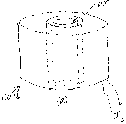
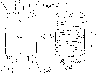
Consider a cylindrical permanent magnet which is magnetized along its axis as shown in figure 1a.
It is customary to described the PM as if it were a solenoid having many turns around the cylinder’s lateral surface and carrying an effective current Ia.
See figure 1b. In this case one can describe the PM’s field energy by the formula 1/2 Lm Iaa, where Lm is the effective inductance of the PM as if it were an actual coil carrying the current Ia.
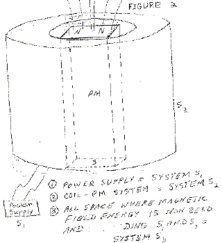
Now suppose that we put this PM inside a coil as shown in figure 2. We switch the coil on in such a way as to cancel the PM’s field. The field energy for this situation can be written as:
Wmag = 1/2 LmIaa + 1/2 Lc Iia – MIa Ii,
where Lc is the inductance of the coil, Ii is the current put into the coil, and M is the mutual inductance between coil and PM which is to be thought of as a solenoid.
When the coil is turned on, the PM acting as if it were really a coil driven by current Ia, should be aided by an induced emf so that the current Ia should increase. However, Ia is atomic origin and cannot be altered. Thus by the reciprocal relation which exists between coil #1 and permanent magnet acting as coil #2, this induced emf must end up in coil #1.
Therefore the induced emf acts to build up the current Ii.
This makes sense since we start with the magnetic field of the PM and end up with no or almost no magnetic field.
The field energy that disappears from the S3 system must appear in some other form.
Differentiating (1) with respect to time we get the input power
Pin – M+in = Lc Ii I+i – MIa I+i
It is seen that this can be negative if I1 and I+i vary within a certain range. From this we can compute the coil’s input voltage as
Vin = Lc I+i – MIa I+i / I1
If Ii = 0, W = 1/2 Lm Iaa and W+ = 0 so that no back emf can exist in an unexcited coil near a PM.
But if I+i > 0 the back emf Vback = – MIa I+1 / Ii begans to build.
In any practical demonstration of this effect, we must include the IiR drop so that
Vin = Lc I+1 + RI1 – MIa I+1 / Ii
gives the input voltage to the coil. For certain values of Ii and I+i, V1
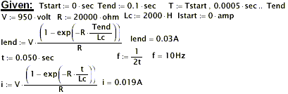
For a numerical example, suppose Ii goes from 0 to 30 ma in 0.1 sec.
If Lc = 2,000 H anr R = 20,000 ohms, then V= 2,000x.3 + 20,000x.03 – MIa x10.
We can only estimate x and Ia but typically Ia is tens of thousands of times Ii.
Further, M= …(unreadable) which itself is at least an order of magnitude.
Since we know that magnetic field energy disappears, we know that Vi must be negative and judging from the order of magnitudes of each of the terms in Vi, is itself at least three orders of magnitude.
Thus for the numbers given, we would expect the input power of between -30W to -300W or so. Thus Vii and I+1.
Also Pin = Lc Ii I+i + RI2i – MIa I+i
The interresting observation to be made is that the PM’s field in S3 can be ‘SHUT OFF’ by outputting its energy into the external circuit.
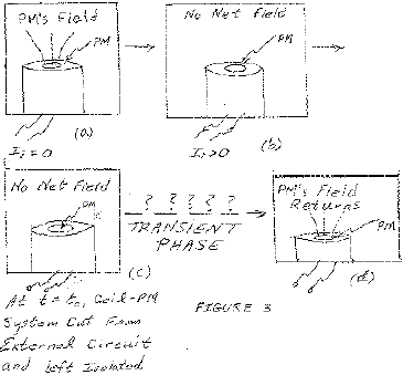
If at the same instant t0 the external circuit were removed, we have no closed circuit. However, we can predict the final result:
the PM field will again be present and the current in the coil will cease.
But how can the isolated coil-PM system S3 gain back the PM’s field energy when it has been cut from the external circuit?
The situation appears as in figure3. What happens in the transient phase?
From what we know about coils and back emf’s, something must happen within the coil that will allow the PM to again become uncovered; i.e. obviously the current in the coil will go to zero.
From an energetics point of view, a field of energy 1/2 Lm I2
Two cases occur: a/ The coil is shorted immediately upon removal of the external circuit; and b/ the coil is left open.
In either case the end results are the same: after transients, the PM’s field returns and the coil becomes passive.
In case b/, we need not worry about the coil’s I2R losses or about the coil itself during the relaxation process.
We can then think of this transient phase as follow: Imagine the coil to be a ferromagnetic sample and the PM is to act as a magnetizing agent.
The coil, acting as a ferromagnet, has a remnant field which at t0 just cancels the PM’s field.
As the transit process begins, the PM field must unmagntize the coil.
Remember, the coil is acting like a ferromagnet with a remnant field.
At the end of the process, the net field will be H0 which was what the PM’s field was before the coil was excited.
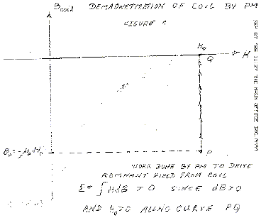
The graph for this process is as shown in figure4.
Clearly, the energy for this process is given by E … as it is in any magnetizing process.
For the curve shown, E = S … > 0, so that the PM is doing work ON the coil.
The energy required for the PM to so act on the coil comes from the Amperian circuital currenta or from the PM’s internal energy.
Hence, these circuital currents suffer an energy loss on an atomic level.
But it is impossible for the circuital currents to diminish because quantum conditions within the atom are far more stringent than the little perturbating force of the coil.
The loss of energy will then be drawn from the PM’s thermel energy on the level of … and within the PM itself.
The thermal energy of the PM will thus decrease and so the PM will cool.
This latter phenomenon occurs because we assumed that the PM does not change during the entire process; i.e. the coil’s field, on or off, does not alter the PM’s domain strucutre.
This is a fact which is known to be practically attainable.
Further, we can always choose a range of I1 values so that the whole process will lie on a Barkhausen jump where the B of the PM remains constant while the Hcoil changes provided the current Ii, so chosen, and its rate I+i, also lie in the negative input power range.
Also, by making the coil physically large, the remote part of the PM’s field can be canceled without … stress on the B field near the PM.
Thus large amounts of magnetic field energy can be canceled from the coil-PM system and this energy dumped into the external circuit without stressing the PM to change internaly.
The entropy of the PM will remain constant during the switch on process.
During relaxation however, the entropy of the PM will decrease because its internal energy will drop as it drives the ‘remnant’ field out of the coil.
Cooling means an entropy drop even though there is no change in the PM’s domain structure.
The PM will not drive the coil to positive magnetization since at Bcoil = 0, the coil becomes passive and all currents within the coil cease.
The final state, after transients, is of course, identical to the initial state.
Therefore this process can be repeated cyclically.
During each cycle an amount of heat Q will be absorbed by the PM so that it can remain in thermal equilibrium with the surroundings.
The entire cycle would require from 10 to 100 millisec. so that from 10 to 100 cycles can be made per sec.
The numbers chosen herein are typical of the orders of magnitude that i have experimented with.
Obviously, they are cot critical with the exception of the large coil because its relaxation time is long enough to switch off at time t0.
If the switch off time dt is of the same order of magnitude as the coil’s relaxation time, the negative power will be dissipated in the switch or retrieved by the coil from the external circuit.
Since the energy dumped into the external circuit is equal to the energy that disappears from the PM’s field, we can also calculate the ‘free energy’ directly from the part of the PM’s field cancelled.
If B0 is the value of the PM’s field, the energy of its field is given by
Emag = 1/2 u S E2 dv where the integral is over all space.
Far from the PM, B2 = B20 … unreadable formulas part …
Since the angular part gives… and u=10-2, and we are going to choose R0 to be a larger than the physical dimensions of the PM, we can write Emag = 2 Pi/ 10-2 B02 1/R0.
Using B0= 1w/m2, and assuming that the PM’s size is but a fraction of a meter so that R0 = … is far from the PM, we can estimate Emag to be 200 x Pi = 614 J.
If only 1/30 of this field energy is cancelled by the coil, about 20J. of energy will be dumped into the external circuit per cycle.
For 10 cycles per second, we get 200… output.
This means that Q=200… = 50 cal/sec will be the rate that the PM will draw in heat from the surroundings.
For a 100 lb. coil-PM system, we get 50 cal/sec = … or Delt T = 50/4994 oK/sec, where we have assumed an average specific heat of .11 cal/…
For an adiabatic process, the coil-PM system must suffer a temperature drop of 1/100 of a degree Celcius per second.
Operating adiabatically for five minutes should cause the system’s temperature to drop 3.0 oC.
Temperatures of this order of magnitude have been actually observed on the Electro-Entropic meter.
Of course, the meter’s coil=PM system was not thermally isolated so that a continual drop in temperature with time was not observed.
It struck me that when big coils were switched, sometimes very large arc back would occur at the switch and other times virtually no arc back was observed.
The previous discussion clarifies these qualitative behaviors.
For certain values of I … , the negative power was being lost in the switch other times it was not.
Of course, I was dealing with a rotating PM and was not controlling Ii or I+1 at all.
It was by chance that the correctcombinations of current , current rate, and cycle time were combined.
This explains why high efficiencies were measured only under certain operating conditions.
For the Electro-Entropic motor efficiencies of 2,000% were measured.
The measuring process was a no load situation and the … loadwas the accelerating 5 kg armature.
The cooling effect was also best noted under these operating conditions.
Also no regard was given to the polarity so that sometimes the motor operated by repulsion as in the Jones’ motor, and sometimes by attraction.
Clearly, negative power and cooling requires attraction between coil and armature.
Most of the tests made were with an eye toward repeatability.
I therefore used various input voltages, currents, and polarities without noticing what they were insomuch as I was getting the cooling effect repeatably.
Now I will renew this tests with an eye towards these differences.
Again, and for the record, the … motor has an efficiency of 20 to 1 in a no load situation.
I think this motor should be looked at by the Institute and this over unity effect can be verified first hand by you.
The ‘black box’ device was my attempt to do away with the moving armature of the motor.
As I mentionned, this device had an over unity efficiency for the two tests I performed.
Further tests are needed. However, from this device can be gleaned the arc-switch.
This switch and a few simple circuit components, can control I … and guarantee fast current off times.
Even solid state devices have difficulty in turning OFF large currents in short times.
The arc switch has a shut off time of 5 microsec for a current of 60 Amps as demonstrated on the scope.
## Analysis of Leon Dragone’s, “Energetics of Ferromagnetism”, By William S. Alek, INTALEK, INC., November 2002, Version 5a, from pdf file ‘DragoneAnalysis.pdf’
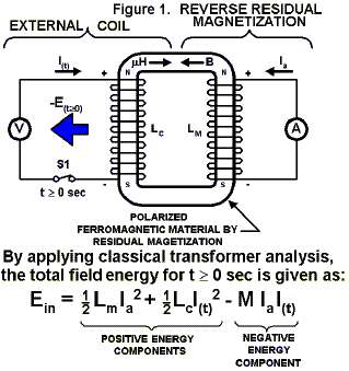
where, Lm is the virtual magnet inductance.
Ia is the virtual atomic current of magnet.
Lc is the inductance of the coil.
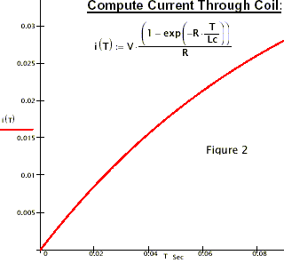
I(t) is the coil current.
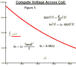
M is the mutual inductance of the coil/magnet system.
E(t>0) is impulsive output negative energy.
# COMMENTS:
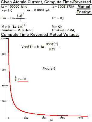
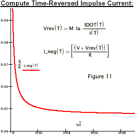
Referring to figure 1, the moment S1 doses (t=0 sec), a ‘negative ebergy’ impulse function occurs.
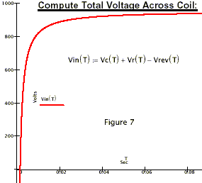
This also shown in figures 6 and 7 as a voltage impulse function.
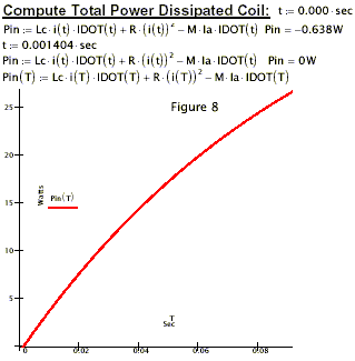
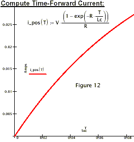
‘Negative power’ is produced during the time duration as shown in figure 8.
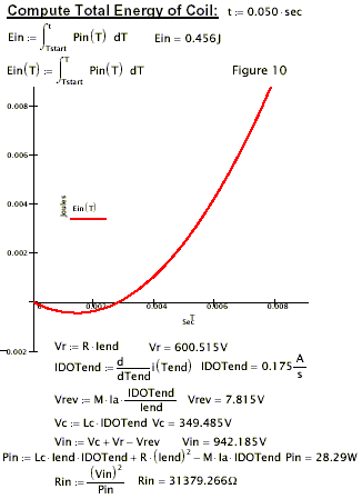
‘Negative Energy’ is sent back to the source as shown in figure 10.
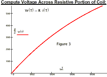
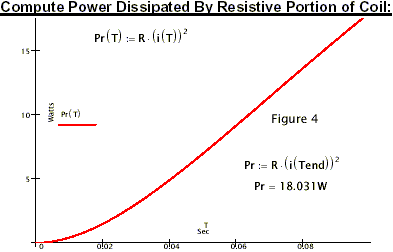
Because the coil is resistive, it will dissipate ‘positive energy’ as shown in figure 5. However. the total power (Pin) is negative as shown in figure 8.
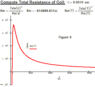
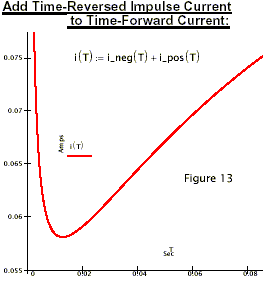
Figure 9 is of special interest because it exhibits a property I call ‘supermegativity’.