Page created June 2007
Bedini’s Oscillator Charger is based on a classic ‘self oscillating’ double coil circuit
by MDG
This kind of circuit, oscillating automaticaly, will create continuous sequences of ON and OFF magnetic fields in the coil arrangement ; then, each collapsing of these magnetic fields will induce a Back Electromotive Force in the third coil, wound together and of same length. This BEMF is of a higher voltage, in the hundreds of volts but with a very weak current that makes it un-exploitable. The trick of John Bedini, the same Edwin Gray, Thomas Bearden and others were using, is to send this high voltage pulses in a capacitor, through a bridge rectifier, because it works only with polarized capacitors. Then, the object of the patent of John Bedini, is to discharge regularly this accumulated high voltage potential in the capacitor in electrolytic batteries.
The high potential from the collapsing magnetic fields in the self-oscillator circuit, is made usable through charging of the capacitor (prove that capacitors don’t need current to charge them, but just Pure Voltage Potential is enough), then when the capacitor is discharged in the battery (or batteries bank), this high voltage pulses have a very special effect on the electrolytic batteries, increasing their capacity, making them fully charged in minutes, and even, after many cycles with this special charger, making them to self-charge, pumping directly the energy from the environment.
It works ! Many replications, like mine, are working very well. It is very interesting to improve the use of standard batteries, and it is a solution to the problem of discarded polluting batteries. A dead battery will be rendered ‘better than new’ within may be 2 dozen of charging-discharging cycles with this kind of system.
It has taken 20 years to see this kind of charger on sales, but now it is available through the company ENERGENX (see article below) that exploites John Bedini’s patent. Like it is supervised by John we can be sure to find a ‘top level’ product with optimum performance and manufacture quality production. We must send our thanks and congratulations to John and this team for bringing to the market one of the first Radiant Energy product. We hope that it will be a large success and the first of a long series, bringing free electric power to the world.
Because this Radiant Charger could help millions of suffering people all over the world, we could expect that a special ‘free license’ to manufacture it in undevelopped countries will be accorded; because the population of at least 100 countries in the world just CAN’T AFFORD to buy one Bedini Charger at a cost superior to a few hundred dollars. And because we are sure that this company can already make MILIONS OF PROFIT in the developped world … where anyway they won’t be able to answer alone to the large demand of hundreds of thousands customers!
So why not just forget the eventual profit that could be made in the third world countries, and concentrating on the rich countries market. Anyway we can imagine that it would be very difficult and costly for an US company to sue the hundreds of small enterprises that could produce small quantities of this patented charger, in their miserable city slums, where there is no law enforcement and danger at every corner.
My personal opinion is that EQUITY should be practiced in our world, meaning that those who can afford should pay full price for it, and those who can’t afford should have a special derogation, giving them the right to access to modern technologic development, even if they have no money. EQUITY IS THE BEST ! I encourage all of you to become more generous, and to think about those who have less chance than you, and how you could help them … Love, Peace and Equity … What a wonderful world.
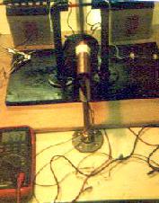
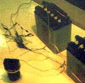
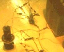
My replication of Bedini’s Oscillator Charger
by MDG
I spent USD 12 to build and see a Bedini Solid State Charger, and the results are very positive, because it rejuvenated dead batteries, and because it demonstrated to me the existence of Radiant Energy …
I followed the diagrams found in the ‘Free Energy Generation’ book of Mrs Bearden and Bedini. Like I can’t afford the USD 50.00 they ask for, it’s from a friend that I get them. Yes, USD 50.00 is a big amount where I live, and believe it or not, THERE ARE PEOPLE WORKING A FULL MONTH TO GET USD 50.00. And that’s not just a few people concerned, but HUNDREDS OF MILLIONS. Yes, every ‘western world’ inhabitant is considered as a very rich and unreachable person for us. Try to give it a thought or two …
– Couldn’t get SCR so I made a simple circuit with a transistor driven by a 555 timer for the capacitor discharging part;
– The Capacitor is an old rusted 10 microFarad 400 Volts from Air Cond. spare parts shop.
– The larger part of the budget was for the wires for the Trifilar coil; I use Gauge 22, 3 lengths of 30 meters (3 x 100 feet), wound around a bunch of 8 welding rods inserted in w White Electrician Plastic Pipe diameter 20 mm (3/4 inch), and 100 mm long (4 inch.). I didn’t count the turns, but I took care to have the 3 wires of the exact same length, and wound quite properly together.
– As transistors I used what I had already (see diagram)
– I get the Opto-isolator from a discarded Computer Power Supply. It separates High Voltage Circuit from Low Voltage one.
– I used a power source; one for the oscillator circuit, and one for the 555 timing circuit and the Opto, because connecting the 555 to the oscillator supply stop it from working (I use an old 12V laptop battery for the timing part). The 555 doesn’t like HV spikes !
– The Charged battery was a discarded one, showing 1.7 Volt.
zpe_bedini_mdg_solid_charger.gif
I burnt a few potentiometer to look for the sweet spot of the assembly oscillator – capacitor.
I adjusted the charging/discharging cycle of the capacitor at around 2 seconds of charging and 1/3 second for discharging. Resistor values: R1 = 100 Ohm ; R2 = 34 kOhm ( 50 kOhm potentiometer)
In two second the Cap go to arouns 130 Volts, and then is completely discharged in the battery
A dead car battery showing 1.7 Volts, get fresh in just a few cycles, and then I could take each time more power from it, till it became better than my other ‘not dead’ battery. See the testimonial of the Renaissance Charger 2A12 on the Energenx page, for an example more detailed (link in Bedini’s menu on top).
What surprised me also was the high voltages I could read in DC an AC on my voltmeter, in different parts of the circuit.
While using 12 V 6 A power supply from the wall, directly connected to the input of the circuit, I could read fluctuating voltages up to 2,000 Volts ! When a car battery is connected between the power supply and the circuit, the battery receive this high voltage pulses, and it starts to charge also, becoming quite hot after a while. That battery wouldn’t take any more charge from the power supply alone, being already at a higher voltage.
Also if I was to put the negative electrode of my voltmeter on the aluminium sink of the transistor in the self-oscillator part, it would show also peaks up to 2,000 Volts ! With on wire connected only !
An interressant fact also, is that the plastic on the top of the battery processed whit such a charger, becomes conductor … and from plastic to plastic you get voltage reading, up to 5-6 Volts. From one lead connector to the plastic also you read voltages. It’s the effect Bedini shows in his DVD, ligthning an red LED connected on plastic to plastic ! That is quite unusual, but easy to reproduce ! Something to show to your teacher !
The last one is that while running the circuit, you can get voltage on everything around the charger; small voltage reading on plastics, and higher on metals. That proved me that some energy was attracted from around, and on its way you could ‘see’ it …
Oh ! I forgot the best ! While running comparative tests on different size of capacitor, to look for the one charging to higher voltage (almost all the same results), I get to burn out my 5 ko potentiometer used to adjust to the sweet spot, and what happened !? The circuit started to smoke a bit, and to show nuch higher voltages reading on the capacitor, in the 400 to 1,000 Volts ! So I get a bit scared and disconnected the power supply .. with NO EFFECT ! THe circuit was stil ‘running’ alone, WITH NO INPUT !! It ran for a few minutes like that, and I could see the voltages going randomly from 20 to 1,000 Volts, charging the capacitor. A few times I shorted out the capacitor, getting the usual fat spark, and the circuit charged it again and again. That’s amazing.
Of course I just can’t explain what happened, but it was for real. After playing a few minutes I stopped it, and had no time since to give it another try. To weird for me !
So my opinion is that we could much more than a Radiant Energy Charger from such a Self-Oscillating Trifilar circuit, and may be Bedini still keeping some secrets for himself, waiting to see if somebody is smart enough to find them …
Of course the original diagram from the book should even work better, and the Marketed Chargers by ENERGENX must be uncomparable in results and fiability, because of the expertise of the numerous specialists of Radiant Energy involved in their conception.
Mine was just a personal attempt to verify the veracity of the facts anounced … YES IT WORKS, and even beyond what is expected. Congratulations to the inventor.
From the Patric Kelly pdf file ‘D3’
http://panacea-bocaf.org/files/patrickkelly/D3.pdf
… Recently, John Bedini has collaborated with Tom Bearden to produce a very important book “Free Energy Generation – Circuits and Schematics”. I strongly recommend that you buy a copy of this book as the contents are vital. Copies can be bought via http://www.cheniere.org and there is also a very important DVD by Tom Bearden entilted “Energy from the Vacuum” which I also recommend that you buy. …
… This is a circuit for capturing zer0-point energy. There are no moving parts and only one simple coil needs to be wound since all of the other parts are readily available electronics components. The circuit operates by charging a capacitor to a high voltage and then discharging it suddenly. This sudden discharge creates conditions where the local environment feeds large amounts of free energy into the circuit. This energy is ‘cold’ electricity or ‘negative’ electricity and it acts in the opposite way to our everyday ‘hot’ electricity. Items such as resistors, transformers, coils, tec. which cause losses in a circuit driven by ‘hot’ electricity, act in exactly the reverse way for ‘cold’ electricity and actually gather additional energy into the circuit from the surrounding environment.
It would not be unusual for the circuit shown below to have an input of just 200 milliamps and yet generate an output power of 300 kilowatts. The overall strategy is to have the circuit powered by a battery, and arrange for the circuit to charge a bank of batteries which can then be used to drive equipment and power other loads. A circuit of this type can reasonably be expected to have a COP (energy policeman, Coefficient of Performance, i.e. Power Out/Power In) ot anything from 20 to 100.
The rate of charging of the output batteries increases gradually over a period of a week or so, and eventually the batteries should be charged about 50 times faster than is possible with conventional ‘hot’ electricity. The circuit looks very simple, and indeed it is simple to build, but do not be fooled into thinking that it is a normal circuit – it isn’t.
This circuit is designed to capture external energy and its design is based on an understanding of exactly what the zero-poit energy field is, how it operates and how to capture it. This circuit can run continuously day and night. In fact, it actually operates slightly better at night, due to reduce interference from other energy sources.
Because of many complaining e-mails received from ENERGENX Inc., Cheniere Press, etc…, Mr Patrick Kelly has been forced to take out from his files the Diagram of the Bedini Solid State Oscillator Battery Charger.
As I don’t want to create more trouble to Mr Kelly originating this files, I took these diagrams and explanations out of this page also.
In place I inserted an article I wrote when learning about this censure by Mrs Bearden/Bedini and Co.
Note: Before you read what follows, I must insist that I respect the great work done by Mr. Bearden and Mr. Bedini in the Zero Point Energy field, that wouldn’t be so far developed without their efforts, but I can’t keep silent when they decide to use their discoveries to make money, when it could save so many lives. What is the price of an human life for you ? That is what it is all about. Free Electricity CAN save and improve the life of suffering people, so it MUST ALL BE public domain knowledge ; money has no value when a life is in the balance, no ?
How can you spend 30 years of research to offer Free Electricity to the world, and when you start to publicize the solutions you found, you also stop to give any free information as how to reproduce this solutions, while also restricting the production to specific financially selected companies.
In the world where I live, where you live, daily, the MAJORITY of the humans present here with us, SUFFER. They suffer because of a lack of means to develop their life like you western world had the chance to do 50 years ago. How can you think about your own personal luxuous comfort when you know how the situation is ?!? Do you have any heart beating in your chest, or is there only a money counter ?!?
How can you say ‘We have a super solution to an enormous problem’, but ‘The use is restricted to rich people only’. Yes it is business, but are we here only to do business, and think about a big car, a big house, and a big bank account ?! Does God created you to enjoy egoistically life on earth ?! Won’t you reach one day the end of this short life on earth ?! Won’t you go and meet your Lord face to face ?!
To you, He gave a very special knowledge that can diminish suffering of billions of your human neighbors just for you to be rich and have a big estate ?!? I don’t think so..
Please tell me how you are going to win your place in Paradise when you are just wasting this exceptional chance to change the life of billions of people, by restricting the use of your product to uper classes only !?!
I mean we are just creatures on this hearth, most of us are living like sheeps, just following the group, and you, Mrs Bedini, Bearden and co, that get the chance to be able to collect enormous rewards trhough the knowledge that God sent you, you choice just to do business with it !
I mean it’s your chance ! Your chance and your responsability in front of God, to show him how grateful you are for this exceptional destiny, and that you understood His volonty, that is also to help the less fortunate.
I encourage all of those who have this kind of VITAL technologies to offer it to those that need it the most, and to do business with it, where people can afford to buy it. YOUR INVENTION IS NOT YOURS, ALL KNOWLEDGE BELONGS TO THE CREATOR OF THIS WORLD, and it should be used for the release of the oppressed.
I hope you will agree and finda ‘deal’ to allow undeveloped countries to use your technologies for free. Just because it’s important and because I know you don’t realize HOW HARD is the situation there, in the misery. (have you ever visited a Slum, a Favela or a Jungle Village to see the living conditions ? No electricity = no light, no tap water, no refrigerator, no wind fans, no heaters, no cooking apparatus, no workshops, no machinery for agriculture or industry, no nothing!)
Hope this help, Love and Peace. MDG
Opinion, Free Energy, the Lobby or the Family?
Posted on Sunday, August 26, 2007 @ 22:43:59 PDT by vlad http://pesn.com/2007/08/26/9500494_Energy_Lobby_v_Family
A man who learned and is now sharing a way to rejuvenate 12-volt batteries to keep from having to buy new batteries, which is helping third world denizens survive, bemoans the request that has come from the copyright holder to remove this information.
by Fredo Strando, aka M.D.G., for PES Network News
Hello, as webmaster of http://waterfuel.100free.com , I’m confronted by a disturbing problem of consciousness in my quest to locate solutions to problems that the world is facing.
I want and try to help the poor, those who have almost nothing, and to help the planet that is quite illiterate now, to make a better world to live in, for everybody.
My Family, those who are suffering from neglect and lack of means, the poor and miserable, need cheap energy, food, education, and cheap construction material. The planet can not support all of our pollution and destructive rejects any longer.
Actually many solutions have been discovered already, to produce cheap, renewable electricity, to pump water with little power from deep wells, to desalinate or purify water at cheap cost, to heat or cool simply, or to produce more yields in the fields. But this knowledge is in the hands off powerful persons or companies that don’t authorize us to use it!
That’s the Lobby, the greedy, the smelly side of the problem.
I write this article today because I have been one more time confronted by the Lobby while trying to help the Family, and this time from a source I would not have expected
A few months ago I found on an honest and friendly website, a diagram of a ‘free energy generator’ that seems actually not to be able to deliver so much ‘free energy’, but that can be used to answer a big problem that faces the Familly, and the Planet also.
It’s the ‘solid state oscillator/generator’ from John Bedini, published by Thomas Bearden cheniere.org http://cheniere.org/ , company, divulged in their latest book ‘Free Energy Generation’. I posted it on my website at http://radiant.100free.com/zpe_bedini_solid.html
We found this system could regenerate a ‘dead’ car battery within one night, by pulsing ‘high voltage cold electricity pulses’ in the battery. After 12 hours under this diet, a battery showing 1 or 2 volts, that wouldn’t keep any charge, will then ‘work’ again, and hold a mighty 12 volts or more — for weeks!
With this ability, it become unnecessary to discard old batteries and buy expensive new ones. The system is easy to manufacture, and it uses only a few watts of power. A ‘batteries recycling shop’, equipped with these pulse/chargers could bill the customers only one tenth the price of a new battery to ‘rejuvinate’ a dead battery.
This is a very good thing when we know about the millions of ‘old’ batteries that are thrown in the wild every year, polluting the ground and underground of our beautiful planet, with acid, plastic and lead.
The Family, to whom it is a heavy expense on the already small budget to buy a new battery, could then save 90% of this cost, by just going to the ‘battery recycling shop’ at the corner.
Yes, it’s a great discovery, thanks to the genial inventor John Bedini, who in the past was proud to call himself a humanitarian, worrying for the old lady at the end of the line, with the menial budget. These plans were posted on his website for many years.
BUT it was too good to last. The Lobby was there, behind, waiting to jump on the Family helper!
Yes, the friendly guy that published this helpful diagram on his website (I won’t give his name by discretion), received a complaint from the ‘owners’ of this knowledge, the book editor, cheniere.org http://cheniere.org/ , and removed the saving device from the view of those that can’t afford to buy the book.
The humanitarian that wanted to help the old lady, 30 years ago, now wants money for it. COPYRIGHT, they say! Can’t use it for free!
And they forced the nice guy to take the diagram off of his website, which he did. And he sent me e-mails asking me to do the same, or at least to take out the link to his original document.
So there comes the question: Free Energy, the Lobby or the Family?
Should I respect the Lobby and their copyright claim, and remove this useful knowledge from my website, or should I choose the Family, and keep the information there for them to use it?
I’ll ask you, is there any real humanitarian here, that after discovering an important thing will give it REALLY free for mankind?
Yes, there are some, including in the free energy domain, thanks God; but for those two B and B that claim to WANT and to KNOW HOW to change the world for the better, I have to wonder about their sincerity or understanding of the meaning of the words ‘humanitarian’, ‘giving’ and ‘compassion’.
Money changes everything, the poor guy with a big heart too often becomes greedy when rich!
So I will ask you in straight terms, Mr. Bearden and Mr. Bedini; what about your discoveries in free energy production, are they for the Family, or are they already in the hands of the Lobby?
Thank you for your consideration, with hope for the best end. For a better world in which to live.
Feedback: Open Information and Royalties Both:
On Aug. 23, 2007, Sterling D. Allan wrote:
The problem is that in the developed world, people ought to pay for the information they receive which is of substantial benefit to them. It is not unreasonable that the person responsible for that information expects that if someone is benefiting commercially that they (the originator) should get a commensurate piece of the action.
Perhaps the compromise position would be to make the information available free of charge for individual builds, but if someone begins a commercial operation, they should pay a small royalty to the originator of the information; and even those who build just one device should provide some small payout to the design originator if they can.
A memo to that effect at the beginning of the page containing such information should be an adequate good faith measure that honors both the needs of the poor as well as honoring the needs of the inventor and developer, who deserves to be compensated for the information they provide.
Comments on the article: Free Energy, the Lobby or the Family?
Posted on Sunday, August 26, 2007 @ 22:43:59 PDT by vlad http://www.zpenergy.com/modules.php?name=News&file=article&sid=2525
Re: Free Energy, the Lobby or the Family? (Score: 1), by Xels on Monday, August 27, 2007 @ 01:45:41 PDT
I personaly built and currently own/operate one of John Bedini’s motor/generators. It uses radiant scalar energy that causes the batteries to charge themselves. In the meantime you receive free mechanical work from the collapsing magnetic fields. Tesla was the one who first discovered the type of energy that Bedini’s devices produce. It’s all very cool stuff.
Re: Free Energy, the Lobby or the Family? (Score: 1), by Koen on Monday, August 27, 2007 @ 10:33:04 PDT
Forget the lobby for a while, focus on the family. It is possible for anyone to order a radiant battery charger: http://www.energenx.com/research.htm (MDG nov07: see also dedicated page on this website, in Bedini’s menu on top)
The radiant battery charger charges a battery (bank) with voltage pulses rather than with a charging current, according to John Bedini. An extraordinary claim for which standard electrodynamics theory has no explanation.
Only my extended theory of electrodynamics with scalar field seems to explain much of its operation.
Most batteries show a leak current, some a big one, some a small leak current, that is slowly discharging the battery. I think Bedini’s trick is to induce an inverse (charging) “leak” current that is totally internal and which is not flowing through the external charging circuit at all.
By applying a voltage pulse on the charge that is already inside the battery, one delivers also a scalar field type of power equal to P = dV/dt Q, where dV/dt is the change in voltage per second and Q is the static charge in the battery. The bigger the voltage change per second and the bigger the battery charge, the bigger the induced scalar field power. John explained that the voltage pulses, characterised by dV/dt are some sort of ‘radiant’ scalar field, and that is absolutely correct.
The static charge Q is extra potentialised by the voltage pulse V.
Inside the battery this ‘cold’ type of energy is converted into a ‘hot’ type of power which we know as P = IV (the product of current and voltage).
This means that the voltage of the ‘over-potentialized’ charge drops back to the nominal battery voltage (slightly above 12 volt), and meanwhile the battery charge is electrically polarized by an internal (unmeasurable) reversed leak current I. This energy conversion is called ‘regauging’ by Tom Bearden, but this physical gauge process has nothing to do with the ‘formal’ gauge conditions of electrodynamics theory.
John Bedini’s radiant charger uses voltage pulses with peak voltages much higher than conventional battery chargers. Secondly he shows that it is better to charge many batteries (that contain much Q) simultaneously with one radiant battery charger. This is in perfect agreement with power term P = dV/dt Q.
Static electric energy is equal to E = VQ, so electric power is equal to
P = dE/dt = d(VQ)/dt = dV/dt Q + V dQ/dt = dV/dt Q + VI.
Official science has shunned power term dV/dt Q because of the Lorentz gauge condition. But since this condition is totally artificial and theoretical, one should doubt it in favour of further experiments that prove or disprove the physical relevance of scalar field expression dV/dt.
The radiant pulse energy flow, associated with dV/dt (abrupt voltage change per second), is simply proportional to dV/dt grad(V) which is the “Poynting” vector of a longitudinal electro-scalar wave travelling from charger to the battery bank. If we call S = -dV/dt the scalar field, and E = -grad(V) the electric field, then the energy flow vector is simply ES, quite similar to the energy flow vector ExH for transversal electromagnetic radiation.
I also assume that the ZPE background energy field can have the form of longitudinal electro-scalar waves (as shown by E.T. Whittaker), and that static charge is always in energy balance with the ZPE vacuum.
My simple theory shows that much of the terminology used by John Bedini can be expressed in exact mathematical terms.
The proven fact that the radiant battery charger also restores the battery ‘health’ is a wonderful extra bonus. Just order the radiant charges, and begin experimenting.
ENERGENX Inc. – Battery Charging Solutions That Make A Difference
(Score: 1), by vlad on Sunday, August 26, 2007 @ 22:47:18 PDT
ENERGENX, INC. has developed core technologies based on an electromagnetic hybrid motor/generator, and on a new methodology for an improved charging process for batteries. This technology is used for the development of new energy supply systems, battery charging systems, and a new generation of electrical motors/generators. The hybrid motor/generator utilizes a scientific concept which has been named Back EMF Permanent Electromagnetic Motor/Generator by the inventor, John Bedini…
Site: http://energenx.com/about us.htm [energenx.com]
Butler claim of Overunity using Bedini principles
KeelyNet – 11/28/04 http://www.keelynet.com/energy/emmettou.htm
This was sent to the KeelyNet Interact discussion list on 11/26/04, with photos which the list cannot accept. So I cleaned them up as best I could and am posting in this file so everyone can see what Emmett referenced.
Good Afternoon All,TO START:I believe O.U. does indeed exist.
There are some different ways to do this, some simple, and a little energy – some a bit, how shall I say more complex, but unbelievable amounts of energy, I know, been there and have done it.
HERE IS A SIMPLE WAY TO ACHIEVE THIS!!!!!
BUT FIRST; As I always give credit where credit is due, first and foremost to John Bedini for his motor/energizers, Tom Bearden for the math and help in seeing what isn’t always obvious, on his website, to my friend, Stan Mayer, for thoughts, encouragement and how to do things with what few electronic parts are available in my area, i.e. Radio Shack, and to all the greats before me, Maxwell, Faraday, Stubblefield and especially Tesla.
NOW ON TO BUSINESS: I will provide a brief description and as you all can see there are photos, and if any are in my area or want to come to my shop, I will be glad to let you see, tinker and photograph to your hearts desire, on this project anyway.
1). We will start with Johns’ school girl energizer (simplified) first. There are many of you out there that I know of that have achieved minor o.u. in the .01 – .1 – .2 volt range for periods of time, there are those of you who have achieved a 1-1 unity, i.e., trading the same voltage back and forth between batteries over time and the voltage does not go up or down although in practical situations (not this) it would normally go down over time due to resistance in the wires, resistance in the bearings, air resistance of the rotor rotating, and general quality of workmanship, there are those of you who are close to 1-1 unity but are only losing .1 – .3 volts over a 24 hr. period, that is good too, but not good enough but not to worry.
I have included in the pictures, photo1, of my SG energizer, “the black widow” so you can see all the wires and circuitry etc. nothing hidden, nothing magical.
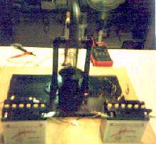
Photo #2. rear view with a small coil with a screw through the center attached to a copper/PVC pipe stand, the leads are attached to a home-made 4-diode, simple full wave bridge rectifier, (4) IN4003 diodes, or a standalone manufactured one will work also with a cap. connected across to smooth out the spikes.
I originally used a reed switch but they have a tendency to burn shut and last only so long, so I asked my buddy, Stan Mayer, what I could substitute, thanks Stan. Yes I know the pictures are dark, using an old Polaroid Instamatic, flash burned out, but I wanted pictures, NOW, you will notice that the leads from the fullwave bridge rectifier are connected to a DVM and it reads 6.13 volts.
Now this little coil is made from a screw about an inch long and 3/16″ in dia. wrapped with radio shack 28g wire about 200′ worth. This is far in excess of those who are losing .1 – .13 volts every 24 hrs or so O.U. IN MY BOOK…BUT IT GETS BETTER.
Photo # 3. is just a side view.
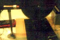
Photo #4. now some of you have found that you don’t need your wheel to rotate at all, that by just stacking your magnets on top and a few adjustments it becomes a resonate circuit and some of you are finding that it is still charging your batteries, both input and output at the same time, this is more than possible, Stan explained how the electronics do indeed do this through a little window in time (pun intended).
Picture #4 is mine doing just that BUT IT GETS EVEN BETTER!!!!!!!!!!!!!!!
NOT ONLY DO YOU NOT NEED A ROTOR ROTATING, YOU DON’T NEED MAGNETS TO MAKE IT RESONATE, JUST ANOTHER COIL, photo #5, show my coil sitting on top, it is smaller than the main coil, so needed to get it closer, although side by side it will still provide a voltage, just not as big, now!!
1, if you make your coils larger, the same size and attach the circuit I described above, you not only achieve O.U. in charging the two batteries, but you can run extra voltage even above, the DVM reads 2.579 volts in case you can’t see it.
SO NOW YOU NOT ONLY HAVE O.U., IN ONE SYSTEM BUT A SECOND SYSTEM AND THERE IS NO MOVEMENT, POSSIBLY A SIMPLIFIED MEG WITH SIMPLIFIED STUFF, BUT I CAN’T NOT SAY FOR SURE, EITHER WAY IT IS A NON-MOVING GENERATOR THAT YOU ALL CAN BUILD EASILY IN A COUPLE OF HOURS!!!!!!!!!!!!!!!
I ask only one or two things, PLEASE, tell and send this to all your family, friends, other energy sites, Rense.com , papers, radio, tv, or whatever as the momentum needs to raise sharply, like the spike on a scope of radiant energy as some have seen, or this will die a very quick death and my other peripheral devices along these lines are not worth putting out and I shall go into quiet retirement. ALSO.. any who want to come to my office and shop to see, tinker, experiment, and photograph etc. are more than welcome, I have NOTHING TO HIDE. my address is
Westwood/’Westside Apts. Office, 1015 Oakcrest St. ; Iowa City, Iowa ; 8-6 or so Mon.,-Fri. ; and about 9:30 1:00 or so on Sat.
Best Regards, Emmett L. Butler
USP 2003/0117111 A1
Jun. 26 2003, Device and Method for Pulse Charging a Battery and for Driving other Devices with a Pulse, John C. Bedini, Coeur d’Alene, ID (US).
Abstract: A two-phase solid-state battery charger can receive input energy from a variety of sources including AC current, a battery, a DC generator, a DC-to-DC inverter, solar cells or any other compatible source of input energy.
Phase I is the charge phase and phase II the discharge phase wherein a signal or current passes through a dual timing switch that controls independently two channels dividing the two phases.
The dual timing switch is controlled by a logic chip or pulse width modulator. A potential charge is allowed to build up in a capacitor bank, the capacitor bank is then disconnected from the energy input source and then pulse charged at high voltage into the battery to receive the charge.
The momentary disconnection of the capacitor from the input energy source allows for a free-floating potential charge in the capacitor. Once the capacitor has completed discharging the potential charge into the battery, the capacitor disconnects from the battery and re-connects to the energy source thus completing the two-phase cycle.
Technical Field:
(0001) The invention relates generally to a battery pulse charger using a solid-state device and method wherein the current going to the battery is not constant. The signal or current is momentarily switch-interrupted as it flows through either the first channel, the charge phase, or the second channel, the discharge phase. This two-phase cycle alternates the signal in the two channels thereby allowing a potential charge in a capacitor to disconnect from its power source an instant before the capacitor discharges its stored potential energy into a battery for receiving the capacitor’s stored energy. The capacitor then disconnects from the battery and re-connects to the power source upon completion of the discharge phase, thereby completing charge-discharge cycle. The battery pulse charger can also drive devices, such as a motor and a heating element, with pulses.
Background and prior Art:
(0002) Present day battery chargers use a constant charge current in their operation with no momentary disconnection of the signal or current as it flows either: 1) from a primary energy source to the charger; or 2) from the charger itself into a battery for receiving the charge. Some chargers are regulated to a constant current by any of severals methods, while others are constant and not regulated. There are no battery chargers currently in the art or available wherein there is a momentary signal or current disconnection between the primary energy source and the charger capacitors an instant before the capacitors discharge the stored potential energy into a battery receiving the pulse charge.
The momentary current interruption allows the battery a short ‘rest period’ and requires less energy from the primary energy source while putting more energy into the battery receiving the charge while requiring a shorter period of time.
Summary of the Invention:
(0003) One aspect of the invention relates to a solid-state device and method for creating a pulse current to pulse charge a battery or a bank of batteries in which a new and unique method is used to increased and preserve for a longer period of time the energy stored in the battery as compared to constant-current battery chargers. The device uses a timed pulse to create a wave form in a DC pulse to be discharged into the battery receiving the charge.
(0004) One embodiment of the invention uses a means for dual switching such as a pulse width modulator (PWM), for example, a logic chip SG3524N PWM, and a means for optical coupling to a bank of high-energy capacitors to store a timed initial pulse charge. This is the charge phase, or phase I. The charged capacitor bank then discharges the stored high energy into the battery receiving the charge in timed pulses. Just prior to discharging the stored energy into the battery, the capacitor bank is momentarily disconnected from the power source, thus completing the charge phase, and thereby leaving the capacitor bank as a free-floating potential charge disconnected from the primary energy source to then be discharged into the battery. The transfer of energy from the capacitor bank to the battery completes the discharge phase, or phase II. The two-phase cycle now repeat itself.
(0005) This embodiment of the battery pulse charger works by transferring energy from a source, such as an AC source, to an unfiltered DC source of high voltage to be stored in a capacitor or capacitor bank. A switching regulator is set to a timed pulse, for example, a one second pulse that is 180 degrees out of phase for each set of switching functions. The first function is to build the charge in the capacitor bank from the primary energy source; the second function is to disconnect the power source from the capacitor bank; the third function is to discharged the stored high voltage to the battery with a high voltage spike in a timed pulse, for example, a one second pulse; and the fourth function is to re-connect the capacitor bank to the primary energy source. The device operates through a two-channel on/off switching mechanism or a gauging/re-gauging function wherein the charger is disconnected from its primary energy source an instant before the pulse charger discharges the high-energy pulse into the battery to be charged. As the primary switch opens, and visa-versa in timed pulses to complete the two phase cycle.
(0006) The means for a power supply is varied with several options available as the primary energy source. for example, primary input energy may come from an AC source connected into the proper voltage (transformer); from an AC generator; from a primary input battery; from solar cells; from a DC-to-DC inverter; or from any other adaptable source of energy. If a transformer means is the source of primary input energy, it can be a standard rectifying transformer used in power supply applications or any other transformer means applicable to the desired function. For example, it can be a 120-Volt to 45-Volt AC step-down transformer, and the rectifier can be a full-wave bridge of 200 volts at 20 amps, which is unfiltered when connected to the output of the transformer. The positive output terminal of the bridge rectifier is connected to the drains of the parallel fiel-effect transistors, and the negative terminal is connected to the capacitor bank negative.
(0007) The Field Effect Transistor (FET) switches can be IRF260 FETs, or any other FET means to accomplish this function. All are in parallel to achieve the proper current of the pulses. Each FET may be connected through a 7-watt, 0.05-ohm resistor with a common bus connected through a 240-ohm resistor to a commun bus. There also may be a 2K-ohm resistor between the gates and the drain bus.
(0008) A transistor means, for example an MJE 15024 transistor, as a driver for the gates, drives the bus and inturn, an optical coupler drives the driver transistor through the first channel. A first charging switch is used to charge the capacitor bank, which acts as a DC potential source to the battery. The capacitor bank is then disconnected from the power rectifier circuit. The pulse battery charger is then transferred to a second field effect switch through the second channel for the discharge phase. The discharge phase is driven by a transistor, the transistor driven by an optical coupler. With a second or discharge switch on, the capacitor bank potential charge is discharged into the battery to receive the charge. The battery receiving the charge is then disconnected from the pulse charger capacitor bank to repeat the cycle. The pulse charger may have any suitable source of input power including: 1) solar panels to raise the voltage to the capacitor bank; 2) a wind generator; 5) a DC-to-DC inverter; 4) an alternator; 5) an AC motor generator; 6) a static source such as a high voltage spark; and 7) other devices that can raise the potential of the capacitor bank.
(0009) In another embodiment of the invention, one can use the pulse charger to drive a device such as a motor or heating element with pulses of energy.
Brief Description of the Drawings
(0010) FIG.1 is a schematic drawing of a solid-state pulse charger according to an embodiment of the invention.
(0011) FIG.2 is a schematic drawing of a conventional DC-to-DC converter that can be used to provide power to the pulse charger of FIG.1 according to an embodiment of the invention.
(0012) FIG.3 is a schematic drawing of a conventional AC power supply that can be used to provide power to the pulse charger of FIG.1 according to an embodiment of the invention.
(0013) FIGS.4A-D are schematic drawings of other conventional power supplies that can be used to provide power to the pulse charger of FIG.1 according to an embodiment of the invention.
(0014) FIG.5 is a block diagram of the solid-state pulse charger of FIG.1 according to an embodiment of the invention.
(0015) FIG.6 is a diagram of a DC motor that the pulse charger of FIG.1 can drive according to an embodiment of the invention.
(0016) FIG.7 is a diagram of a heating element that the pulse charger of FIG.1 can drive according to an embodiment of the invention.
Detailed Description of the Invention:
(0017) An embodiment of the present invention is a device and method for a solidstate pulse charger that uses a stored potential charge in a capacitor bank. The solidstate pulse charger comprises a combination of elements and circuitry to capture and store available energy into a capacitor bank. The stored energy in the capacitors is then pulse charged into the battery to be charged. In one version of this embodiment, there is a first momentary disconnection between the charger and the battery receiving the charge during the charge phase of the cycle, and a second momentary disconnection between the charger and the input energy source during the discharge phase of the cycle.
(0018) As a starting point and an arbitrary method in describing this device and method, the flow of an electrical signal or current will be tracked from the primary input energy to final storage in the battery receiving the pulse charge.
(0019) FIG.1 is a schematic drawing of the solidstate pulse charger according to an embodiment of the invention. As shown in FIG.1, the primary input energy source to the pulse charger is a power supply 11, examples of which are shown in FIGS.2, 3, 4A-4D. A 12-volt battery, as a low voltage energy source 12, drives a dual switching means of control such as a logic chip or a pulse width modulator (PWM) 13. Alternatively, the voltage from the power supply 11 may be converted to a voltage suitable to power the PWM 13. The PWM 13 may be an SG 3524 N logic chip, and functions as an oscillator or timer to drive a 2-channel output with ‘on/off’ switches that are connected when on to either a first optical isolator 14, or in the alternative, to a second optical isolator 15. The first and second optical isolators 14 and 15 may be H11D3 optical isolators. When the logic chip 13 is connected to a first channel, it is disconnected from a second channel, thus resulting in two phases of signal direction; phase I, a charge phase, and phase II, a discharge phase. When the logic chip 13 is switched to the charge phase, the signal flows to the first optical isolator 14. From the optical isolator 14, the signal continues its flow through a first NPN power transistor 16 that activates an N-channel MOSFET 18a and an N-channel MOSFET 18b. Current flowing through the MOSFETs 18a and 18b builds up a voltage across a capacitor bank 20, thereby completing the charge phase of the switching activity. The discharge phase begins when the logic chip 13 is switched to the second channel, with current flowing to the second optical isolator 15 and then through a second NPN power transistor 17, which activates an N-channel MOSFET 19a and an N-channel MOSFET 19b. After the logic chip 13 closes the first channel and opens the second channel, the potential charge in the capacitor bank 20 is free floating between the power supply 11, from which the capacitor bank 20 is now disconnected, and then connected to a battery 22 to receive the charge. It is at this point in time that the potential charge in the capacitor bank 20 is discharged through a high-energy pulse into the battery 22 or, a bank (not shown) of batteries.
The discharge phase is completed once the battery 22 receives the charge. The logic chip 13 then switches the second channel closed and opens the first channel thus completing the charge-discharge cycle. The cycle is repetitive with the logic chip 13 controlling the signal direction into either channel one to the capacitor bank, or to channel two to the battery 22 from the capacitor bank. The battery 22 is given a momentary rest period without a continuous current during the charge phase.
(0020) The component values for the desrcibed embodiment are as follows. The resistors 24, 26, … 44b have the following respective values: 4.7K, 4.7K, 47K, 330, 330, 2K, 47, 47, 0.05(7W), 0.05(7W), 2K, 47, 47, 0.05(7W), and 0.05(7W). The potentiometer 46 is 10K, the capacitor 48 is 22 uF, and the total capacitance of the capacitor bank 20 is 0.132F. The voltage of the battery 22 is between 12-24V, and the voltage of the power supply 11 is 24-50V such that the supply voltage is approximately 12-15V higher than the battery voltage.
(0021) Other embodiments of the pulse charger are contemplated. For example, the bipolar transistors 16 and 17 may be replaced with field-effect transistors, and the transistors 18a, 18b, 19a and 19b may be replaced with bipolar or insulated-gate bipolar (IGBT) transistors. Furthermore, one can change the component values to change the cycle time, the peak pulse voltage, the amount of charge that the capacitor bank 20 delivers to the battery 22, etc. In addition, the pulse charger can have one or more than two transistors 18a and 18b, and one or more than two transistors 19a and 19b.
(0022) Still refering to FIG.1, the operation of the above-discussed embodiment of the pulse charger is discussed.
(0023) To begin the first phase of the cycle during which the capacitor bank 20 is charged, the logic circuit 13 deactivates the isolator 15 and activates the isolator 14. Typically, the circuit 13is configured to deactivate the isolator 15 before or at the same time that it activates the isolator 14, although the circuit 13 may be configured to deactivate the isolator 15 after it activates the isolator 14.
(0024) Next, the activated isolator 14 generates a base current that activates the transistor 16, which in turn generates a current that activates the transistors 18a and 18b.
(0025) The activated transistors 18a and 18b charge the capacitors in the bank 20 to a charge voltage equal or approximately equal to the voltage of the power supply 11 less the lowest threshold voltage of the transistors 18a and 18b. To begin the second phase of the cycle during which the capacitor bank 20 pulse charges the battery 22, the logic circuit 13 deactivates the isolator 14 and activates the isolator 15. Typically, the circuit 13 is configured to deactivate the isolator 14 before or at the same time that it activates the isolator 15, although the circuit 13 may be configures to deactivate the isolator 14 after it activates the isolator 15.
(0026) Next, the activated isolator 15 generates a base current that activates the transistor 17, which in turn generates a current that activates the transistors 19a and 19b.
(0027) The activated transistors 19a and 19b discharge the capacitors in the bank 20 into the battery 22 until the voltage across the bank 20 is equal or is approximately equal to the voltage across the battery 22 plus the lowest threshold voltage of the transistors 19a and 19b. Alternately, the circuit 13 can deactivate the isolator 15 at a time before the bank 20 reaches this level of discharge. Because the resistances of the transistors 19a and 19b, the resistors 44a and 44b, and the battery 22 are relatively low, the capacitors in the bank 20 discharge rather rapidly, thus delivering a pulse of current to charge the battery 22. For example, where the pulse charger includes components having the values listed above, the bank 20 delivers a pulse of current having a duration of or approximately of 100 ms and a peak of or approximately of 250 A.
(0028) FIG.2 is a schematic drawing of a convetional DC-toDC converter 30 that can be used as the power supply 11 of FIG.1 according to an embodiment of the invention. A DC-to-DC converter converts a low DC voltage to a higher DC voltage or vice-versa. Therefore, such a converter can convert a low voltage into a higher voltage that the pulse charger of FIG.1 can use to charge the capacitor bank 20 (FIG.1). More specifically, the converter 30 receives energy from a source 31 such as a 12-volt battery. An optical isolator sensor 33 controls an NPN power transistor 31, which provides a current to a primary coil 36 of a power transformer 32. A logic chip or pulse width modulator (PWM) 34 alternately switches on and off an IRF260 first N-channel MOSFET 35a and an IRF260 second N-channel MOSFET 35b such that when the MOSFET 35a is on the MOSFET 35b is off and vice-versa. Consequently, the switching MOSFETS 35a and 35b drive respective sections of the primary coil 36 to generate an output voltage acroos a secondary coil 38. A full-wave bridge rectifier 39 rectifies the voltage across the secondary coil 38, and this rectified voltage is provided to the pulse charger of FIG.1. Furthermore, the secondary coil 38 can be tapped to provide a lower voltage for the PWM 13 of FIG.1 such that the DC-to-DC converter 30 can be used as both the power supply 11 and the low-voltage supply 12 of FIG.1.
(0029) FIG.3 is a schematic drawing of an AC power supply 40 that can be used as both the power supply 11 and the power supply 12 of FIG.1 according to an embodiment of the invention. The power input 42 to the supply 40 is 120VAC. A first transformer 44 and full-wave rectifier 46 compose the supply 11, and a second transformer 48, full-wave rectifier 50, and voltage regulator 52 compose the supply 12.
(0030) FIGS. 4A-D are schematic drawings of various conventional primary energy input sources that can be used as the supply 11 and/or the supply 12 of FIG.1 according to an embodiment of the invention. FIG. 4A is a schematic drawing of serially coupled batteries; FIG. 4B is a schematic drawing of serially coupled solar cells; FIG. 4C is a schematicdrawing of an AC generator; and FIG. 4D is a schematic drawing of a DC generator.
(0031) FIG.5 is a block diagram of the solid-state pulse charger of FIG.1 according to an embodiment of the invention. Block A is the power supply 11, which can be any suitable power supply such as those shown in FIGS. 2, 3, 4A-4D. Block B is the power supply 12, which can be any suitable power supply such as a 12 VDC supply or the supply shown in FIG.3. Block C is the PWM 13 and its peripheral components. Block D is the charge switch that includes the first optical isolator chip 14, the first NPN power transistor 16, the first set of two N-channel MOSFETs 18a and 18b, and their peripheral resistors. Block E is the capacitor bank 20. Block F is the discharge switch that includes the second optical isolator chip 15, the second NPN power transistor 17, the second set of two N-channel MOSFETs 19a and 19b, and their peripheral resistors. Block G is the battery 22 that is being pulse charged.
(0032) A unique feature that distinguishes one embodiment of the above-described pulse charger from conventional chargers is the method charging the battery with pulses of current instead of with a continuous current. Consequently, the battery is given a reset period between pulses.
(0033) FIG. 6 is a diagram of a DC motor 60 that the pulse charger of FIG.1 can drive according to an embodiment of the invention. Specifically, one can connect the motor 60 in place of the battery 22 (FIG.1) such that the pulse charger drives the motor with pulses of current. Although one need not modify the pulse charger to drive the motor 60, one can modify the pulse charger to make it more efficient for driving the motor. For example, one can modify the values of the resistors peripheral to the PWM 13 (FIG.1) to vary the width and peak of the drive pulses from the capacitor bank 20 (FIG.1)
(0034) FIG.7 is a diagram of a heating element 70, such as a dryer- or water-heating element, that the pulse charger of FIG.1 can drive according to an embodiment of the invention. Specifically, one can connect the heating element 70 in place of the battery 22 (FIG.1) such that the pulse charger drives the element with pulses of current. Although one need not modify the pulse charger to drive the element 70, one can modify the pulse charger to make it more efficient for driving the element. For example, one can modify the values of the resistors peripheral to the PWM 13 (FIG.1) to vary the width and peak of the drive pulses from the capacitor bank 20 (FIG.1).
(0035) In the embodiments discussed above, specific electronic elements and components are used. However, it is known that a variety of available transistors, resistors, capacitors, transformers, timing components, optical isolators, pulse width modulators, MOSFETs, and other electronic components may be used in a variety of combinations to achieve an equivalent result. Finally, although the invention has been described with reference of particular means, materials and embodiments, it is to be understood that the invention is not limited to the particulars disclosed and estends to all equivalents within the scope of the claims.
What is claimed is:
# 1. A solid-state pulse battery charger wherein input power from a primary source is stored as a potential charge in a capacitor bank then disconnected from said input power source through a dual timing means, said capacitor then connected to a battery to receive the potential charge, the charge then discharged into said battery from said capacitor, said battery then disconnected from said capacitor through said dual timing means, said capacitor then re-connected to said input power source completing a two phase switching cycle comprising:
a – a means for providing input power;
b – a means for timing a signal and current flow in two phases, a charge phase and a discharge phase, through either a first channel output for charging said capacitor bank, or a second channel output for discharging stored energy from said capacitor into said battery, the current flowing from said first channel output through a first optical isolator and through a first NPN power transistor, said first transistor activating a first pair of N-channel MOSFETs with voltage stored as the potential charge in said capacitor bank, said capacitor disconnecting from said input power means by said timing means;
c – said means for timing current flow connecting to said second channel output, current flowing from said second channel output through a second optical isolator and through a second NPN power transistor, said second transistor activating a second pair of N-channel MOSFETs, said capacitor connecting to said battery, the potential charge discharging into said battery, said timing means disconnecting said capacitor to said power means.
# 2. The pulse charger of claim 1 wherein the means for providing input power is an AC voltage current.
# 3. The pulse charger of claim 1 wherein the means for providing input power is a battery.
# 4 . The pulse charger of claim 1 wherein the means for providing input power is a DC generator.
# 5 . The pulse charger of claim 1 wherein the means for providing input power is an AC genarator.
# 6 . The pulse charger of claim 1 wherein the means for providing input power is a solar cell.
# 7 . The pulse charger of claim 1 wherein the means for providing input power is a DC-to-DC inverter.
# 8 . The pulse charger of claim 1 wherein the means for timing a signal is a pulse width modulator, said modulator an SG3524N logic chip.
# 9 . The pulse charger of claim 1 wherein the optical isolator is an H11D3 isolator.
# 10 . The pulse charger of claim 1 wherein the NPN power transistor is an MJE15024 transistor.
# 11 . The pulse charger of claim 1 wherein the N-channel MOSFET is a IRF260 MOSFET.
# 12 . A solid-state pulsed battery charger wherein input power from a primary source is stored as a potential charge in a capacitor bank, said capacitor then disconnected fromsaid input power source through a dual timing means, said capacitor then connected to a battery to receive the potential charge, the charge then discharged into said battery from said capacitor, said battery then disconnected from said capacitor through said dual timing means, said capacitor then reconnected to said input power source completing a two phase cycle comprising:
a – a means for providing said input power, said means either an AC voltage current, or a battery, or a DC generator, or an AC generator, or a solar cell, or a DC-toDC inverter;
b – a means for timing a signal and a current flow, said timing means a pulse width modulator, logic chip SG3524N, the current flowing through either a first channel output, or a second channel output, the current flowing from said first channel output through a first optical isolator, said isolator an H11D3, and through a first NPN power transistor, said transistor an MJE15024, said first transistor activating a first pair of N-channel MOSFETs, said MOSFET an IRF260, with current voltage stored as the potential charge in said capacitor bank, said capacitor disconnecting from said input power means by said logic chip;
c – said timing logic chip connecting to said second channel output, current flowing from said second channel through a second optical isolator, said isolator an H11D3, and through a second NPN power transistor, said second transistor an MJE15024, and activating a second pair of N-channel MOSFETs, said MOSFET an IRF260, with current voltage stored as the potential charge in said capacitor bank, said capacitor disconnecting from said input power means by said logic chip, said capacitor connecting to said battery, said timing means disconnecting said capacitor from said battery and connecting said capacitor to said power means.
# 13 . A method of making a solid-state pulse battery charger wherein input power from a primary source is stored as a potential charge in a capacitor bank, said capacitor disconnected from said input power source through a dual timing means, said capacitor connected to a battery to receive the potential charge, said charge discharged into said battery from said capacitor, said battery disconnected from said capacitor through said dual timing means, said capacitor reconnected to said input power source completing a two phase cycle comprising the steps of:
a – providing a source of input power;
b – connecting a means for dual-timing said charger to control a signal or current flow through a first channel output comprising a first optical isolator, a first NPN power transistor and a first pair of N-channel MOSFETs;
c – capturing energy from said current and storing said energy in said capacitor bank thereby charging said capacitor;
d – switching the flow of said current using said timing device to a second channel comprising a second optical isolator, a second NPN power transistor and a second pair of N-channel MOSFETs, thus disconnecting said capacitor from said power source and connecting said capacitor to said battery;
e – discharging the potential charge into said battery;
f – switching the flow of the current using said timing device to said power source and said first channel to complete said cycle.
# 14 . The pulse charger of claim 13 wherein the means for providing input power is an AC voltage current.
# 15 . The pulse charger of claim 13 wherein the means for providing input power is a battery.
# 16 . The pulse charger of claim 13 wherein the means for providing input power is a DC generator.
# 17 . The pulse charger of claim 13 wherein the means for providing input power is an AC generator.
# 18 . The pulse charger of claim 13 wherein the means for providing input power is a solar cell.
# 19 . The pulse charger of claim 13 wherein the means for providing input power is a DC-to-DC inverter .
# 20 . The pulse charger of claim 13 wherein the means for timing a signal is a pulse width modulator, said modulator an SG3524N logic chip.
# 21 . The pulse charger of claim 13 wherein the optical isolator is an H11D3 isolator.
# 22 . The pulse charger of claim 13 wherein the NPN power transistor is an MJE15024 transistor.
# 23 . The pulse charger of claim 13 wherein the N-channel MOSFET is a IRF260 MOSFET.
# 24 . A battery charger, comprising:a supply node; a charge node; a switch circuit coupled to the supply and the charge nodes and operable to, allow a battery-charge current to flow into the charge node during a battery-charge period, and prohibit the battery-charge current to flow into the charge node during a battery-rest period.
# 25 . The battery charger of claim 24, further comprising: a charge-storage device coupled to the switch circuit; and wherein the switch circuit is operable to, allow the battery-charge current to flow from the charge-storage device into the charge node during the battery-charge period, and charge the charge-storage device during the battery-rest period.
# 26 . The battery charger of claim 24, further comprising:a capacitor coupled to the switch circuit; and wherein the switch circuit is operable to, allow the battery-charge current to flow from the capacitor into the charge node during the battery-charge period, and charge the capacitor during the battery-rest period.
# 27 . A method, comprising: charging a battery during a first period of a charge cycle; and prohibiting the charging of the battery during a second period of the charge cycle.
# 28 . The method of claim 27 wherein: charging the battery comprises charging the battery with a charge current during the first period of the charge cycle; and prohibiting the charging of the battery comprises prohibiting the charge current from flowing into the battery during the second period of the charge cycle.
# 29 . The method of claim 27 wherein: charging the battery comprises discharging a capacitor into the battery during the first period of the charge cycle; and prohibiting the charging of the battery comprises uncoupling the capacitor from the battery during the second period of the charge cycle.
# 30 . The method of claim 27, further comprising: wherein charging the battery comprises discharging a capacitor into the battery during the first period of the charge cycle; wherein prohibiting the charging of the battery comprises uncoupling the capacitor from the battery during the second period of the charge cycle; and charging the capacitor during the second period of the charge cycle.
# 31 . A method, comprising: discharging a charge-storage device into a battery during a first period of a battery-charge cycle; and uncoupling the charge-storage device from the battery and charging the charge-storage device during a second period of the battery-charge cycle.
# 32 . The method of claim 31 wherein uncoupling the charge-storage device comprises uncoupling the charge-storage device from the battery before commencing charging of the charge-storage device.
# 33 . The method of claim 31 wherein uncoupling the charge-storage device comprises uncoupling the charge-storage device from the battery after commencing charging of the charge-storage device.
# 34 . The method of claim 31 wherein uncoupling the charge-storage device comprises simultaneously uncoupling the charge-storage device from the battery and commencing charging of the charge-storage device.
End of patent.