##B.N.E., Byron New Energy on ZPE:
# 13 feb 06, Internal structure of Atom, From BNE, at http://www.byronnewenergy.com/wiki/index.php/Internal_structure_of_Atom
…Ok…re the difficulty in reconciling the observation of wave/particle duality.. and the observation that particles seem to come and go in and out of existence… plus the questions of WHERE do they GO and suggestions of other dimensions etc
I think our difficulty lies in the habitual viewpoint that everything’s matter (or matter related) ie.. “we know the particle exists..we just saw it.. so WHERE did it go?”
How about this instead?
Imagine a waveform propagating through space… a nice simple sinusoidal AC shape for my ease of explanation.. As a waveform we’re happy that it is invisible and not solid…
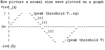
Its changing in voltage over time…What if, at the peaks the waveform had enough charge to interact with any other charged moment of a waveform.. ie.. for that millisecond or two, while the waveform isnear peak charge.. it would repel a like charge.. attract an unlike one.. and we, observing it, would call it matter… a particle.. having the properties of “solidity”
Then, as that point on the wave form drops below the threshold voltage necessary for charge interaction, it ceases to behave as “solid” and to our reasoning has disappeared.. well to my thinking nothing has to go anywhere… it was only the wave appearing solid anyway… the reality was the wave all along… NOT the particle.. being but a transient phenomenon due to the interaction of electrical forces.
The reality.. the wave.. is still there! In existence!
No other dimension… no leaving existence… the wave still exists… just not exhibiting the properties you observed a moment ago… : )
In other words.. the observed portion (maybe Domain?) of waveform at peak negative voltage (b), would exhibit the properties of an Electron… repelling other high enough negative charges.. and the portion at peak positive voltage,(a), would be a proton.. (positively charged “particle”)
The portion of waveform falling inside those two extremes (c) would be relatively NEUTRAL…Does this allow for electrons, protons and neutrons?
I then began to wonder about the possibilities of standing waves… agglomerations of countless waveforms… entrainment.. the fact that the portions of the wave acting as particles will have mass/gravitational properties…
I even threw in the possible part consciousness might play in generating such waveforms… a whole nother area which i couldn’t do justice to Scientifically… but which is very interesting from the point of view of healing and personal awareness! : )
Now if that doesnt give a skeptic something to attack my credibility with , nothing will… AS for credibility… I have only that afforded by dint of being human….
# Make a Radiant Energy Machine, From BNE http://www.byronnewenergy.com/wiki/index.php/Make_a_Radiant_Energy_Machine
(Original article by Sol Millin, BNE coordinator, Byron Bay, Australia)
I don’t know about you, but I’ve spent many many hours researching Tesla, Moray, Gray, Bedini, Testatika and others who have made amazing claims about a ‘new’ type of cold electricity called ‘radiant’ electricity. And after all this research, I had basically no idea what they were talking about or how to build a radiant energy machine.
Tesla claimed he could power our complete planet and all of it’s people, change the weather, bring rain to deserts with this power source. Tesla filed many patents but I’ve so far found them hard to understand, and nowhere could I find a definition of Tesla’s longtitudinal radiant waves.
Gray claimed he had invented an over unity (OU) device that could power homes, cars, boats and so on from two 12 volt batteries that would never run out of charge!
The Testatika site has videos of their strange looking contraption (looks like the Time Machine from the HG Wells inspired movie) lighting up 1000 watt globes from static electricity obtained from the air (via an inbuilt Whimshearst type static electricity generator).
Recently a member in BNE posted an email stating they are forming a group in Melbourne to research Radiant energy, and I found this email most readable. Here is the interesting part: ‘
Two great Tesla references “The free energy secrets of cold electricity” Peter Lindemann DSc http://www.free-energy.cc/index.html includes companion video and explains Edwin Grays circuit with respect to Tesla. That is the key reference for me but doesnt really go into the scalar waves. Tom Bearden does . My understanding was that Tesla was using a scalar wave technology as the carrier to raise the potential of the Earth (ground) as being infinitely more efficient (less losses) than trying to raise the potential of the ionisphere (great losses through air). This was his ultimate plan, to treat the earth to ionishere system as the giant capacitor it is.. then people would be able to tap into it at any point on the globe. I personally am not interested in powering up the world from a centralised local I think we have enough control issues on the planet already, so scalar technology hasnt come up for me yet. By following Tesla.. then Gray ..you will see the possibility of a home based power unit is within reach of the persistent researcher.
Gary Magratten has reproduced the radiant event by following the book then went secret to try and get bucks out of it… when will they ever learn! I think you ll be impressed by Peters lecture video he’s a good man well respected by many researchers. He also suggests ” Secrets of the cold war technology” By Gerry Vassilatos as essential reading… I havent got there yet. Thats all for now.
Happy researching Paul’
Thereafter I got hold of this fantastic DVD ‘The Free Energy Secrets of Cold Electricity’ distributed by Clear Tech http://www.free-energy.cc/ . In watching this DVD it is the first time I have understood what Telsa is talking about with ‘radiant energy’ and ‘longitudinal waves’ and Dr Peter Lindemann explains clearly how ‘radiant energy’ is produced, across the various researchers machines, comparing them and pointing out similarities.
I feel now that I’m almost to the point of being able to build a radiant energy generator which I am going to do.
As I proceed with this project, I will post designs and experimental data found. Within 6 months I hope I will be able to give you complete plans on how to build your own potentially OU radiant electricity generator. Lets start by discussing the radiant energy engine. This apparently is the creation of a very sudden and frequent interruption to a dc voltage. Various dc voltage sources and voltage interruption devices have been used by researchers. Apparently, if you interrupt the dc voltage within 100 microseconds or less, and do it more than 10,000 times a second you have a potential radiant energy engine. Now 100 microseconds is a time interval of 1/10,000th of a second which with current electronic circuit design is considered trivial to produce. Using the most common oscillator chip in the world the NE555 this can be achieved easily.
Later in this article we will give you a simple circuit which will output a variable frequency dc 12 volt square wave between 1kHz and 40kHz for your experimentation. You can use this wave form to drive your radiant energy engine through a simple Mosfet circuit which allows this wave form to be delivered at a very high amperage (up to 20 amps). The output wave form can be designed to be ON for a very very short period of time, thus consuming very little current in the primary circuit. Back emf from the primary circuit and some of the radiant energy from the secondary circuit can be used to charge a potential source (eg. 12 volt battery) which can alternate with the primary current source (another 12 volt battery) to hopefully produce an OU (over unity) radiant energy machine.
What we have to do then apparently is raise the primary voltage to some thousands of volts and apply this clean cut off (with no back emf) to our radiant energy transceiver which apparently creates a disturbance in quantum wave structure of Space itself that creates electrons in the output (transmitter) aspect of the radiant energy transceiver. The input and output circuits of the transceiver are electrically isolated from each other. The load of the radiant energy machine is run off of the output of the radiant transmitter.
So the potential interruptions in the primary circuit which by the way use very very little current, create the radiant energy in the secondary circuit which supplies energy to the load.
# OS:Ambient Energy Collection Device, From PESWiki http://peswiki.com/index.php/OS:Ambient_Energy_Collection_Device
Byron New Energy participant posts a method for harnessing radio frequency energy. The eventual objective would be to discriminate ambient space energy versus man-made radio waves, and to adequately amplify the energy to useful levels.
Here’s a project sent in by one of our members. It’s amazingly simple.
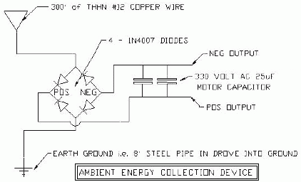
Make a 300′ antenna constructed out of THHN #12 wire about 14′ above the ground. Connect one end of this feed of the Antenna down into a four 1N4007 diodes and built a full wave recitifier. (see circuit diagram http://www.byronnewenergy.com/uploads/AECDSCHEMATIC.doc below). Connect up the antenna feed to the a/c side of the rectifier and the an Earth ground (15′ horizontal pipe buried 6′) to the other side of the AC input of the recifier. On the dc side (Pos & Neg) of the recifier, connect up to 2, 330 volt, 25uF, AC capacitors (Can type). Check the a/c voltage on the antenna antenna which should be in the region of a standing voltage of 20 – 21 volts a/c continually.
You should be able to continually collect or charge the capacitors to the standing voltage and above i.e. 300 volts. (see movie http://www.freeenergynews.com/Directory/Radio/AmbientEnergy.wmv ]) (youtube: ambient energy collection device http://youtube.com/watch?v=5mpYl3Yk8a8 .
You should be able to discharge the capacitors, displaying quite an arc, so the current level is high. The key to this circuit is the full wave bridge and not to large capacitors.
Apparently, this one works every time, provided one has a voltage on the antenna. Wow! How simple is this!
Further experimentation may be to coil the wire to make it more practical and also place it higher off of the ground.
Voltage picture
Schematic
Further
Ok, the 300′ of #12 THHN is what I had around, so use I it. I had tried #16 and it worked from a while but broke in two in time. The #12 has worked out very well due to the weather we have here i.e. Snow, high wind at time, etc. Also the larger diameter helped with the standing voltage on the antenna (20 volts AC).
I do not feel that the device is receiving static charge, but RF (radio frequency) energy. Also as far as power I have been able to draw a 1/4″ – 3/8″ arc when shorting the caps. There is power in the current setup, but really needs additional work to improve it.
One option I am going to try is to make a air coil out of the wire and elevate it 20′ – 30′ . If i did the math correctly the coil antenna should be about 6′ in length. Planned on using 4″ diameter PVC pipe to wrap the coil on. Picture a T section with 3′ of pipe on each side of the T. The long leg of the T would be the mast. The mast was also going to be made out of the same stock. The larger section of the mast will allow for more stability. Another option is that this concept could be rotated for tuning purposes.