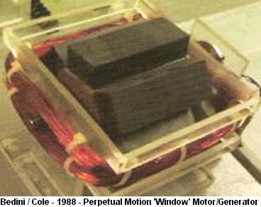
The WINDOW MOTORs by John Bedini and Rone Cole, 1988:
20 Bedini-Bearden Years ‘Free Energy Generation’
Extracts from http://www.icehouse.net/john34/bedinibearden.html
Special thanks to all the groups who kept the faith.
Window Motor, Bedini/Cole This motor has been on the same batteries for over 15 years.
– video at http://www.icehouse.net/john34/Window.wmv
The Bedini/Cole “Window” Motor, from Patric Kelly pdf file ‘D3’
http://panacea-bocaf.org/files/patrickkelly/D3.pdf
In September 1988, Jhon Bedini and Rone Cole produced a very interesting motor. This motor does not produce any great output power as it spins, and yet it is an important device because it can run indefinitely without needing a battery to power it. Instead of a battery, the motor uses a capacitor. Initially, the capacitor is discharged fully, showing that the device is definitely at a minimum power level. The motor is then given a gentle spin, from which it develops its own power and accelerates to its normal operating speed. The fact that it accelerates from the initial spin rate, demonstrates that the power is not coming from the starting energy.
This device is a perpetual-motion machine, and that is a major problem for conventional science of today, which fondly imagines that perpetual motion is impossible. No calculations with their assumptions and possibilities for error, are needed for this motor. There is no external input power, and yet the device produces motion, sound, heat, mechanical wear and in addition, it generates increasing charge on the capacitor. That charge could be taken off to charge a battery, but this is not done so that there is no possibility of people thinking that the battery being charged is actually powering the device.
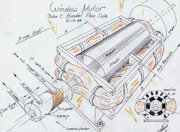
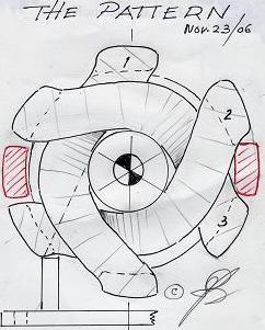
This is the drawing produceed by John and Rone in 1988:
And a circuit drawing:
In this circuit drawing, the option is given for either battery charging or operating from a capacitor. We are interested primarily in the capacitor version as it demonstrates very clearly that conventional science needs to be revised to encompass both perpetual motion and the Zero-Point Energy field which provides the power for what we see as perpetual motion:
Several variations for this design are possible. John shows the timing for the pulses taken directly from a commutator where sliding contacts move across a copper strip on the shaft of the motor. The version shown in the video of this motor running, uses a Hall-effect semiconductor to sense the position of the shaft magnetically and utilises solid-state relays to do the switching.
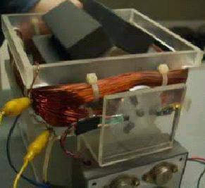
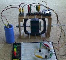
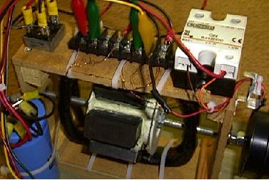
The original construction of the motor is shown here
and you can see that six bare magnets have been attached to a central hexagonal former surrounding the central shaft. Very simple construction. The bi-filar coil is wound with thin wire being used for the signal drive to the MPS8099 timing transistor. I understand that this motor is to be shown in the new Bearden/Bedini instructional DVD soon to be released via http://www.energyfromthevacuum.com/Dics2.htm being the second DVD in the series.
I have no hesitation in recommending the first DVD ‘Energy from the Vacuum – Disc 1’ which explains clearly how an energy flow from the Zero Poit Energy Field is generated, amplified and converted to conventional electricity. It also provides considerable information on the ‘Motionless Electric Generator’ (the MEG of Tom Bearden) and its technique for getting greater power output than the input power.
Fom pdf file: Window Motor (A-field) Notes, Compiled by slloyd
Nov 26 2006 ; pictures with video http://www.scene.org/~esa/merlib/bedinicole/bedinicolepack1.zip
The following comments are with regards to the movie “bedinicolemotor.mpg”
Bedini Cole Window Motor
Sun Nov 19, 2006 3:11 pm, Message #3787 of 3797
To All,
If it’s ok with Rick I will post all Ron Coles Drawings, I don’t know much space is here. But if we do not have the space I will make an internet page. As to the drawing on my lab note I think you understand where the energy comes from.
This takes time to see this in your mind, once you understand you can make any motor do this. Take the window motor wind it like the SG when you connect it like the SG you will have better performance, since there is no iron you can use neo magnets, when you see Ron Coles drawings you will understand how to make three window coils.
The impedance of this motor is very low, you want to start with a moderate impedance at first, say 400 turns around the outside bi-filer. Later use Cole’s circuits, if you get the hall trigger right you can hook a big capacitor to the diode bridge and the motor will run itself for some time, but we will get into that later, one step at a time.
Ron Cole was a Newman follower he tried to show Newman some things but Newman went nut’s on him.
What you will learn is that you can make this device many ways, with many different circuits. I will only post this one time then I will take the page down after Rick gets all the information for the group.
Tom Bearden and I have decided to give as much as possible at this time, so I’m only going to give this to trusted groups. Sterling and Eric K , they are doing everything possible to stop the book from coming out, I have seen the E-mails to Tom, and his crappie analysis of the SG project. His own data proves that he did get it to work as I said to him in the beginning.
John
# Message #3794 of 3816, Tue Nov 21, 2006 2:28 pm
The next video I put up here will show the Cole Motor running on it’s own energy, I will be the one doing the hook up.
The monopole experiment was to get you to understand the important part of hidden magnetic fields and switching, the switching is the important part.
Without the correct switching you will never make it happen, you are a smart group and should figure this out right away.
Be very careful they will come after you if you talk. Hide your machine in your mind and wait for the right time. When God says go I go, you should do the same.
Message #3814 of 3817, Wed Nov 22, 2006
1:03 pm NOTE: Some {comments} are by slloyd
Re: SWITCHING – TESLA MAGNETO VERSUS OPEN A-MOTORS
Mr. Hurst,
We have found the window motor {bedini cole motor} to be the most efficient. The switching is exactly like I posted in the photo album section {provided below}.
You could change the Monopole to do the same thing but this would take much work.
The Group wants a self runner with extra power output, so I posted everything Cole and I did to get everybody to understand how simple this can be done. Example the Sweet device crossed coils, generator, motor coils. The charging of the capacitor and switching is the critical part.
The motor I show { bedinicolemotor.mpg } is just a prototype to do the experiment, The extra coil you see on that motor {now sure which motor he is referring to} is so I can run this using the monopole circuit. Rick’s video {Window.wmv} shows where the generator coil goes, indicated by the flashing lights.
The reason I told the Lockridge story was to get everybody to understand the two independent coils, one set charges the capacitor the other is a motor, one fired single pulse saving the extra pole (South) in the rotor for the generator. The capacitor must be chosen for the correct value to gain energy as fast as possible as a normal generator using a full wave bridge rectifier.
You do not want to waste power in the motor function, MASS weight is important here for rotation. The Bi-polar switching allows for this to work with one power coil with the bridge connected across the motor coil as shown in the video.
The switching time for the Bi-polar switch must be very short in the switched ON time, where the monopole switch is self regulating with the trigger circuit wound with the motor coil, give’s one sharp pulse to the motor.
What we are looking for is to self run the motor, and pull extra energy from the AC part of the generator to run lights or charge batteries, keeping the capacitor charged to run the motor.
John
Message #3839 of 3847, Fri Nov 24, 2006 10:39 pm
Re: Rick’s Window Motor Movie – comments & discussion:
– On Para 2.g. below, yes, I concur with your notes. Here is the real kicker. Everyone please read this slowly and carefully. When Mr. Bedini hand-spins his 6 pole armature, at first, the cap is empty (we can safely assume this). After running it a few times, he stops the armature with his hand. The armature restarts rotation without any intervention. This indicates there was A NET GAIN from start to end.
– Here are two very important observations:
1. The armature was spun by hand. It means the armature cannot have been spun to any high RPMs; it is physiologically impossible.
2. This means that UNLESS the hand spun RPM reached a speed above the motor’s normal steady-state RPM, (which would pump the cap with more energy than was being consumed by the propulsive pulses), it is this motor’s natural tendency to develop a surplus of energy in the capacitor.
– The implications are incredible. With a motor like this, using a heavy flywheel for conservation of as much angular momentum as possible, it should be possible to periodically dump that capacitor to a battery or load a supercapacitor, which gives us a a NET GAIN in usable DC electrical energy. Imagine what one might do if you had an outboard motor pull cord on that shaft to really get that thing whizzing at the start.
– Carl, this is the motor they stole from my shop, they did not get this one or the model because they were hidden away, I’m dead serious when I warn you all about what happened. once again this motor needs the sharpest trigger you can give it. “General Electric took Ron’s Motor” , one thing you will find out about me is I do not kidd around when I show you something, I could have took Sterlings buddy’s money, but then where would Eric K be, he would then maybe jump of a bridge somewhere
– (As an aside, I bet this kind of motor would run very well with a rotating spark gap commutator in place of the circuits and hall switches. A kind of Gray Window Motor which runs on nearly pure potential and almost no current…)
– You are correct again. Carl you think I should find a dead battery to run it on and film it, think I will.
Build it Carl, Build it, you can see it in your mind.
John
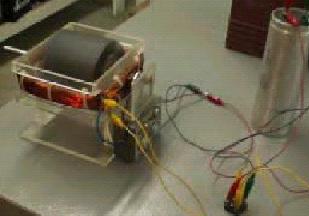
The following comments are with regards to the movie “Window.wmv”
Movie downloaded November 22 2006 from, http://rpmgt.org/Window.wmv
# Message #3810 of 3817, Wed Nov 22, 2006 2:01 am
Luther,
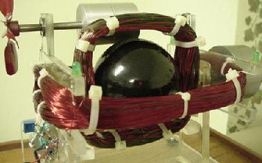
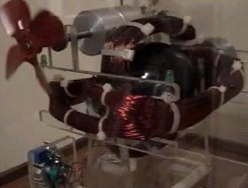
The ball in the center is the motor, the fields are so strong from the neos that they make the aluminum wheels turn to form a transmission. If you move the fan alignment the fan will go through speed changes. This is a all in one machine.
Built in 1987. John
# Message #3820 of 3821, Thu Nov 23, 2006 3:38 am
Re: Rick’s Window Motor Movie – comments & discussion
Correct you did here me say I wish I had more weight, I just could not find the extra flywheel.
The Fan, The fan is connected though that long shaft. the shaft has two aluminum wheels the neo magnets create an eddie current in the wheels, this turns the fan. Notice that the fan bearings are in slotted groves if you angle the shaft the magnetic spins angle different causing the fan to slow down, if you angel the other direction the fan speeds up. It’s like having a cone drive transmission, no effect on rotating mass.
The ball is from a planetary machine, it’s machined, boring 1″ hole through the ball. Inside the ball is a steel slug on top of the slug is one 1″ neo magnet north and one south on the other slug, now you have a ball with a north and a south. The shaft is through the center on bearings. At the back of the shaft is a mass weight 1lb flywheel for rotation.
The circuit powering this is the monopole circuit one pulse at a time. The coil that is horizontal, is the generator coil for the capicator, led’s are just indactors for the north and south poles passing.
This is a straight Bedini/Cole motor, monopole switching. It’s just a model so I would never forget what I learned. The real machine was dismantled when Cole died, I’m giving people, in the book, the 1971 lab notes of all the different monopoles I built, about another 40 pages in experiments.
The rest you will find in the dump one day. John
From Bedini’s ‘old website’
http://www.icehouse.net/john34/motor.html
Modified Bedini Cole Window Motor
http://peswiki.com/index.php/OS:Modified_Bedini_Cole_Window_Motor
Mike (HMM) from the gn0sis http://www.gn0sis.com/ forum has built a modified Bedini Cole window motor which he can run without batteries for hours and can charge up empty capacitors. The motor does not run indefinitely. The thought is that it might be made to with more robust components. During the one time Mike’s unit was allowed to run overnight, it fried components in the circuit, presumably the capacitor.
– Although Mike will not make the claim, as he has not made detailed measurements, a motor that runs for hours without any battery input only a starting twist of the finger, and revs up to find it’s own level, even after discharging the cap, would seem to be.
– Feb. 14, 2007 ; Mike’s success announced by Stefan Hartmann at OverUnity.com [4] http://www.overunity.com/index.php/topic,1988.0.html
– http://www.fight-4-truth.com/Schematics.html – Mike says: “This link is very good. I learned alot from these illustrations, look at the commutator to see the timing …”
– Files : For the sake of brevity, a package has been made with quite a few pictures and the video related to this:
# pictures with video http://www.scene.org/~esa/merlib/bedinicole/bedinicolepack1.zip
# pictureswithout video http://www.scene.org/~esa/merlib/bedinicole/bedinicolepack1withoutvideo.zip
# Bedini/Cole window motor movies and discussion from 2006 http://www.scene.org/~esa/merlib/bedinicole/Bedini_Cole_window_motor_movies_and_discussion.pdf , file referenced here : http://tech.groups.yahoo.com/group/Bedini_Window_Energizer/message/15
# Bedini/Cole Lab notes http://www.scene.org/~esa/merlib/bedinicole/bedinicolelabnotes/ (mirrored from BediniWindowEnergizer-list)
– Rebuttal : “I don’t think he considers the fact that it runs for several hours while overcoming air resistance, bearing friction, [while charging] a cap upwards. He only thinks it’s not OU because when he tries to load it down, it stops; and because he cannot power a large external load. He has not considered all the factors!” — David Clarke ( davidclarke@ctglabs.com ) (02/15/07)
– Note : Mike says it does not run forever. This is correct, but it should be noted that when the motor stops it’s because it has burned out parts of it’s circuitry. So far it has only stopped because of component voltage ratings were not high enough to handle the current generated by the device. It has never spun down to a dead stop.
– Math Does Not Point to Overunity Here , On Feb. 16, 2007, New Energy Congress member, Robert Indech , PhD PE wrote:
The motor design presented is interesting, but, as its inventor claims, it is not over-unity. One piece of major evidence of its prowess is its ability to charge a 47,000uF capacitor to 6 volts with hardly any change in its rotation rate. Let us consider some of the physics of this design, particularly a calculation of the energy required to charge the capacitor, and a rough estimation of the rotational energy of this motor. Since neither materials, not dimensions, are presented on the website, I am only making a rough approximation for the latter based upon what I can estimate from the images.
The energy to charge the capacitor is E= .5*C*V^2, or inserting values: E= .5* (0.047)*6^2= .85 joules.
The rotational energy of the motor is calculated at .5*I*w^2 where I is the moment of inertia of the rotating cylinder and w is the angular velocity. Suppose that the motor rotates at 3000 rpm, which is 50 revolutions per second. The angular velocity is then 50*2*3.14 =314 rads/sec. The moment of inertia of a solid cylinder is given as I = .5*m*R^2 where m is the mass and R is the radius. Since I do not know the exact composition of the cylinder, it looking like a composite of metal and plastic, I approximate the density, “dn”, at about 5000 kg/m^3 (compared to steel density at 7850 kg/m^3 and water density at about 2260 kg/m^3). I would figure that the diameter of the cylinder is about 3 inches (or 0.076 meter) and its length is 4 inches (or 0.1 meter). From this approximation, its mass would be calculated at m=3.14*R^2*L*dn = 3.14* (0.038^2)*0.1*5000= 2.3 kg. The moment of inertia would then be I= .5*2.3*(0.038^2)= 0.0017 kg-m^2. The rotational kinetic energy would then be: E= .5*0.0017*(314^2)= 83.8 joules.
From this rough analysis, it is seen that the rotational kinetic energy is approximately 100 times that of the capacitor charging energy. Thus, one would expect hardly any change in the apparent rotation rate of the armature due to the energy draw to the capacitor.
– Response by Dipl. Ing. Stefan Hartmann (Feb. 16, 2007) : [It seems that] Robert Indech did not look very closely at this video.
1. The extracted energy of about 1 Joule = 1 Watt-seconds is about right. (it is almost 7 Volts not 6 Volts)
2. But when you look closely, you can see that Mike is just tipping the rotor at the start, and gives it a light spin; and it actually increases its speed during the charging at least 2 or 3 times; and at the beginning it is probably only 5 rev/second so 300 RPM.
So it is a factor 10 less input energy already as Mr. Indeech calculated, and also its mass is probably much less than the guessed 2.3 Kg — as you can see how easily it is turned back and forth! A 2.3 Kg mass would not be so easy to spin up back and forth, as it would have much more inertia… ! So I guess the mass of the rotor is at maximum 500 grams or less…
So already the fact that the rotor accelerates in RPM while charging a cap and the motor runs for hours and hours while not slowing down, while charging the cap higher and higher indeed [indicates] overunity.
– On Feb. 16, 2007, New Energy Congress member, Ken Rauen wrote:
This is the best video documentation http://www.zpenergy.com/downloads/winmotor.wmv of an invention I have seen yet!
For the first time, from such evidence, I believe there is something there, assuming the small details I cannot see are not energy sources. I believe so because
1) the rotor is started by hand at slow speed and accelerates, as evidenced by the “picket fence” effect with the video frame rate, AND
2) the voltage of the capacitor climbs! There is no way the hand twist start imparted any energy that was stored and released slowly to accelerate the rotor!
Robert’s energy calculations make it all the more impressive, as capacitor relaxation (from incomplete discharge, even though the meter showed 0.0 V briefly) could not have provided the acceleration energy, for the rotor at full speed had 100 times the energy of a fully charged cap.This seems to be a 1/4-hampster-power demonstration!
– Bedini comments on Gn0sis , On Feb. 17, 2007, John Bedini wrote: Mike,
This is great work, It seems you have created a great debate in the energy community, that’s good they need it.
As stated these drawings and machines have been on my internet sight since the internet started. I’m not here to find fault in anything you have done. I’m going to point out that unless everybody in this group follows your variation to the T “They are doomed to failure”, In replicating your motor.
The Window Motor is very close to the many I have built over the years, however unless everybody has your exact details, wire size, lengths in feet, switching devices, exact circuit wiring and so on, they will never reproduce it. The first thing to state here is that their is a big difference between efficiency and COP of the system. In the motor you reproduced your efficiency is around 99.9 but the COP is over 100% that is why the “CAP charges” up. The next problem is that your hall device can not work correct, because of the Radiant spike, if you walk away the Hall will soon burn out and that part will hinder your performance.
So I will state for the record right here the Motor section is not over unity and your statement is correct. The Group needs to understand what they are building, they are building a machine that takes advantage of a simple trigger system, you must supply the trigger to cause the effect to happen. It is that trigger that causes things to happen, it’s known as a sharp gradient. Sharp gradients cause normal EM systems to do real funny things since it is not in the normal text. For example the correct sharp pulse can trigger a battery to recharge itself, it can cause a capacitor to recharge itself and so on.
You are dealing with quantum systems when you cause this to happen, and they look totally different from the standard EM systems, when you combine the two you have real trouble. Normal EM systems are designed to never be over unity and you only have meters and scopes that see only this, you can not see in the Quantum level with your instruments.
The original Maxwell equations allow the production of The term FREE ENERGY, the paper is on the internet and also it can be found on Tom Bearden’s Internet Sight. I’m Not here to have a debate with any people that think they know better, I do not want to discuss the TURBO CHARGER, which was mine in the beginning, I do not want to discuss Glow bulbs, or I think that this is what is going on, because it’s not what is going on. You Have made a great leap in what you did and posted to the internet in this group along with the Video.
John Bedini
– 2007/02/19 17:01
One thing to remember here is that The Bedini Cole switching circuit allows the supply to be independent from the drive coil. Cole and I have made Power Amplifiers using this circuit forever, Alexander has nothing to do with this motor concept as it does not use the same switching. I have posted, and commented on this machine.
Mike used the very first switching circuit we developed to switch a two pole motor. The bipolar switch uses hall’s but halls draw current which drains the capacitor. So you must be very clever in how you switch this motor, I said that you must switch only one time, that means one powerful motor pulse. the rest is a generator action to charge the capacitor to the voltage level the motor will seek, get it.
After that the motor will fight all the known laws affecting motors, standard physics. You must be smart enough to trick this pass the known laws. I will find the 1st drawing and post it today.
John Bedini
compilation of bedini comments, some which arent on this list http://tech.groups.yahoo.com/group/Bedini_Window_Energizer/message/1
From the VERY DETAILLED and CLEAR website of Erwin
about his Bedini’s replications http://www.fight-4-truth.com/Schematics.html
… When you build your first window motor use a steel shaft through an armature core of 2″ hexagon steel 5″ long (unless you have an extra long 7/16 and 1/2″ drill bit) and 1x1x1 neo magnets with three coils complete using 2-UGN3020T’s Hall preferable for the switching. The perm. setting of the N and SHall are at 180 ºopposing each other, whereas the three magnets on the little disc are on a 120º spacing, giving you a total maximum “off” period of 90º or25%. Hence it is evident that you have to switch both the N and the S. Use the Cole Bipolar schematic for now with two power silicone transistor MJE3055, NPN, two MJE2955T, PNP,10A, 60Vand two MPS8599 amplifier transistors (PNP’s). This is enough info to make it work. Perhaps later on I will be able to show you the full Cole-Bedini Motor schematic and more of John’s drawings. Wind your first three coils bi- or quad-filer #18/23AWG or quint-filer #23AWG, image 13, that way you are not committed to hall switching. Twisted wire gives you more voltage also the coils end up deeper, hold the wires of the coil together with lacquer and cloth or super glue in spots(it has to be slightly flexible) as one unit before you take it out of the jig (wax the jig).
If you switch it properly you can make it run itself. Don’t give up if it does not work the first time. Use pots on all the resister and keep working it. Use a big capacitor and let the motor charge the capacitor while you spin it, by tapping eithercoil for the AC, incl. the red one, at different times over a full wave bridge rectifier (FWBR) to the capacitor with the running leads of the motor also hooked to the capacitor……
Yes, there is two ways of self running this motor. The easier one is the 1st. With commutator switching from the energizer back and forthbetween battery and motor. Keep in mind that you can’t charge a battery while extracting energy from it at the same time without destroying it like they do in cars.
2nd. Tapping AC from one or more coils via FWBR directly into a big capacitor while running the motor from that capacitor. — If you are wise, then you know how you have to handle this new gained knowledge!! Ron Cole apparently wasn’t …….
Make sure you keep an eye on the written text, all you need to know to make it work, you’ll find right here in my pages. If you think not, then by John’s book! The motor won’t likely run itself unless you construct it as show on this pages. For the last 7 years no one has publicly shown Bedini replication success (with God’s help) as I have within this two last years.
No relay is needed to run this Winow Motor!!! Had you known mypage content, you would also have had your doubts about mikes motor!
… Work it until you have it. I can guarantee you that it works. I am not going to prove anything by video. John did it, which should be good enough for anybody and enough incentive to get going on it and build your own. Don’t forget the big wheel for kinetic energy to give the motor momentum, the bigger the radius of it the better. If you can install a pulley to pull start the motor (rob one out of an old lawn mower or read “Cone start” under start up), to pressure up that cap quickly, you’ll have instant Volt-torque for RPM acceleration. John Bedini demonstrated the motor with one coil to us through a video by just rotating the rotor by hand and said: “I would really like to have a mass, like the other, but I don’t have it”.
… Make sure the magnetic poles are N and S in line, the N-pole is switched on the N-pole side of the “A” field of the coil while the S-pole is also switched on the opposite “A” side of the same coil in intervals. Itis entirely possible that the coils which are setup “in phase” are in charging mode on one capacitor while a second coil marked in red “out of phase” is running the motor from another capacitor!!! Perhaps the second cap could be pressured up and then dumped into the first cap. I am far from an E. engineer, but flexible thinking helps :). Through trial and error I willget to where I am headed, so be patient with me when you see blunders I am making. I’ll fix them as I see them.
The commutator in image 15 above, which is my design, is a mechanical switch, it works with HV if you can keep the brushes from burning up at high voltage. The SSG or window motor is just a mechanical way of triggering this radiant energy and the copper wire is the collector of it, and it closes the loop to charge the battery. I built the commutator or better on-off-switch in a similar way as I pour my little rotors/spools. I’ll have a write up in my work shop later on some times. I used two sizes of copper pipe. One I cut in an angle clear across, the other bigger one I silver soldered the inside “ID” and machined it out to the same OD as the commutator and cut it into segments for the brushes.
You need to use two 1/4 NC set screws in the epoxy from both sides, that way you don’t have to tighten them too much. Don’t use more than 10% talcum powder or none at all in the resin in this case depending on size, just cool it in cold water while it is hardening if you can’t touch it anymore. If you strip the threads, drill it up to 1/2NC, pour the bore with straight resin again and re-cut the 1/4 NC thread, it’s easy, it cuts like cheese :).
Cole-Bedini Motor update
Be aware that this Motor can be setup and switched in a number of different ways. Also be aware that we have been riped off by the elite cartel right to the very basics in how to run a generator. If a certain generator is set up with “two more coils” 90º apart with a capacitor the generator can be operated as a motor/generator running itself after it has been started with a pull cord!!! Remember that I titled my website “fight-4-truth”!
… To All,
During world war two, two GI’s wandered into a little town in Germany.The Two Gi’s were shown a BOSH generator that was modified; they crated it up and sent it home. The device used a pull cord to startit, once it was started it ran itself at 5000 rpm’s and lit 300 wattsworth of lights, any more it would quit.
The secret to the machine was switching and a special capacitor made from waxed butcher paper.Without the capacitor it could not transform the spike from the motor. It was called the Lockridge device, he built this with DelcoGenerators that he took apart and modified by adding “Two more coils”90 degrees apart”.. The switching, When the machine quit running the brushes failed, people would go to the auto parts store and buy brushes install them and the machine would not work. Lockridge did not tell them that he sanded the brushes smaller than the commutator segments, so the people sold them for the copper.
Lockridge was hunted down by the department of energy and they could not get him for anything, so they worked on his wife who became the townH….. , Lockridge went nuts and poured gasoline on himself and lit the match. The machine was never seen again. I know about this machine because of a good friend who talked to people that owned them. This was a real machine that ran itself closed looped, the Cole/Bedini motor can do the same thing without the brushes.
The switching must be right along with the generated output. We have all the bestmagnets today to do this.
Also consult: http://www.icestuff.com/~energy21/bedmot.htm