### Mc Kay investigate Edwin Gray’s story, page 2: (page created for November 2007)
For more info on Sparking, see also
– HV Marx Generators zpe_marx_generator.html,
– Spark Gaps zpe_sparkgap.html
– Sparking Experiments by W. Alek zpe_alek.html
## Part 3: Secrets of the EMA4 and EMA5 Control Commutators (Still Unresolved), Mark McKay,, ‘McKay3.pdf’, 6 pages, 271kb, from files of the YahooGroup ‘alfenergy’
While the technical revelatins provided by the disassembly of Mr. Gray’s custom electromagnets is important, the observations collected from the EMA4 and EMA5 control commutators are even more interesting (and perplexing).
Prior to the recovery of the EMA4 and EMA5 it was thought that the attached white cylindrical device on the back of the EMA6 was a simple rotary positional timing commutator device. According to patent 4,595,975 a commutator like device was included in the schematic diagram. It appeared to be some kind of mechanical rotary switch that controls timed pulses of power to flow through the anodes of the CSET. So when the patent and the photos are examined together the arrangement seems plausible.
See comparative pictures on original document
As it turns out the EMA4 and EMA5 motors reveled a much more complex component for researchers to consider. These commutators were constructed in such a way that they contained way more contacts than what would be needed for simple positional feedback. The units that came with each motor were designed to be pretty much the same, however they were wired differently. More control wires were utilized with the EMA5 than with the EMA4. This would be consistent with the fact the EMA4 only had one electromagnet pair to pulse while the EMA5 had three. The EMA5 commutator used 9 of its 15 contacts and was connected with 7 control wires. The EMA4 commutator also used 9 of its contacts but was only connected with 3 control wires.
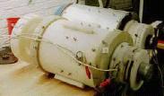
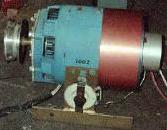
EMA4 and EMA5 Motors at the time of recovery in 2000.
With external Control Commutators mounted on the right
An examnation for wear on the commutator contact surfaces, from possible arcing and heating, showed almost no signs of degradation. The conclusion reached from this observation was that wathever energy passed through these devices must have been at a very low level. This being at least two or three orders of magnitude less than what would be needed to pulse all the stator and rotor coils at once. Estimated classical current levels of less than 1mA at 200 Volts have been proposed as being an upper limit. Mr. Wooten examined these motors from a mechanical point of view, using his professional expertise, and reported that each motor appeared to have logged at least several hundreds hours of operation. Yet, you would never conclude that much use by looking at the contact surface alone. It is possible that the commutators may have been replaced, prior to being taken out of service, but that is a long shot.

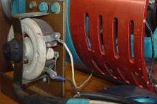
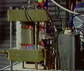
Norman Wooten displaying the Non-Disclosed Complexities of the Timing Commutator from the EMA5
Gray motor at the 2001 Keelynet Conference – Courtesy Dr. Peter Lindemann.
Observing the lack of wear, the new belief is that the commutators were providing both control timing and positional signals to Mr Gray’s energy converter. They were defiantly not directly switching the prime power that went to the stator and rotor coils. Further more, these timing signals were more complex than even thought. In the recovered motors the commutator section and the motor electromagnets were wired independently.
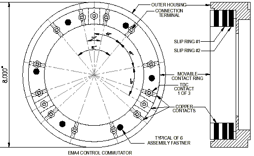
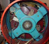
There are 15 contacts and two independent aluminum slip rings in each commutator subassembly. Three of these contacts are rectangular (1/4″ x 3/4″) copper bars that are three times wider than the remaining 1/4″ diameter copper rod contacts. For both motors there appears to be two general timing patterns that emerge when looking at the angular spacing relationships of these contacts.
1) The three large rectangular contacts and 6 of the smaller contacts are equally spaced 40 degrees apart from each other around the circumference of the mounting ring. These would provide a continuous evenly spaced train set of short timing pulses, proportional to the speed of the motor, with every third pulse having three times the pulse width of the others. But, this is not what has been wired to go to the energy converter.
2) There is also a repeated pattern with three clustered contacts. This group is composed of two small and the one large contact. These seem to be related to the ‘firing’ of the electromagnets when the wiper is about 6 degrees past TDC.
See schematics on the original document.
The rotary aluminum shaft wiper houses a spring loaded metallic ‘brush’ that connects each contact to the slip ring in a sequential order. A second aluminum slip ring was installed, but was not utilized in the EMA4. If the slip ring were considered a circuit common then the timing pattern shown in Diagram 01 would be the result. Again not all of the contacts were used in either motor. This is indeed puzzling. Apparently different circuit configurations were being planned that might have used all these contacts.
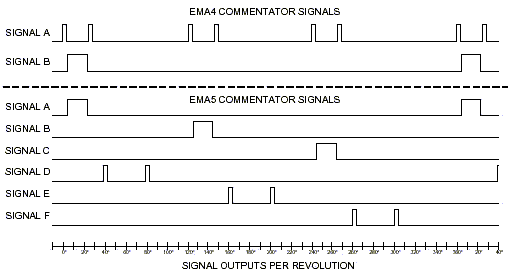
Timing Diagram 01 for Control Commutators for the EMA4 and EMA5 EV Gray Motors
Mr. Gray used a construction technique that is not generally seen in rotary equipment. There are three slip ring assemblies used in each of these two motors. One assembly is used in the commutator subassembly and has two slip rings sharing a common wiper. The other two slip ring assemblies are used to conduct pulse power through the rotor electromagnets. One is in front and the other is in the back of the motor. All three of these slip rings assemblies have an uncommon internal design. This is because the wipper and ‘brush’ are rotating around the inside of a stationary slip ring. This is just the opposite to 98% of all other industrial machines in the world that use slip rings. Almost always, the slip rings are attached to the rotating shaft and the contacts or ‘brushes’ are stationary. The obvious advantage of this common approach is that it allows the brushes to be easily replaced when they wear down. Another important advantage is that the ‘brushes’ can easily accomodate some imperfections in the roudness of the slip rings that rub againsst them. This is because the brushes are mounted in spring loaded holders that allow them to move back and fourth. However, in Mr. Gray’s design, a brush or wiper replacement would require way more disassembly. Also, it doesn’t appear that this design could allow for nearly as much deviation from tolerance as the standard brush and slip ring arrangement can, We just don’t know what the application specific reason was that promoted this king of solution; it certainely is not obvious from looking at the notors alone. Mr’ Wooten contends that he could have designed a much better system to get the power into the rotor as well as several other major mechanical system improvements. So far no one has disputed his claim.
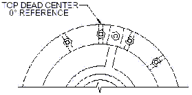
It is interesting to note that the Top Dead Center (TDC), the position where the electromagnets are squarely aligned with each other, takes place when the wiper is on the first small round contact in the cluster of three contacts, rather that the larger rectangular contact. Mr. Gray designated this location as 0 degree. It has been proposed that a certain amount of angular displacement is needed between opposing electromagnets when operating in the repulsion mode to insure that the generated forces are focused in one direction. Perhaps Mr. Gray determined that the optimum angle, for this size motor, is around 6 degrees. The actual working angular displacement could be adjusted. Perhaps this was just a convenient reference point and had nothing to do with the function of the motor.
According to the jacket information the control conductors leading off from the commutators are rated at 25kV. Yet, their overall diameter is equivalent to common #14 AWG THHN household wire (0.12″ diameter). This is much smaller than typical electronic high voltage wire that has this kind of voltage rating. This wire was probably an expensive specialty cable in its time.
The small spacing between the wiper and the contacts in the clusters of three suggests that Mr. Gray didn’t utilize any classical control voltages that had a differential greater than 200V. If classical electron flow were involved then voltages higher than this would have caused arcing at both the leading and trailing edges of the contacts as the wipper approached and receded from them. Again arcing was not observed. Then what was the purpose of the expensive high voltage cable ? One proposal is that all of the control voltages connected to the commutators were elevated to some high value and their differences was less than 200 Votls. This means that the whole commutator was ‘floating’ at some high potantial above ground. the overall nylon construction of the commentator assembly suggests that it could have easily have supported this kind of high voltage operation (5kV to 20kV). The commutators on the EMA4, EMA5 and EMA6 are all mounted almost independently and external from the motor proper. This construction feature might imply a need for a high degree of isolation between the motor and the commutator. If so, then it is a distinct possibility that the commutator did operate at some high floating voltage.
The purpose of the various timing signals has been discussed within the Free Energy Community but so far no general conclusions have been tendered that would explain how they affected the energy converter’s circuit operation.
It appears that the energy converter needed at least two date streams, only a portion of which was the simple positional information. The rest of these short contact closures are assumed to be signals that could prepare the enrgy converter for its next pulse or to, perhaps, facilitate some kind of energy recovery cycle. There are four contacts between each TDC position; therfore there are provisions for as many as four changes of state per each power pulse. Not all of them were used at the time these motors were taken out of service, but they could have been.
Mr. Wooten, in his 2001 video, claims that the commutator compartments were filled with ‘Luberplate’. This is the trade name for premium quality white lithium machine grease. Given that Mr. Gray didn’t seem to spare any expense in the construction of this subassembly, then what Norm could have observed might have been a special High Voltage Teflon/Silicon insulation compound that is used in the X-Ray business. This would have help to extend the voltage differential of Mr. Gray’s control signals to may be 500Volts or so. However smearing insulation grease (or any kind of grease) on moving electrical contacts is a risky business. This is because it is difficult to build a system that will reliably wipe all the grease off the contacts just prior to contact and still provide a consistent low resistance connection.
Both commutators were built so that the contacts are housed in a movable nylon ring. This ring was installed in a larger hollowed out cylinder that acted as a housing so that the whole collection of 15 contacts could be adjusted together in relation to the shaft position. A machine set screw allowed for a wide range ot timing angle adjustments (-40 to +40 degrees). At a setting of -16 degrees, according to notes written on the commutator, the pulse motor would run backwards. Probably not at full torque, but this shows that these motors were reversible.
After the recovery of the EMA4 and EMA5 motors the idea that Mr. Gray’s energy converters were dirt simple has come to be questioned. The revised thought is that the Mr. Ggray’s low energy technology may have been simple, but the higher power technology now appears to be more complex.
Photos of EMA4 and EMA5 motors are the courtesy of Mr. Norm Wooten via the KeelyNet.
## Part 4: Starting with the Start Motor, Mark McKay, PE, ‘McKay4.pdf’, 5pages, 987kb, from files of the YahooGroup ‘alfenergy’
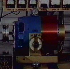
The Start Motor as found in 2000
E.V. Gray one commented to John Bedini that his early free energy experiments were conducted with modified off the shelf industrial motors. It is assumed that when Mr. Gray’s finally adequate funding he went on to build a series of custom made motors that could take better advantage of the unique properties of his non-classical ‘Cold Electrcity’. These experimental designs were stamped with the model numbers EMA1 through EMA6. The EMA4-E2 and the EMA6 are his most well known constructions and are always associated with Mr. Gray’s work. However, there were other transitional models built.
There may be one recovered example of a pre-EMA series motor that might have served as a functional test bed and very possibly an early investor demonstration model (circa 1963 to 1969).
In 2000 friends of Norm Wooten discovered two original EV Gray motors in a shop somewhere in Texas (most likely Grande Prairie, Texas where Mr. Gray had established a shop in 1986). These were the EMA4 and the EMA5 prototypes. Mr. Wooten acquired these pieces of history from the building land lord. He then took them to his shop where they were carefully disassembled. Later he produced a highly recommended video of his observations for the 2001 Keely conference in Florida. This informative tape is available from Clear-Tech at http://www.free-energy.cc in DVD and VHS formats. At the time the ‘Start Motor’ was considered insignificant and therefore not looked at very closely.
After considerable mechanical analysis of the EMA4 and EMA5, Mr. Wooten came to the conclusion that this equipment contained no obvious free energy secrets. The vital energy converters that had powered these unique motors were not found. A few years later he decided to sell this collection.
Mr. Allan Francoeur of Penticton, BC, a long time free energy researcher and inventor, bought the entire lot for USD5,000 in 2003. This package included the two prototype evaluation motors (EMA4 and EMA5), one of Mr. Gray’s advanced coil popping setups (partial), and an 1940’s modified non descript industrial motor. It was assumed, at that time, that this humble looking machine was a high voltage (5kV) generator used by Mr. Gray to charge up his storage capacitors for motor experiments. Later it was proposed that it was a DC motor used to start up Mr. Gray’s large experimental motors, thus it finally became known as simply the ‘Start Motor’. The Start Motor could also have been thought to be a dyno-motor. In this capacity it could have acted as a dynamic load to evaluate the performance of Mr Gray’s energy converters.
For a number of reasons this author contends that this piece of equipment was an actual working EV Gray pulse motor prior to the construction of the custom EMA models.
Showmanship tells all: Mr Gray spent some serious money to have this simple motor dressed up beyond any practical bench top need. If he wanted to conceal the details of its internal wiring from the occasional investor visit, then some heavy gauge sheet metal would have been a cost effective solution. Yet, this ‘Start Motor’ was outfitted with a custom built three piece three color (Red White and Blue) anodized aluminum cowling set. The large red section was outfitted with a dozen small machined ventilation slots. These three pieces of nonfunctional eye candy probably cost him 50 times what the motor was worth, but may have been thought important enough, at the time, to help advance his early business development efforts.
As it turns out, the Start Motor is not a motor but a 5kW DC exciter generator, circa 1940, used to provide field coil power for a larger generator (75kW to 150kW). The 4-pole salient stator is outfitted with dual field coils that function in a compound wound configuration. It also has an independent set of slip rings that are connected to the armature coils and thus allow for external regulation. It looks odd, when compared to modern generators, because it has a commutator, like a DC motor, plus two traditional slip rings like an AC motor. With the advent of solid state power rectifier the slip rings and commutator bars in small generators have been completely eliminated, so you seldom (if ever) see this kind of construction. Externally mounted exciters have also been eliminated from the larger generator sets as well for much the same reasons. This same design was also called a ‘Three Wire Generator’. These were used in the 20’s to provide unbalanced three wire DC power for combination motor and lightning loads.
Modification details: Mr. Gray did a custom retro-fit to the front end of this motor. This modification was intended to be an adapter plate that would allow different flange mounted gear boxes to be attached. He also installed a simple magnetic probe in between two of the stator coils. The Start Motor was also reconfigured to receive its power through a #4 AWG cable (see the discussion about the cable used for the EMA4). There is a 2 Ohm 100 Watts rheostat attached to the Start Motor’s side that has one #14 AWG cable going to one slip ring and the other going elsewhere (not connected). The return large red cable (ground?) was connected directly to the generator frame once it got inside the case. Having prime power travel through the frame of a generator or motor is defiantly not a traditional elecctrical practice. Except for the rewiring of the stator coils, the probe, and the cowling the rest of the motor appeared to be ‘stock’. There were two suppressor capacitors associated with the slip rings that are similar to 50’s automotive distributor condensers. These seemed to be original equipment and had not been replaced. One of the slip ring brushes appears to have been replaced once.
Side mounted 200 Watt 2 Ohm Rheostat and Attached Cabling
The recovery and simple analysis of the Start Motor only reinforces what has already been suspected about Mr. Gray’s technology:
1.) There is no obvious over-unity process to be found in this rotary converter. (But that doesn’t mean there are none)
2.) This device was designed to have all the stator and rotor coils pulsed at once. This is an operational feature that appears common in Mr. Gray’s motor systems.
3.) Applied Voltage considerations: The effective classical voltage potential of the energy that passed through this device certainly did not exceed 600 Volts and most likely did not get beyond 300 Volts. Had Mr. Gray exceeded these parameters, given the age of these exciter generators windings, he would have risked an insulation failure. The typical classical operation of en exciter generator like this was typically 120 VDC at 50 Amps.
Back end view of the Start Motor
Interesting thoughts: Why was Mr. Gray still hanging on to this early prototype demonstration motor (for some 15 years) in the first place? Technically, it would appear that it was a relic from his development past, when compared to the advanced EMA4 and EMA5 evaluation motors. He certainly paid good money to have this equipment shipped from his Van Nuys, CA shop to Texas, so it must have been of some value. The ‘Start Motor’ weighs about 75lbs. The best speculation to date is that Mr. Gray was probably saving his more important milestone pieces of equipment for a future exhibit in some national technical museum. If this is partially true then the importance of the ‘Start Motor’ should not be over looked.
The schematic for the Start Motor below is the author’s best attempt, without disassembling the motor completely, to show the modified internal wiring.
Al Francoeur has taken very good care of this earliest surviving example of Mr. Gray’s technology. It has been repaired, lubricated, cleaned up and now sports a new paint job. All that is needed is a reproduction EV Gray pulse energy converter to bring the Start Motor back to life.
If a breakthrough is ever re-discovered that unlocks the secrets of the methods used to create ‘Cold Electricity’ then this modifed exciter motor could well end up as a feature exhibit in the Smithsonian. This could have been what Mr. Gray intended all along.
View of Compound Stator Coil and Slip Rings
## Part 5: A Compilation of e-mail concerning ED Gray energy conversion device, Mark McKay, PE Oct. 24 2006, ‘McKay5.pdf’, 13pages, 948kb, from files of the YahooGroup ‘alfenergy’
A Compilation of e-mail correspondence from Mr. Tad Johnson and other fellow researches concerning experiments with the ED Gray energy conversion device
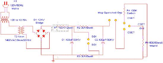
– From: Tad Johnson ; Subject: ERE Produced by Accident Date: Thu Feb 13, 2003 2:18 pm
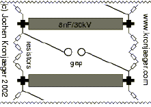
(Tad Johnson) Have a look at the bottom of the page explaining the “problems” Jochen has found when firing this 300KV Marx generator. Looks to be what we are after since he cannot seem to eliminate it through grounding and other means. Also look at the total conduction times (64uS) with rise and fall times substantially lower possibly in the 5-10uS range.
http://www.kronjaeger.com/hv/hv/pro/marx/index.html
The discharge seems to induce huge voltage transients in ground and/or mains leads. This has resulted in a burnt mains switch and a destroyed ground fault interrupter. Grounding the Marx generator separately and decoupling the charging voltage ground with a resistor helps somewhat. This may turn out to be a major problem, as the Marx generator naturally produces a huge voltage step with a rise-time probably in the microsecond range, and the subsequent discharge produces a similarly steep current pulse which might be kA or more.
(Tim Martin) Do you have a plan to allow for easily adjusting the frequency of the impulses? I it will be important to precisely tune the device so as to discern specific effects.
(Tad Johnson) The frequency is adjustable to a degree through adjustment of the spark gap distance and cap size. The caps I am using are 500pF so frequency should be in the KHz range depending on how much amperage the power supply is charging the stack with. Just got the HV resistors today. All I have left to do is build the CSET and figure out the charging circuit.
Hydrogen or magnetically quenched gap on the output might frequency and more protection against current reversals.
– Subject: folder added Hi folks, Date: Sat Feb 15, 2003 11:52 am
(Jani V.) I thought you might like to see my version on Ed Grays circuit In folder “romisrom” I just created, are some pictures of it, I will add complete schematic with component data as soon as I’m able to draw it…
Tad, I hope from picture “convtube” you will find some hints for your CSET. -Jani-
– Subject: CSET design Date: Sun Feb 16, 2003 8:28 pm
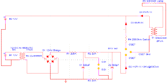
(Tad Johnson) Thanks for the info. I was going to built it similarly although I was going to use 1.250″ acrylic I have already to center the copper pipe. I have some new info on my power supply I will post soon. Looks like the rise time will be ~10nS with a pulse width of 50uS and a fall time of 40uS without a tailbiter circuit or resistive load of about 0.1Ohm to sharpen the fall time. I may add this later. Frequency should be about 25Khz as is.
– Subject: Tesla/Gray device update Date: Thu Feb 27, 2003 7:08 pm
(Tad Johnson) My Gray device is now operational although I have foolishly fried a couple of neon sign transformers in the process of trying to loop the collection grid energy back to the power supply without some form of isolation circuitry. It appears I am now at the point that Gary Magratten was when trying to deal with a large pulse of energy and then measure it.
Current circuit parameters are:
2000VAC @ 19.2Khz @ 20mA into a 12KV/40mA/100nS full wave bridge into a 2 stage marx generator using 400pF/ 30KV ceramic “doorknob” caps into a magnetically quenched spark gap using needle points of brass into the CSET of stainless steel balls on threaded brass rods. Collection grid is 316 stainless 2″ diameter tube.
Total output pulse is 54uS wide with ~10nS rise and ~42nS fall.
I am thinking of running the output energy in the secondary of a 3KV microwave transformer to power a lower voltage load although I am not sure how the transformer secondary will handle this input, especially considering the frequency. Another option would be to increase cap size on the marx generator portion of the circuit to lower the frequency to something around 60- 120Hz and then use it in a more conventional form.
Pictures and schematics to come soon. Any ideas are much appreciated. Tad
– Date: Fri Feb 28, 2003 8:25 pm
(Tim Martin) I have a few questions. Is it possible to safely measure the voltage and frequency of the CSET output?
(Tad Johnson) Yes, I got the data below by making a 50Megaohm resistor to measure it, although I am reluctant to hook up the 3500 dollar scope to it as of yet. I get more guts to do so after I check the warranty info on it. All data thus far was taken on a true RMS LCR meter.
What is the AC current draw of the neon sign transformer? (Tim Martin)
Should be 1.5 Amp per the specs. But I will check it with my true RMS power-meter(5amp max on the meter).
(Tim Martin) Would it be possible to dump the CSET output into a large lead acid storage battery? (MDG nov07: Ed Gray is reported to have exploded batteries with the Radiant Energy Spikes of too high voltage, so be careful)
(Tad Johnson) Yes, although I am told it will “cold boil” at that voltage. Seems to be hard on the battery but I don’t have much knowledge on it. I would like to step the voltage down before connecting it to the battery to avoid premature failure.
(Tim Martin) Would the neon sign transformer work properly if connected to a small >DC/AC inverter on the 12 volt battery?
(Tad Johnson) Should.
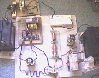
– Subject: Gray Circuit Images Date: Sat Mar 1, 2003 10:19 pm
(Tad Johnson) New images uploaded showing the Gray circuit running after being tuned. Having issues with long runs because the resistors are not rated for more than 10watt on the Marx generator, they start to get a bit hot. Images show a 120VAC/60HZ/1.5A neon transformer powering it since my two other 12VDC inverters were smoked due to bad judgment. No connection to the CSET grid was present during this test run since I was mostly tuning the Marx stack to the 120V neon supply. Frequency was .5-1Khz on this test.
New power supply got here today so I will try the 12VDC version charging the Marx stack at higher frequencies (20Khz).
Flash on the camera makes it hard to see arc across gaps, but it is there.
Total cost of the entire device is now about $145 American dollars.
– Subject: Re: [ElectroRadiantResearch] Re: Gray Circuit Images Date: Sun Mar 2, 2003 4:36 pm
(Tim Martin) I noticed in your pictures that you do not have a large high voltage air core as Gray and Magratten used in their circuits. Is this un-necessary?
(Tad Johnson) I am told the air core was a step down to run 120VAC/60HZ lamps and other resistive loads since resistive loads don’t care about frequency. I haven’t built an air core step down yet, but I might if I can’t get a motor built soon.
(Tim Martin) Also, what did you say the clear “Plexiglas” material is? Real Plexiglas(tm) in those dimensions is fairly costly.
(Tad Johnson) Acrylic. Resists about 50KV in that dimension 1-1/8″ thick. Very inexpensive. 1.5’X 1.5X square is 20 dollars. I used about half of one.
– Subject: Grid Energy Date: Sun Mar 2, 2003 11:02 pm
(Tad Johnson) Interesting findings after running the Gray circuit for a couple hours:
ERE does NOT manifest if there is no resistor on the spark gap end of the CSET. Repeat ZERO POWER if no resistor in place. The more resistance, the more the effect appears to manifest.
With 300 Ohm or more of resistance the grid starts to put off a FRIGHTENING amount of power.
Enough to smoke a 50watt, 500 ohm resistor in less than 30 seconds. My input was 12 watts total from the wall. Output from the CSET grid is UNMEASURABLE. Grounding is also becoming an issue since I cannot run the end of the CSET back to ground with a resistor in between. Also,the energy coming off the grid appears to be harmful even with fast rise and fall times contrary to other information out there.
Anyone have any bright ideas on measuring this high amperage, high voltage energy I would be very happy. We need accurate wattage out at this point. I feel confident already with my input measurements.
– Subject: Re: [ElectroRadiantResearch] Re: Grid Energy Date: Mon Mar 3, 2003 11:05 am
(Tim Martin) It sounds as though Lindemann was correct in saying that one of the problems Gray had was dealing with the abundance of power.
(Tad Johnson) Yes, but we will see how much power. This is what I am after. If it is possible for a small 12 watt power supply to see a gain of at least twice that, then making the circuit for the application I am interested in will be easy (small motive power, scooter, etc.).
(Tim Martin) Do you think the CSET output is behaving different than “normal” electricity?
What I am curious about is your statement regarding additional resistance increasing the effect.
(Tad Johnson) It appears as though there MUST be resistance at the end of the CSET in order for the CSET grid to make power. this appears to be the “bunching up” effect Lindemann was talking about, and that Tesla had experienced. It may be that when this HV pulse hits the resistance is like it hits a brick wall and explodes outward into the grid (path of least resistance).
(Tim Martin) Also, I believe that the frequency will govern whether or not the effect is harmful. Be careful!
(Tad Johnson) I’m being as careful as I can, but I have already had one small incident.
(Tim Martin) Another thing you might try is placing a normal 100 watt incandescent bulb on the output of the CSET without closing the circuit. Single wire power transmission is a related phenomenon.
(Tad Johnson) Yes, this works with a neon bulb, I’ve already run neon bulbs off the grid energy. they glow beautifully to full brightness.
– Subject: Fwd: Re: [alfenergy] Grid Energy Date: Sun Mar 2, 2003 11:35 pm
(Willard)I can suggest putting a string of light bulbs together in series as a load. 5 bulbs of 100 watts each for instance.
(Tad Johnson) I will try that although I really need to somehow get an amp meter on it and the scope. I had to drop the voltage down from 2920 to 1460 just so I could lessen the effect enough to work with the components I am using without it destroying them. Meter overloads when trying to measure grid voltage on the doubled setting from the Marx generator. I am using a 100Megaohm, voltages. Very strange.
– Subject: Re: [alfenergy] magnetic quenched gap Date: Tue Mar 4, 2003 11:35 am
(Peer) The magnetic quenched gap is necessary to prevent continuously arcing. Is this right?
(Tad Johnson) No, it helps quench the arc, and bring the fall times back to something more normal. The waveform as per calculations is ~10nS rise, 50uS wide, with a long fall time, this is how Marx generators work. To bring the fall time back into ~20nS range we need to clip the end of the pulse. You can do this by killing the arc prematurely or you can put a low resistance load on the output of the spark gap (tail-biter circuit), or you can do both. My goal was ~10nS rise, 20uS pulse, ~20nS fall, with a pause of 500uS between pulses.
– Subject: Re: [alfenergy] for Tad Date: Wed Mar 5, 2003 11:44 am
(Unknown Member) I’m trying to rebuild your circuit in order to better understand the working of the CSET. The original circuit built by Gray himself had a powerful input. Heavy batteries were used to power the circuit. You only use a small current und a much higher resistor at the CSET.
(Tad Johnson) Yes, my idea is to keep the power usage as low as possible but still see the effect. And I have truly seen it with a 9-12 watt power supply, so it IS there. I am now lighting neon bulbs from the grid energy alone, this should not be possible since it would mean an energy gain of at least 100%, or an additional 9 watts to make a total of 18watts for the entire circuit.
http://www.amazing1.com/voltage.htm
At the bottom of the page you will see the power supply I am currently using (MINIMAX2)
(Unknown Member) I try to copy your circuit, using a medium size 6,5kV HeNe-LASER supply. output (grid-power) I get, is however tiny small.
(Tad Johnson) That’s fine, my supply I use now is only 1460V @ 8mA!! But this voltage is doubled in the Marx generator. The Marx generator is used instead of the large capacitor and vacuum tube switch in the Gray patents. This eliminates the need for expensive and complicated switching techniques since the Marx generator switches on in less than 50nS and off in that same amount of time unless you are running larger capacitors. 400pF caps @ 1460V @ 8mA gives me 500HZ. But 1900pF in that same supply only gives me about 1-2HZ, but much higher amperage pulse when the gap fires. If more amperage in the power supply (like 20mA) then this rate would obviously be much higher and much more controllable.
http://home.earthlink.net/~jimlux/hv/marx.htm [Appendix 1]
http://members.tm.net/lapointe/MarxMain.html [Appendix 2]
http://www.kronjaeger.com/hv/hv/src/marx/index.html [Appendix 3]
(Tad Johnson) The capacitors come from: http://www.alltronics.com/capacito.htm
The 400pF 30KV ones are $12.50 each. The 6.5KV 1500pF are 99 cents each. The cheaper ones work just as well if not better! If you really want a big power pulse buy the 14uF, 20KV, 2800 joule cap!
– CERAMIC HI-VOLTAGE TRANSMITTING CAP 400pF @ 30KV, TC N4700. Made by TDK. 20P007 $12.50
– SANGAMO ENERGY DISCHARGE CAPACITOR 14 uF 20KV 2800 Joule 14″ x 8″ x 24″ — Mineral oil filled ; 20P002 $250.00
– (Unknown Member) Maybe there is a secret I have not seen yet. My CSET is not a pipe, but a round cage made by copper wire soldered together. If a measurable radiant energy is made, this one I guess should be noticed by the small CSET grid I have.
(Tad Johnson)You WILL see energy on that grid regardless of it’s design. I am using a stainless tube, but any copper, aluminum or anything else should work also. Multiple layers of different metals (copper inside, aluminum outside should increase power as well).Also, move the CSET spark gap into the tube like Skip said. I should have done this as well, but I was lazy. This should maximize the energy on the grid. Use a couple neon lamps to run off the grid. 220VAC @ 10mA is what my bulbs are, I use two in series and they light up to full brightness off the grid energy alone. One lead to grid, one to ground. They light to half brightness just touching the grid and not grounded. I am trying to figure out what I was doing when I ran the 50watt resistor across the grid output in order to get it as hot as it was getting. This circuit grid output varies greatly depending on how it is tuned so there are many things to test still.
I really want to try a flyback supply soon though. http://www.electronicsic.com/fly.htm
– (Unknown Member) Maybe my quenched spark gap is not working. How is yours built up?
(Tad Johnson) I used a block of plastic on both sides and used a Forstner bit (1/2″) to core a hole in the plastic, then I used glue to glue the ceramic magnet into the hole on both pieces of plastic. Then I used a router to make a slot so I could adjust the magnet distance from the gap electrodes. The magnets TWIST the arc and cut it off early, This gives us a faster fall time.
(Unknown Member) Have you enclosed the R4 inside the CSET tube or outside? Is it a high voltage type or a normal one?
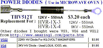
(Tad Johnson) Outside and it is a normal 10K, 3 watt resistor, made by Panasonic, ordered from Digikey. The same resistors are used in the Marx stack. I have also tried a HVR-1X, 12KV/550mA diode (THV512T is new part number). This works well also. http://www.electronicsic.com/diode.htm
– Subject: Gray Circuit Modifications Date: Wed Mar 5, 2003 11:18 pm
(Tad Johnson) I finished my circuit modifications as per suggestions. I tripled the capacitance in the Marx bank, installed the CSET gap in the center of the collection grid and added a 25nF cap on the output of the CSET grid in line with the load. The lamps glow at least as twice as bright as they did before. But what is really exciting to me was that I was going to work on the Marx gap so I went to short the cap bank. At the instant I shorted this bank of caps I felt the “wave of energy” which actually pushed my shirt in the direction of the blast.
Has anyone else seen this when discharging a cap bank and being of close proximity? Very strange anomaly. Makes me believe that Tesla must have been working with much higher voltage and much higher capacity than this circuit in order to feel this wave constantly at each gap firing. This is obviously what we are looking to reproduce.
– Subject: Re: [alfenergy] Magnetic Quenched Gap Date: Thu Mar 6, 2003 9:16 am
(Alan Francoeur) I have tested the function of a magnetic quenched gap. I used a Marx generator to create short HV pulses. The spark gap was simple two ends of a copper wire facing each other with a distance of about 2 mm. I used a vice and put a strong Neodymium magnet at each side of the vise jaw. The gap between the two magnets was about 17 mm. (The magnets were attracting each other) the arrangement was so that you could easily remove the vice with magnets without changing the spark gap.
Without magnets an arc occurred many times after a spark and the frequency of the spark was changing all times and there was a small interval without a spark, partially. From that view I can conclude the spark gap without magnet is not so well functioning because of the lower spark frequency and the occurring arcs.
(Tad Johnson) Yes, I have found this myself as well. This is why I like the magnetic gap so much.
(Alan Francoeur) With the magnets, the spark’s frequency was higher, and there was no standing arc at all. Each time an arc liked to occur the arc got blown out like a candle in the wind.
When I was connecting a small (8 Watt) neon-bulb between the vice ,which was made of steel and somehow served as grid, and ground the neon-light lit weekly and the ark frequency changed a bit also the ark noise changed! And this although there is no galvanic contact between the Marx generator and the neon-bulb.
(Tad Johnson) I don’t understand why frequency changes when you connect a load to the grid, but I have seen this as well.
(Alan Francoeur) But I also measured the current flowing back to ground after the mentioned spark gap. This was done by a 50 Ohm resistor a HV-probe and an oscilloscope.
(Tad Johnson) I am making a new HV probe, 1GOhm will be the size. A bit high, but I have many problems with the 100MOhm one I use now.
(Alan Francoeur) Without magnets: the time duration of the spark could be hardly measured but seemed to be >500 ns.
With magnets: the time duration of the spark was definitely shorter and the picture on the scope was more clear. The time duration was 100 us to 200 ns.
(Tad Johnson) Great! This is what we are after.
(Alan Francoeur) In both cases, you see a positive high voltage pulse that exceeds the capacity of the screen of the scope. Then a small negative pulse, like the half of a sine wave, follows. After that there are fast oscillations. Maybe this picture does not show the true current flow, because of parasitic capacities of the used resistor.
(Tad Johnson) The ringing is what has been messing my frequency counter up I think. I might not be getting the correct frequency of pulses measured. Inductors can be used in place of the resistors to reduce loss, although the output will obviously be different and need to be rectified or sharpened up.
(Alan Francoeur) Another investigation was, that using no magnet, a multi-discharge could occur (many tiny discharges). With magnet there was always one discharge. Maybe you have the same experience.
(Tad Johnson) Yes, exactly. This is why Tesla also used these magnets around the gap. He was trying for a smaller and tighter discharge of energy.
(Alan Francoeur) Tad, have you tried to put magnets inside the gray tube? Therefore you would not need to have a separate spark gap and maybe more power inside the Gray tube.
(Tad Johnson) I have not tried this yet, but I can try it soon.
– Subject: Progress Date: Thu Mar 13, 2003 10:42 pm
(Tad Johnson) No progress on the Gray circuit this week as I have been working on getting a lathe to make parts and do better quality work so I have not been financially able to buy the HV resistor for measurement nor the Thyratron, or spark tubes.
I pulled my Hydrogen combustion enhancement device out of the shop since fuel prices are getting ridiculous. Car already gets 33mpg, but 38-40 would be better.
I will put pictures of it when I get it running again. I will be working on the Gray circuit again within a week or two though. Stay tuned,
– Subject: Re: [ElectroRadiantResearch] Success ??? Date: Fri Mar 21, 2003 9:17 pm
(Jani V.) Last weekend I finally got a chance to test my Ed Gray-machine and I think the Electro-Radiant-Event manifested once. When I ran the test, 40 W light bulb flashed before the whole bunch of charge, which was collected to the grids, discharge though the safety spark gap (schematic Test1a, look my folder romisrom ). I tried to duplicate the Radiant-Event but it didn’t manifest again. I think the interrupter-rotating rod burned somehow because it’s resistance raised near two meg-ohms!!! I also have to make the carbon resistor different because it is not very stable, resistance range between 50 – 500 ohms depending temperature.
I’ve also added in the spark-gap a strong NIB magnet to cut arc more faster. I think this magnetically quenched spark is very important to produce ERE. Anyway, test must be done again to make sure that it was ERE that manifest neither some other discharge…….unfortunately my testing is very slow because I live in another place due to my work and my test equipment are another place. So, it may take awhile.
(Tad Johnson) Congratulations!, sounds like a successful test run. You should get constant power off the grid once the circuit is tuned and stabilized. 300 Ohms on the end of the CSET seem to be perfect in my last test run.
Keep up the good work, no matter how slow it goes, it’s worth it to humanity.
Note: This document is one in a series produced by Mr. McKay as part of his investigation of the work of Edwin Gray senior and he invites readers to contact him if they have any constructive comments or queries concerning the work of Mr. Gray. Mr McKays e-mail address is mmckay@tycoint.com
## Part 6: Conversation between Mark Gray and Mark McKay on 5/19/07, ‘McKay6.pdf’, 10pages, 623kb, from files of the YahooGroup ‘alfenergy’
Mark Gray is E.V. Gray’s 6th child born in 1958 in southern California. For the past several years he has been a parts-room manager for a school district repair shop which maintain over 200 buses. He is a single parent who currently lives with his three yound adult children. (Two daughters and one son).
Mark was employed by his father, E.V. Gray, for the majority of the time between 1979 and early 1988. In this time period, he served in the capacity of a general assistant. He traveled and worked at seven different locations, including a two weeks long trip to Israel.
Under his father’s direction he assisted in the building of the majority of the ‘Trigger Carts’ (The converter systems under the pulse motors) that are displayed in the 1986 ZTEX promotion video. He also assisted in securing parts from custom vendors, video taped the technology, assisted with various demonstrations, drove the company truck, and wrote licensing agreements. These are just a few of the multitude of tasks he did during his tenure of service.
Mark parted on good terms from his father in early 1988 when funding ran out due to differencies between E.V.Gray and certain investors, over the control and future of the technology. These differencies were heightened when alleged government contact, interested in a possible R&D program on the switching/triggering aspect of the technology, came into the picture late 1987 – early 1988.
While Mark had a tremendous exposure to his father’s later technology (1979-1988), his detailed understanding of the underlying functioning principles is almost gone. He did what he was told to do and was compensated appropriately for his services, but never got deeply involved with the workings of the technology. For the past twenty years Mark has been completely divorced from his father’s technology and has forgotten almost everything he knew about it. He regrets not having paid more attention and not having taken a real interest in the ‘nuts and bolts’ of the process.
Mark was most willing to share these anecdotal technical Tid-Bits that might have a bearing on rediscovering this lost technology.
The Mark I (Converter Switching Element Tube)
# The cylindrical glass enclosure is a Colman gas lantern cover
COMMENTARY: THis really limits the magnitude of the internal pressure of what ever have been present. The size of the end caps could support pressures up to 6000 psi. With such a thin glass envelop anything over 3psi would be difficult.
‘He didn’t want to pay the high price for a machined enclosure’
# all electrical connections were made from the top
COMMENTARY: I only see two electrical connections at the top of this device (the balck center conductor and the white conductor with the large yellow single pin connector. Therefore the ‘Grid’ is not connected to anything, unless it is connected to one of the electrodes.
# the gap was adjustable
# the internal gas was presumed to be Nitrogen from a welding supply house
COMMENTARY: Mr. Gray was very familiar with welding gasses.
‘He didn’t get involved with anything that exotic’ (referring to S6F)
# Purpose of the Grids: ‘Possibly to cover up something he didn’t want people to see?’
COMMENTARY: Like an additional series component, perhaps an HV RF coil?
# Was there an electrical connection to the Grids? ‘I don’t recall’
# ‘The electrodes were made of Tungsten or Titanium. Which ever material Russia is famous for.’ [Titanium]
The Mark II ‘Silver Cylinder’ (Ignition):
# This was an off the shelf commercial device that was a metal cylinder about 2″ in diameter and 6″ long.
# The terminal insulators were glass
# It was a two terminal device only, with wires connected to the top and the bottom.
# The round flanges were custom made end pieces to secure additional finned aluminum heat sinks that were attached around the periphery.
# The band in the center was a radiator clamp to hold it all together. Sometimes two clamps were used.
# These units did occasionally wear out or fail. New units were stocked on the shelf
# These devices contained Mercury and therefore retired units were treated with respect in storage.
# When this units arced inside you could see a blue flash through the terminal glass.
COMMENTARY: It appears these devices are Class A Ignitrons. They are the right size, right from factor and contain Mercury. However an Ignitron is a three, or more, terminal device. It operates much like a very high current thyratron. If there were no control connections for the igniter, then one use might have been a fixed-distance spark gap and just overvoltaged until it fired. One advantage of this approach would be a clean Mercury surface after each pulse. The pulse rate observed in the 1986 video is on the order of 2Hz.
It is unclear wither these ignitrons were a replacement for the CSET or components in adition to the CSET. So far, the best explanation supports the idea that the ignitrons replaced the function of the rotating spark gaps that were in the commutator section of E.V. Gray’s early motor design. The 1986 Promotion Video will show that Gray used several of these devices for his motors (up to six per cart). Gray probably developed a new system where the complexity of the old front end rotary spark gap array was no longer needed, thus greatly reducing the fabrication costs per motor.
Magnet wire for the Popping Coils:
# All the wire for the construction of the projectile coils was standard copper magnet wire.
# One company was contracted to machine the aluminum or plastic coils forms (Normally Nylon). Another company was hired to wind the coils. ‘We attempted to wind a few of our coils. But not many.’
We used in special places:
‘That wire there was the expensive silicone filled wire that had to be used at that connection’ pointing to the photo of the battery charger converter and the wires coming off the storage capacitor.
COMMENTARY: In the Cannady Interview it was noted how ‘Cold Electricity’ would destroy the insulation on conductors. Apparently Gray did find a tentative solution to this problem by using special wire in the locations where it was required.
A trip to the capacitor vendor: Mark Gray recounted an experience he had when he was instructed to return some defective capacitors to a custom supplier in Southern California.
The internal connection between the external capacitor terminal and the internal plates had opened up because the wire gauge was too small, thus causing it to fail. To explore this complaint first hand, the vendor opened up one defective unit with a can opener. Since the connection had been separated at this point there was still a substantial charge still left in the unit. There was an unexpected accidental discharge that caused a loud bang. Apparently the vendor quickly made repair modifications to all of the returned capcitors at no charge. Mark reports that the plates were gary layers of a white material in between them. The entire unit was filled with a thick clear gel. Mark Gray claims he recalls values of 500mF at 5kV.
COMMENTARY: This type of construction implies a low inductance plate capacitor rather that the higher inductance rolled designs. The residual stored charge implies a low loss construction. I don’t know about the dielectric, it could have been a standard poly material. Another authority claims Gray used Mica. I don’t know what color mica is when installed in a large capacitor.
‘Cold Electricity’ is also known for its loud discharges.
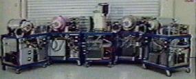
The Trigger Cart:
Mark Gray claims that the heart and soul of the E.V. Gray technology is the ‘Trigger Cart’. This is the power supply that was the source of the anomalous energy for all of the projectile demonstrations. What is interesting about this system, is that it operates from 200V AC, counter to all of E.V. Gray’s previous motors and circuits.
COMMENTARY: Some researchers have proposed that the Gray technology required the use of wet cell lead-acid batteries for the generation of ‘Cold Electricity’. Apparently this is not the case with the existence of this cart. However, the overall OU qualities of this technology may be impaired with the use of utility power. But at the time, E.V. Gray was seeking military customers who could benefit from the propulsion features of this equipment.
Trgigger Cart Operation: ‘Slowly crank up the Auto-transformer unitl the tubes started to fire, then watch the volt meter. When it got to 5,000 Volts I would quickly turn down the Auto-transformer and fire the projectile.’
COMMENTARY: In the background sound of the demonstration video we hear about 20 pops before the projectile is ready for launch. It seems E.V. Gray was discharging one capacitor into another capacitor. Once this charging operation was complete he would discharge the collected anomalous energy through his opposing coils to launch a projectile. I don’t know what he used for a discharge switch.
If Mark Gray was reading an analog voltage meter then we can be pretty sure that the anomalous ‘Cold Electricity’, when stored in a capacitor, can be observed as a positive classical voltage. This is very consistent with Tom Bearden’s description of ‘Negative Mass Energy’ – if the two phenomena are at all related. Earlier photos show E.V. Gray using an analog Triplett 630-A multimeter to measure the voltage of ‘Black Boxes’ that are assumed to be storage capacitors in his early ‘Popping Coil’ demonstrations (1973).
If the Pops we hear (20 or so per launch) are from the four Ignitrons on top of the cart, then it is reasonable to assume that the source DC supply voltage was in excess of 5kV. If the ignitrons were connected so that they would self-trigger by connecting the igniter to the anode, then there would be a sudden break-over pulse every time the voltage difference between the anode and cathode reached about 1500V DC. This would imply that the source supply voltage was at least no lower than 8kV.
Since there was a concerted effort to turn down the auto-transformer after reaching 5kV, I would guess that E.V. Gray was charging his custom capacitors right to their design limits.
Auxiliary Capacitors:

COMMENTARY: In this photo, note the Projectile Cart on the left. Six different types of projectile are launched from this demonstration platform. The bottom of this cart contains a pretty substantial capacitor bank array. You can see only 70% of the cart.
This would imply that there are about 9 large capacitors in the first rank. If two rows are employed, then a total of 18 capacitors are needed. I suppose this sort of stored energy was needed to support the Hover demonstrations or the large 71 lb launch.
Mark Gray claims that this cart was in E.V. Gray ‘s possession at the time of his death. He plans to enquire among family members as to where this piece of equipment went.
COMMENTARY: It is my contention that if this cart was saved from the one way trip to the surplus re-seller, then who ever got it couldn’t make it operatinal. According to Mark Gray, his father spent his last days disassembling this equipment. This system would be high on the list of things to do first.
Split the Positive? :
When asked if his father ever told him about the fundamental energy conversion process Mark Gray recalled one experience where his father told him ‘The energy starts from the positive terminal [of the storage capacitor/dipole] than part of it goes back to the supply battery and part of it goes to the load.
COMMENTARY: This type of topology is shown in patent 4-595-975, but the actual technical meaning is anybody’s guess.
The Wireless Projectile:
Mark Gray claims that some potential investors would ask ‘What good is this system if you have to have wires connected to projectile? That is not going to work’. So he developed this demonstration apparatus to show that the projectiles really didn’t need wires. Actually, they are needed for only a short distance, beyond which the magnitude of the repulsive forces drops off quickly. The above setup provided a sliding contact that is in the little black and white tower on the left of the larger black cylinder. This arrangement allows for about 6-8″ of travel before electrical contact is broken. By that time, the travelling mass has received most of the shock impulse it is going to get. The black repulsing coils are composed of copper magnet wire that is about 2″ deep. The outside is covered with black vinyl elctricians tape. Mark also said that it was hard to reconnect the sliding contact because of rotation after a shot. Apparently it took a broom stick and a ladder to rest the demo.
COMMENTARY: The measurable voltage of the energy that propelled the small black cylinder on top with the (white plastic saucer on the bottom) was said to be 5kV. Now look at the length of the arc trail [about 12″] of the little contact tower (at the left) after lift-off. Consider what kind of voltage was being generated at this point.
The state of the storage batteries prior to a test od demonstration for a Motor Cart:
‘When a motor cart was prepared for a test (or demonstration) both sets of batteries were fully charged’.
COMMENTARY: So much for the idea of having to start with a dead battery. This theory comes from the idea that the lead-sulfite was the medium that might have converted a pulse of classical electricity into ‘Cold Electricity’.
Another Cold Electricity Demo using the ‘Start Motor’:
The white round instrument sitting on top of the ‘Start Motor’ on the Multi-demonstration Cart is a thermometer. The other round dial instrument lying down on the table just below the round rheostat is a mechanical RPM indicator. [Biddle Meter]
The importance of the Spark Gap: E.V. Gray told Mark Gary that the spark gap was vey important.
COMMENTARY: A lot of other researchers tink so too.
Motor Names: While the older E.V. Gray motors were numbered, the newer versions in the 80’s were named according to a color. There was the Red Motor, the Blue Motor, the Purple Motor, the White Motor and the Black Motor. Each one was intended to demonstrate some particular aspect of this technology or head off any common questiona that had continually arisen over the years.
Stump the Expert Time: Once, a professional researcher, from MIT, was allowed to examine the equipment while development was taking place in Canyon Country, CA, (possibly for some investor review). He had flight arrangements to leave the following Monday and had the whole weekend plus a day for his investigation. Apparently there were no restrictions placed on what he could look at. This man was leeged to be one of the two co-inventers who developed the first anti-shark repellants. He examined and observed for at least one whole day and then made a comment to the effect, ‘If I can’t figure this out, then all of my academic training is wothless’. He worked all through the weekend and left the following Monday with no tentative classical explanation.
COMMENTARY: It would sure be nice to see if this individual would grant a phone interview. I’m sure he didn’t talk a whole lot about this experience when he returned to Boston. I wonder if he would now?
Other questions asked through e-mail:
– To your knowledge did your father (or his assistants) own or use any of these common electronics shop instruments?
Oscilloscope, Radio Frequency (RF) Generator, General Signal Generator, Pulse Generator, Transistor Tester, Q-Meter, Grid Dip Meter, Frequency Meter, Digital Counter, Capacitor Tester, Battery Tester, Spectrum Analyzer, DC Power Supply.
Of course any information about a general description, perhaps a Make and Model number (ha,ha), and an idea as to what the instrument was used for. When it was used and by whom.
Response: 1) There were some meters involved, but I do not remember what meters might have been used or for what they would have been used for.
Question 2) The ‘kernel’ of the technology appears to reside on the circuit trigger boards and the specific wiring to the off board components. From the photos we know that large power transistors were used. It is pretty obvious that other board components were used as well.
Silicon Controlled rectifier (SCR), Control Relays, Large Power Resistors, Transformers, Inductors or Chokes, Radio Frequency Coils, Vacuum Tubes, Diodes, Rectifiers, Power MOSFETS, Veristers, Potentiometers – Variable Resistors, Others, Model number of Power Transistors?
Of course a general description, approximate count, and any idea as to their function would be helpful.
Response 2) The most knowledgeable on the circuits boards may be Nelson ‘Rocky’ Shlaff (or Schlaff) from the Los Angeles area. I do remember that the circuits boards were developed in Canyon Country and for a while the services of an electronics consultant was acquired to help development some of this circuitry. I do not remember the name of the consultant.
Qyestion 3) We know that you did a majority of the work on this equipment.
Was there any specific part of these ‘Carts’ that your father reserved for himself to work on exclusively?
Response 3) Actually, my father did not protect any specific area of any of the technology that I can remember. Many people had cast their eyes on and all over the technology that was built. Nelson Schlaff and myself did most the assembly of the technology. There were others from time to time that were involved with the technology built.
Question 4) Concerning the ‘Trigger Cart’. You said that during its operation you would charge a certain capacitor to 5,000 Volts before launching a projectile. you also said the voltage input was 220VAC. Here are some general questions about the over all construction of the cart.
What Size Breaker was needed to power the ‘Trigger Cart’ 30Amp, 40Amp, 50Amp, higher?
Was a transformer use to raise the voltage from 220VAC to a higher voltage?
If 5,000 Volts was the final measurable output voltage, then was there a higher voltage used somewhere else in the circuit that you know of?
Were Inductors or Chokes included on this Cart?
Did you ever have to make repairs on the Trigger Cart, if so what was replaced and how often?
THere are 4 Ignitrons on the Trigger Cart. Were all of these used at all times, or did different demonstrations use a different number of these devices?
Response 4) The only thing I remember about the voltage was charging the capacitors to 5,000 V ?? for a one-time discharge (propulsion of a magnet), however, the hovering of magnets was achieved by a constant firing of the tubes.
Question 5) Concerning the origins and nature of the transistor circuit boards used for the ‘converters’.
Were these circuits made in house or contracted out? Did you make them? Did the design change over the years? If these boards failed who repaired them? Were replacements kept on hand?
Response 5) I do not recall much, if any was needed, maintenance on the circuit boards, nor do I recall having any made up as spares. I believe that all R&D and constructions of the technology happened in-house.