http://users.skynet.be/fa272699/Energie/Meyer/memos/section2.pdf
WATER FUEL CELL
Quenching Circuit Technology ; Rendering Hydrogen Safer Than Natural Gas
The Quenching Circuit Technology is a combination and integration of several Gas-Processes that uses noncombustible gases to render hydrogen safer than Natural Gas.
The, “Non-Burnable” gases are used to adjust hydrogen “Burn-Rate” to Fuel-Gas burning levels … recyc1ed to stabilize Gas-Flame temperatures .. .intermixed to sustain and maintain an hydrogen Gas-Flame … and used to prevent Spark-Ignition of supply gases.
The utilization and recycling of the non-combustible gases allows the Water Fuel Cell to become a Retrofit Energy System.
The Quenching Circuit Technology is systematically activated and performed in the following way:
Operational Parameters
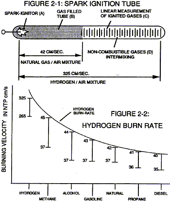
Spark-Ignition Tube
Spark-Ignition Tube (B) is a tubular test apparatus (1/8 diameter) that determines and measures the “Bum-Rate” of different types of Burnable Gases intermixed with Ambient Air, as illustrated in Figure (2-1).
Spark-Ignitor (A) causes and starts the Burnable Gas-Mixture (B) to undergo Gas-Ignition which, in turns, supports and allows Gas Combustion to take place … forming and sustaining a Gas-Flame. The expanding and moving Gas-Flame travels (away from spark-ignitor) the linear length of the gas filled tube (C) and is “detected” and “measured” (length between spark-ignitor and light-detector) in one second after gas-ignition. The Gas-Ignition Process, now, establishes the “Burn-Rate” of a Burnable Gas-Mixture in centimetres per second (cm/sec.), as illustrated in Figure (2-2).
Different types of “Burnable” Gas-Mixtures exposed to the Gas-Ignition Process were tested, measured, recorded and systematically arranged as to cm/sec. length, see vertical bar Graph (2-2) again. The Gas-Ignition Process was performed several times to establish the “average” Burn-Rate of the Fuel-Gases which, in turn, establishes the length of the vertical bars.
Gas Injection Process
Injecting and intermixing a Non-Combustible Gas (D) (non-burnable gas) with the ‘Burnable” Gas-Mixture (B) “changes” or “alters” the gas-mixture “Burn-Rate”. Increasing the volume-amount of Non-Combustible Gas (D) diminishes and/or lowers the “Burn-Rate” of the Gas-Mixture (B/D) still further. Progressive and controlled intermixing of the non-combustible gases (B/D) allowed the “Burn- Rate” of Hydrogen to be “lowered” or “adjusted” to “match” or … equal” the “Bum-Rate” of other Fuel-Gases, see curve line in Figure (2-2).
In terms of operational performance, the Non-Burnable gas (D) does “Not” support the Ji5 Combustion Process since the Non-Burnable Gas (D) “restricts” or “retards” the speed at which the Oxygen Atom unites with Hydrogen Atoms to cause Gas Combustion. The “Gas Retarding Process” is, of course, applicable to any type or combination of Burnable Gases or Burnable gas-mixture.
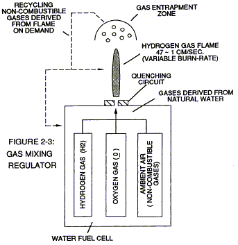
Gas Mixing Regulator Inherently, the Water Fuel Cell allows the “Burn-Rate” of Hydrogen to be “Changed” or “adjusted” from 325 cm/sec. to 42 cm/sec. (Co-equalling Natural Gas Burning levels) since Non-Combustible Gases (such as Nitrogen, Argon, and other non-burnable gases) derived from Ambient Air dissolved in natural water performs the Gas Retarding Process … sustaining and maintaining an Open-Air Flame beyond 5000-degrees F, as illustrated in Figure (2-3)
Natural water acts and performs as a “Gas-Mixing Regulator” when the Fuel-Cell is electrically energized by way of voltage stimulation (Electrical Polarization Process) …. producing a uniform gas-mixture (B/D) regardless of the Gas Flow-Rate of the Fuel-Cell producing a uniform gas-mixture (B/D) only when needed. In quiescent-state, the supply of gases (BID) being released from the water bath is “terminated” and “stopped” when the Fuel-Cell becomes “deenergized”.
The unused water, of course, remains as a non-burnable liquid. The gases (B/D) above the water bath is “vented” for safety purposes.
Flame Temperature Adjustment
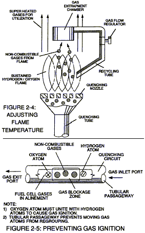
By capturing and recycling the expelled non-combustible gas (D) (derived from and supplied by the water bath) back into the sustained hydrogen gas-flame or Fuel-Cell causes the gasflame temperature to be “changed” or “altered” by way of the Gas Retarding Process, as illustrated in Figure (2-4) as to Figure (2-3). The recycling gases (D) controlled by an Gas Flow Regulator allows the gas flame-temperature to be “adjusted” or “calibrated” to any gas burning level (S), as so illustrated in Figure (2-2).
The “newly” formed and established gas flame-temperature remains constant regardless of the gas flow-rate of the Fuel-Cell. Continual feedback of non-combustible gases (D) is, hereinafter, called “The Gas Combustion Stabilization Process”. Automatically, the Gas Combustion Stabilization Process changes the “Burn-Rate” of the Fuel Cell gases (B/D) when obtaining the desired gas-flame temperature.
Quenching Circuit
Spark-Ignition of the Fuel-Cell gases (B/D) is prevented when the “Gas Retarding Process” is used in conjunction with a “Quenching Circuit”, as illustrated in Figure (2-3), (2-4), (2-5) and 26).
The non-combustible gases (D) separates and prevents the hydrogen atoms to unite with oxygen atoms to “bring-on” or “initiate” Gas-Ignition. The narrow passaway (at least 1/8 inch long and having a .015 diameter) prevents the moving gas atoms from “Re-Grouping”. The alignment of the Fuel-Cell gases (BID) inside the tubular-passaway is, hereinafter, called “The Quenching Circuit”. The Quenching Circuit “Anti-Spark technique” is “independent” of both Gas-Velocity and Gas-Pressure.
Quenching Nozzle
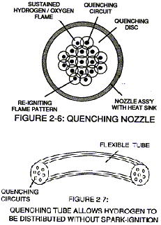
Additional Quenching Circuits arranged in a Disc-shape configuration forms a “Quenching Nozzle” when attached to an “Quenching Tube”, as illustrated in Figure (2-4) as to Figure (2-6). The Multi Gas-Port Disc compensates for increased Gas-Velocity while “preventing” spark-ignition of the Fuel-Cell gases. The overlapping Flame-Pattern re-ignites the expelling hydrogen gas-mixture (B/D) should Flame-Out occur. Ceramic material is used to form the “Quenching Disc” to “prevent” hole-size enlargement due to gas-oxidation.
The non-combustible gases (D) keeps the Ceramic Material “cool-to-the-touch” by projecting the Gas-Flame beyond and away from the disc-surface … the Quenching Disc remains “cool” even if the Gas-Flame Temperature exceeds the melting-point of the disc-material.
Quenching Tube
The Quenching Disc is extended into a Flexible Tube to transport the Fuel-Cell gases safely over long distances, as illustrated in Figure (2-7). The Spark-Arresting Gas-Line is, hereinafter, called “The Quenching Tube.”
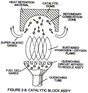
Catalytic Block Assembly
An Inverted hemispherical cavity placed on top of and in space relationship to the “Quenching Disc” insures total gas-combustion by recycling any “escaped” or “unused” burnable gases back into the gas-flame for Gas-Ignition … preventing Gas-Oxide formation, as illustrated in Figure (2-8) as to Figure (2-4).
Internal Combustion Engine
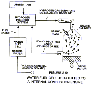
The Gas Combustion Stabilization Process (recycling non-combustible gases) is also applicable to operating an Internal Combustion Engine without changing Engine-Parts since the Gas Retarding Process allows the hydrogen “Burn-Rate to “equal” the “Burn-Rate” of Gasoline or Diesel-Fuel, as illustrated in Figure (2-2). The engine provides its own non-combustible gases derived from Ambient Air undergoing the gas-combustion process. Engine temperature remains the same since The Gas Stabilization Process is used.
Gas Grid System
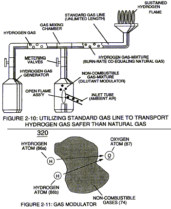
Ambient Air is the prime source of Non-Combustible Gases when the Air-Gases are exposed to and passes through an Open-Air Flame, as illustrated in Figure (2-10). The Gas Combustion Process of the Gas-Flame eliminates oxygen and burnable gas atoms from the expelling gases … producing an endless supply of non-combustible gases.
Mixing the “processed” Air-Gases with an Hydrogen Supply Source sets up The Gas Retarding Process … allowing the Hydrogen Gas-Mixture to be transported safely through existing Gas-Grid System.
Operational Parameters
The utilization and recycling of non-combustible gases, now, renders hydrogen gas as safe as Natural Gas or any other Fuel-Gas … allowing the Water Fuel Cell to become a Retrofit Energy System.