MEMO 3, Memo WFC 422 DA
http://users.skynet.be/fa272699/Energie/Meyer/memos/section3.pdf
WATER FUEL CELL
WFC Hydrogen Gas Management System ; Water Fuel-Gas Injection System ®
The WFC Hydrogen Gas Management System encompasses many processing patents into a full system-engineering approach to help give a viable answer to the energy problem … by using “Water” as a new Fuel – Source.
The WFC Hydrogen Gas Management (GMS) System not only economically produces “Hydrogen – Fuel” on demand from water but, also, renders Hydrogen – Fuel safer than natural gas … allowing cars, trucks, or even jets to run on or be powered by water.
The WFC Hydrogen Gas Management (GMS) System is systematically activated and performed in the following ways as a retrofit energy – system … defining ” Mode of Operability” on how to use “Water” as Fuel.
Laser Accelerator Assembly (20)
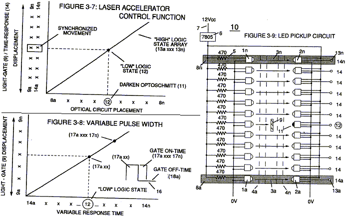
Laser Accelerator Circuit (10) of Figure (4) which is a component part of Laser Accelerator Assembly (20) of Figure (3-10) uses a Gas infrared emitting diode (1) of figure (3-9) to trigger a SDP8611 Optoschmitt light receiver (2) of Figure (3-9) from quiescent state ( output logic high … B+) (13) to on-state ( the minimum irradiance that will switch the output low) which switches or triggers the Optoschmitt (2) output to ground state (zero volts) (12). The peak wavelength (3) of Figure (3-9) being transmitted from the infrared emitting diode (led) (1) to the Optoschmitt receiver (2) is typically (935 nm) and allows the Optoschmitt (2) clock frequency (the speed by which the Optoschmitt changes logic state) to be (100 kHz). Optical lens (4) of Figure (310) redirects and focuses the transmitted light source (3) of Figure (3-9) (traveling infrared light waves) to the Optoschmitt (2) by passing the light source through a series of concentric lenses (4a xxx 4n) of Figure (3-10) which become progressively smaller from the outer peripheral lens surface (4a) to the inner lens surface (4n).
The spatially concentric lenses (4a xxx 4n) of Figure (3-10) causes the beam angle of the light source to trigger the Optoschmitt (2) beyond the minimum irradiance that is needed to switch the Optoschmitt from quiescent state (high logic state I B+ ) to on-state (output changing to zero volts).
The Derate linearly of light intensity is approximately 1.25mWj degree C above 25 degree C at a spatial distance of .500 inches between the two infrared devices (1)(2) of Figure (3-9) as to Figure (3-10). Transmitted light source (3) is turn-on when an electrical power source of 5 volts is applied to the led (1) through dropping resister (5) by way of voltage regulator (6) connected to the car electrical system (7). Together, the matched infrared devices (1)(2) with optical lens (4) forms optical circuit (8) of Figure (3-9). Grouping additional optical circuits (8a xxx 8n) in a inline or linear arrangement, now, forms Led Pickup Circuit (10) of Figure (3-9), as shown in Figure assembly (20) of Figure (3-10).
To perform a switch-logic function, light – gate (9) of Figure (3-9) as to Figure (3-10) is inserted between the matched infrared devices (1)(2) and moved in a linear displacement from one optical circuit (8x) to another optical circuit (8xx), as illustrated in Figure (3-9)(3-10) as to Figure (3-7). Once light-gate (9) blocks and prevents traveling light-beam (3) from reaching the matched Optoschmitt (8xx), the darken Optoschmitt (11) (non-energized) changes output state since the irradiance energy level (3) is reduced to, or below the release point…triggering opposite logic state (12). As light-gate (9) advances to the next optical circuit (8xxx) a new and separate low-state logic function (12) occurs while the previous optical circuit (8xx) revens back to high-state logic (13). Advancing light-gate (9) still further performs the same opposite (alternate) logic-state switching in a sequential manner until the advancing light-gate (9) reaches the last optical circuit (8n). Reversing the movement of light gate (9) performs the same high to low logic switch-function but in reverse sequential order. Reversing the direction of the light-gate (9) once again reinstates the original sequential switching order, as illustrated in Figure (3-7) and Figure (3-9).
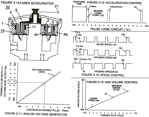
Longevity and reliability of component life is typically 100,000 hours since led pickup circuit (10) of figure (3-9) utilizes no mechanical contacts to perform the sequential logic switch function. Light-gate (9) integrated with led pickup circuit (10) make up Laser Accelerator assembly (20), as shown in Figure (3-10). Light-gate (9) of Figure (3-10) is mechanically linked to the car acceleration pedal by way of cabling hookup (22).
Opposite placement of the matched infrared devices (1)(2) prevents bogus or false triggering of “low” logic state (12) during light-gate displacement (9a xxx 9n) of Figure (6)(7) and (8). If light emitting diodes (led) (la xxx In) of figure (8) are electrically disconnected from D.C. power supply (6), then Led Pickup Circuit (10) outputs are switch to “low” logic state (l2a xxx 12n) which disallows “low” logic state signal (12), resulting in a “shut-down” condition to Hydrogen Gas Control Circuit (200) of Figure (3-1). Disconnection of power supply (6) to Optoschmitt array (2a xxx 2n) of Figure (3-9) results in a similar “shut down” condition to control circuit (200), as further shown in Figure (3-1). This “shut-down” or “Switch-off” condition helps provide a fail-safe operable Fuel Cell (120) of Figure (3-20) by negating acceleration beyond driver’s control.
Acceleration Control Circuit (30)
Moving light-gate (9) of figure (3-9) in direct relationship to the physical placement of optical circuits (8a xxx 8n), sets up a time variable (14a xxx 14n) of Figure (3-7) from optical circuits (8x) to another optical circuit (8xx) and/ or (8xxx) or to (8n) since the triggered low logic state (12) of Figure (3-7) and (3-8) moves in direct relationship to the displaced light-gate (9), as illustrated in Figure (3-12). Deflecting (moving) the light-gate (9) to position (8n) takes longer in response-time (14n) than deflecting the light-gate to position (8x) and/or (8xx) or (8xxxx). This variable response-time (14axx … 12 … xxI4n) or signal output (15) of Figure (3-5) is, now, electrically transmitted to Acceleration Control Circuit (30) of Figure (3-5) since Laser Accelerator Assembly (20) of figure (3-10) converts mechanical displacement (9a xxx 9n) to electrical time-response (14a xxx 14n) of Figure (3-7) by linearly moving (forward and/or reverse direction) “low” logic state signal (12) in a array of “high” logic state output signals (13a xxx 13n), as further illustrated in Figure (3-8) and Figure (3-12). In some cases reverse signal-logic (12a xxx … 13 … xxI2n) is applicable by using SDP 8601 Optoschmitt which switches logic state from Quiescent state (“low” to “high” logic state) when de-energized.
Since Led Pickup Circuit (10) of Figure (3-9) operates up to 100 kHz range or above, electrical sensitivity of Opto-circuit (8) provides an instantaneous response to Driver’s acceleration, de-acceleration, or cruise control demands.
As signal output (15) of figure (4) (14a xxx … 12 … xxI4n) is being received by acceleration control circuit (30) of Figure (3-5) as to Figure (3-12), circuit (30) converts incoming time – response signal (14a xxx … 12 … xxI4n) into a variable time-base unipolar pulse (16), as shown in Figure (3-8). Circuit (30) electronically and automatically scans output signal-array (14a xxx … 12 … xxI4n) (15) until circuit (30) locates, momentarily registers, and translates responsetime (14a xxx … 12) into a variable unipolar pulse (17/18) of Figure (3-8). The sweeping action of the scanning circuit (30) always starts from position (9a) and moves point (8ax) to point (8axxx) of Figure (3-9) (3-12) until logic-point (12) is detected. Once logic signal (12) is detected, the sweeping action toggles and recycles back to start-position (9a). This toggling (flip back) action electronically determines variable time-response (14a xxx) regardless of wherever logic point (12) is being momentarily displaced within circuit array (13a xxx 13n).Toggling action at full-scale deflection (13a xxx 13n) occurs in the range of (10) kHz or above and thus, allows instant response to Driver’s acceleration demands.
Toggling-time (scanning -time) is directly synchronized to light gate (9) displacement which, in turns, circuit (30) further sets up and establishes a given pulse shape (16) of Figure (38). Circuit (30) continues to increase pulse width (17axxxx) of Figure (3-8) as the monitored (detected by scanning) toggling-time (14a xxxx … 12) ) increases when logic-point (12) moves farther away from start-position (9a) to stop-position (9n), as further shown in Figure (3-13) as to Figure (3-12). Pulse width (17a xxx 17n) diminishes when logic-point (12) reverses direction to start .. position (9a). Finally, circuit (30) reproduces the variable controlled pulse-shape (16) in a continuous repetitive manner (16a xxx 16n) of Figure (3-13) and electrically transmits the resultant pulse-train signal (19) to Analog Voltage Circuit (40), as shown in Figure (3-5).
In retrospect to engine performance (gas pedal attenuation) (21) of Figure (3-10), a wider pulse width (17a xxx) of Figure (3-13C) increases (accelerates) engine R.P.M.; whereas, smaller pulse-width (17ax) reduces (de-accelerates) engine R.P.M .. Cruising speed (3-13B) of Figure (3- 13) is simply accomplished when pulse width remains constant.
Incoming clock pulse (21a xxx 21n) of Figure (3-16) originating from Pulse Frequency Generator (70) of Figure (3-5) sets up the scan-rate (toggling) by which signal input (15) of Figure (3-5) is electronically scanned by circuit (30). The resultant clock pulse (21) of Figure (3-16) as to Figure (3- 5) is always adjusted to exceed driver’s response time to allow for instant acceleration control.
Analog Voltage generator (40)
The generated digital signal (19) being electrically transmitted from accelerated control circuit (30) of Figure (3-5) is, now, electronically detected, translated, and converted into a analog voltage signal (22) which is continuously proportionate to input signal (19) by analog voltage Generator Circuit (40) of Figure (3-5). The newly formed analog signal (22) of Figure (3-14) is a voltage level signal that varies continuously in both time and amplitude to produce a voltage level which is directly proportional to the physical change in pulse train (100 xxx 16n) of Figure (3-13). As pulse width (17ax) of signal (19) changes so does analog voltage level output (23) of Figure (314). Widening pulse width to stopposition (17a xxxx 17n) of Figure (3-13) causes analog signal (22) to increase to higher voltages levels; whereas, analog voltage level (22) drops (become lower in value) in voltage level when pulse width decreases to start-position (17a). The resultant and varied voltage level (22a xx) varies smoothly over a continuous range of voltage valves (22a xxx 22n) rather than in discrete steps, as illustrated in linear graph (23) of Figure (3-14).
In terms of functional ability and purpose, analog circuit (40) of Figure (3-5) provides a variable (controlled) voltage output (23) in direct relationship to light gate (9) displacement which, in turns, sets up and controls Resonant Action (160) of Figure (3-23) that produces Fuel Gases on demand. Analog circuit (40) also calibrates both engine idling speed (22ax) and maximum engine R.P.M. (22a xxx 22n) by adjusting and maintaining a predetermined or given low (24) and high voltage levels respectively, as further illustrated in Figure (3-14). Voltage valves or levels (22a xxx 22n) simply controls the applied voltage potential across Resonant Cavity Assembly (120) of Figure (3-22) through voltage amplitude control circuit (50) of Figure (3-5) which is is electrically linked to primary coil (26) of Figure (3-21) of Voltage Intensifier Circuit (60) of Figure (3-5).
Voltage Amplitude Control Circuit (50)
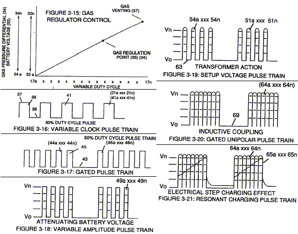
Voltage amplitude control circuit (50) of Figure (3-5) performs several functions simultaneously: First, regulates car battery electrical voltage potential (32) of Figure (3-15) being applied to primary coil (26) of Figure (3-21); and secondly, regulates gas pressure of Fuel Cell (120) of Figure (3-22), as graphically depicted in Figure (3-15). Each regulatory stage (27) and (28) works separately and independent of each other but are electronically linked or coupled together to produce a common analog signal (32) having a predetermined voltage level (32a xxx), as further shown in Figure (3-15).
Regulator stage (27) of circuit (50) converts battery voltage potential (29) of Figure (3-6) via electrical terminal (31) of Figure (3-5) as to Figure (3-6) into a analog voltage signal (32) of Figure (3-15) which corresponds to but is electrically isolated (crossover voltage from two separate power supplies) from incoming gas volume signal (23) of Figure (3-14), as shown in Figure (35). Variable voltage range (32a xxx 32n) from one (1) up to twelve (12) volts (regulating battery voltage) is applied across primary coil (26) of Voltage Intensifier Circuit (60) of Figure (3-21). Second regulator stage (28) simply acts and function as a gas regulator (33) by preventing Fuel Gas production beyond a predetermined gas pressure level (34) of Figure (3-15) during Fuel Cell operations and, as such, maintains constant gas pressure to Fuel Injectors (36) of Figure (3-1) regardless of engine performance (R.P.M. response). If for example, Fuel Gas production is greater than demand, then, analog signal (32) is reduced to proper voltage level (35) (voltage level directly determines gas pressure via Resonant Action) required to maintain gas pressure (34), Conversely, analog signal (32) is always allowed to exceed voltage level (35) during injection (36) of Figure (3-1) until gas-point (34) is reached. In cases where linear voltage (32) drops (descending value) below gas-point (35) then gas regulator stage (28) increases voltage amplitude (32a xxx 32n) (analog voltage) to voltage point (35). If gas pressure (34a xx) should exceed gas point (35) during injector off-time, gas pressure release valve (75) of Figure (3-24) (gas venting 37 of Figure 3-15) expels Fuel gases (88) until gas point (34) is either reach or a delay timing circuit activates Safety Control Circuit (14) of Figure (3-6) which, in turns, switches off or disconnects applied electrical power (28) to Fuel Cell electrical system (400) of Figure (3-6).
Gas logic circuit (310) of Figure (3-5) supplies logic function to Voltage amplitude control circuit (50) to maintain proper gas pressure to gas injector (36) of Figure (3-1) by electronically monitoring achieved gas pressure via pressure sensor (73) of Figure (3-24).
In terms of operability, Laser Accelerator Assembly (20) of Figure (3-5) is, now, attenuating battery voltage potential (32a xxx 32n) which is electrically connected to voltage Intensifier Circuit (60) of Figure (3-5).
Variable Pulse Frequency Generator (70)
Circuit (70) of Figure (3-5) is a multi pulse-frequency generator which produces several clock pulses (simultaneously) having different pulse-frequency but maintaining a 50% duty cycle pulse (39) configuration, as illustrated in Figure (3-16). Pulse on-time (37) and pulse off-time (38) are equally displaced to form duty pulse (39) which is duplicated in succession to produce pulse train (41) of Figure (3-16). Increasing the number of duty pulses (39axxx 39n) up to pulse frequency range of 10Khz or above now forms clock signal (21) of Figure (3-5) which, in turns, performs the scanning function of Acceleration Control Circuit (30) of Figure (3-5). Circuit (70) also produces another independent and separate clock signal (41a xxx 41n) which is electrically transmitted to and become incoming clock signal (42) for Gated Pulse Frequency Generator Circuit (80) of Figure (3-5). In both cases, pulse frequency range of each clock signal (21) and (42) can be altered or change (controlled independent of each other) to obtain peak performance of Fuel Cell System (100) of Figure (3-5).
Gated Pulse Frequency generator (80)
Gated Pulse Circuit (80) of Figure (3-5) switches “off’ and “on” sections of incoming clock signal (42) to form gated pulse (45) which is, in turn, duplicated in succession to produce gated pulse train (46a xxx 46n) of Figure (3-17). Together pulse train (44a xxx 44n) and pulse offtime (43) forms gated pulse duty cycle (45). Pulse train (44a xxx 44n) is exactly the same as pulse train (41a xxx 41n) and its established pulse frequency (number of pulse cycles per unit of time) changes uniformly when pulse generator (70) of Figure (3-5) is calibrated and adjusted for system operations.
Newly formed gated duty pulse (45) is proportional to the physical change in pulse train (44a xxx 44n) when circuit (80) is adjusted for calibration purposes. Pulse train (44a xxx 44n) becomes widen while pulse off-time width (43) becomes smaller, simultaneously. Conversely, opposite pulse shaping occurs when circuit (80) of Figure (3-5) is calibrated in reverse order.
Cell Driver Circuit (90)
In either case, the resultant or varied pulse train (47a xxx 47n) (calibration of 44a xxx 44n) becomes incoming gated pulse signal (48) of figure (3-5) to cell driver circuit (90) of Figure (3-5) which performs a switching function by switching “off’ and “on” electric ground being applied to opposite side (48) of primary coil (26) of Figure (3-19). The resultant pulse wave form (49a xxx 49n) of Figure (3-18) superimposed onto primary coil (26) is exact duplicate of proportional pulse train (47a xxx 47n). However, each pulse train (47) (49) are electrically isolated from each other. Only voltage cross-over from regulated power supply (150) of Figure (3-6) to battery supply (28) occurs, as illustrated in Figure (3-6).
Voltage Intensifier Circuit (60)
By integrating and joining together variable voltage amplitude control signal (318 xxx 32n) of Figure (3-15) with variable controlled switch-gate (49a xxx 49n) of Figure (3-18) across primary coil (26) of Figure (3-22), variable amplitude pulse-train (51a xxx 51n) of Figure (3-19) is electromagnetically coupled (transformer action) to secondary coil (52) of Figure (3-22) by way of pulsing core (53) of Figure (3-23) as to Figure (3-22).
Analog voltage signal (32a xxx 32n) of Figure (3-15) allows pulse train (51a xxx 51n) voltage amplitude (VO xxx Vn) of Figure (3-19) to vary from one up to twelve volts (battery supply28 of Figure 3-6 ) by attenuating Laser Accelerator circuit (10) of Figure (3-5) via Hydrogen Gas Control Circuit (100). Variable pulse frequency generator (70) of Figure (3-5) varies and adjusts pulse frequency (63) (50% duty cycle pulse) while gated pulse frequency generator (80) of Figure (3-5) varies and adjusts pulse width (54a xxx 54n). These controlled and variable pulse features are, now, translated to Resonant Charging pulse train (65a xxx 65n) of Figure (3-21) via Unipolar pulse train (64a xxx 64n) of Figure (3-20) during Resonant Action (160) of Figure (3-26) when signal coupling is applied across Resonant Cavity (170) of Figure (3-24) via positive voltage zone (66).
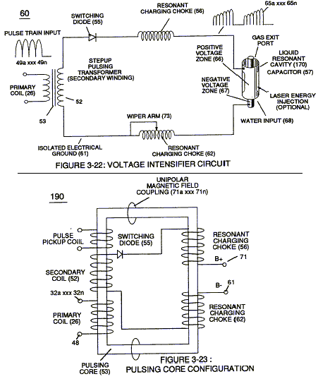
Negative electrical voltage potential (61) of pulse wave (65a xxx 65n) of Figure (3-21) is simultaneously applied to negative voltage zone (67) via Resonant Charging Choke (62) of Figure (3- 22) which is electrically linked to opposite end of Primary Coil (26). The resultant signal coupling ( 65a xx 65n ) of Figure (3-21) is accomplished since primary coil (26), pulsing core (53), secondary coil (52), switching diode (55), resonant charging choke (56), resonant cavity assembly (170), natural water (68), and variable resonant charging choke (62) forms Voltage Intensifier Circuit (60) of Figure (3-22), as illustrated in Figure (3-22) as to Figure (3-23). Negative electrical ground (61) of voltage Intensifier circuit (60) of Figure (3-22) is electrically isolated from primary electricaI ground (48) of Figure (3-22).
Pulsing transformer (26/52) of Figure (3-22) steps up voltage amplitude or voltage potential (VO xxx Vn) of Figure (3-19) during pulsing operations. Primary coil (26) is electrically isolated (no electrical connection between primary _26 and secondary coil ~ to form Voltage Intensifier Circuit (60) of Figure (3-22). Voltage amplitude or voltage potential (Vo xxx Vn) is increased when secondary coil (52) is wrapped with more turns of wire. Isolated electrical ground (61) prevents electron flow from input circuit ground (48).
Switching diode (55) of Figure (3-22) not only acts as a blocking diode by preventing electrical “shorting” to secondary coil (52) during pulse off-time (69) of Figure (3-20) since diode (55) “only” conducts electrical energy in the direction of schematic arrow; but, also, and at the same time functions as a electronic switch which opens electrical circuit (60) during pulse offtime … allowing magnetic fields of both inductor coils (56/57) to collapse … forming pulse train (64a xxx 64n).
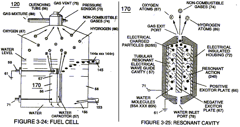
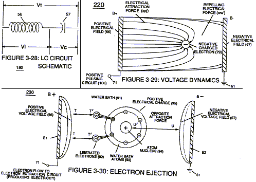
Resonant charging choke (56) in series with Excitor-Array (160) of Figure (25) forms an inductor-capacitor circuit (180) of Figure (3-28) since Excitor-Array (66/67) acts and performs as a capacitor (dielectric liquid between opposite electrical plates) during pulsing operations. The dielectric properties (insulator to the flow of amps) of natural water (68) of Figure (3-28) as to Figure (3-26) (dielectric constant of water being 78.54 @ 20C in 1-atm pressure) between electrical plates (66/67) forms capacitor (57) , as illustrated in (170) of Figure (3-25). Water now becomes part of Voltage Intensifier circuit in the form of “resistance” between electrical ground (67) and pulsefrequency positive potential (66) … helping to prevent electron flow within pulsing circuit (60) of Figure (3-22).
Inductor (56) and capacitor (57) properties of LC circuit (180) is therefore “tuned” to resonant at a given frequency. Resonant frequency (63) of Figure (3-19) can be raised or lowered by changing the inductance (56) and/or capacitance (57) valves. The established resonant frequency is, of course, independent of voltage amplitude, as illustrated in Figure (3-21) as to Figure (3-18). The value of inductor (56), value of capacitor (57), and the pulse-frequency (63) of voltage (Yo xxx Vn) being applied across the LC circuit determined the impedance of LC circuit (Figure 3-28).

The voltage across inductor (56) or capacitor (57) is greater than applied voltage (49) of Figure (3-18). At frequency close to resonance, the voltage across the individual components is higher than applied voltage (49), and, at resonant frequency, the voltage (Vt) of Figure (3-28) across both inductor and the capacitor are theoretically infinite. However, physical constraints of components and circuit interaction prevents the voltage from reaching infinity.

During resonant interaction, the incoming unipolar pulse train (64a xxx 64n) of Figure (320) as to Figure (3-21) produces a step charging voltage effect across excitor-array (66/67) (57) as so illustrated in Figure (3-21). Voltage intensity increases from zero “ground-state” to an high positive voltage potential in an progressive function. Once voltage-pulse (64) is terminated or switch-off, voltage potential returns to “ground-state” (61) or near ground-state (diode _55 maintains voltage charged across capacitor _57 ) to start the voltage deflection process over again as pulse train (64a xxx 64n) continues to be duplicated.
“Voltage intensity or level across excitor anay (57) can exceed 20,000 volts due to circuit (60) interaction and is directly related to pulse train (64a xxx 64n) variable amplitude input. Inductor (56) is made of or composed of resistive wire to further restricts D.C. current flow beyond inductance reaction (Xl), and, is given by (Eq 8)

Variable inductor-coil (62) of Figure (3-22), similar to inductor (56) connected to opposite polarity voltage zone (67) further inhibits electron movement or deflection within voltage intensifier circuit (60). Movable wiper arm (73) of Figure (3-22) fine “tunes” “resonant action” during pulsing operations. Inductor (62) in relationship to inductor (56) electrically balances the opposite electrical potential across voltage zone (66167).
Since pickup coil (52) is also composed of or made of resistive wire-coil, then, total circuit resistance is given by (Eq 9)

Whereby, electrical power (P) is a linear relationship between two variables, voltage (E) and amps (I). Amp restriction beyond “resonant action” occurs when unipolar magnetic field coupling (71) of Figure (3-23) is allowed to simultaneously drop (pulsating magnetic field) across both resonant charging chokes (56/62) during pulsing operations since electron mass is a electromagnetic entity which is subject to inductor fields (56/62) produced by pulsating magnetic field (71a xxx 71n) of Figure (3-23). Amp leakage (electron coupling to water) to water bath (68) of Figure (3-24) is further prevented by encapsulating resonant cavity (57) in delrin material (72) of Figure (3-25) which is an electrical insulator to high voltage. Delrin material (72) insulator value remains intact since insulation material (72) is resilient to water absorption.
Inherently, then, pulsing core (53) of Figure (3-23) aids amp restriction while voltage intensifier circuit (190) is being “tuned” (adjusting pulse train 49a xxx 49n pulse-frequency 63 via pulse frequency generator 70 of figure 3-5 ) to match the resonant frequency properties of water bath (68) of Figure (3-22), as illustrated in Fuel Cell (120) of Figure (3-24). The resultant interfacing voltage circuit (190), now, exposes water molecule (210) of Figure (3-27) to a pulsating high intensity voltage field (65a xxx 65n) of opposite polarity (66/67) while restricting amp flow within circuit (60) of Figure (3-22).
Voltage Dynamics
Voltage is “electrical pressure” or “electrical force” within electrical circuit (60) and is known as voltage potential (65a xxx 65n) of Figure (3-21). The higher the voltage potential (VO xxx Vn), the greater “electrical attraction force” (qq’) or” electrical repelling force” (ww’) of Figure (3-29) is applied to electrical circuit (60) of Figure (3-22). Voltage potential (65) is an “unaltered” or “unchanged” energy-state when “electron movement” or “electron deflection” is prevented or restricted within electrical circuit (190) of Figure (3-23).
Unlike voltage charges within electrical circuit (60) steps up “electrical attraction force” (qq’); whereas, like electrical charges within the same electrical circuit (60) encourages an “repelling action” (ww’), as illustrated in Figure (3-29). In both cases, electrical charge deflection or movement is directly related to applied voltage (65). These electrical “forces” are known as ‘voltage fields’ and can exhibit either a positive (66) or negative (67) electrical charge.
Likewise, Ions or charged particles (atoms having missing or sharing electrons between unlike atoms) within electrical circuit (60) having unlike electrical charges are attracted to each other. Ions or particles mass having the same or like electrical charges will move away from one another, as illustrated in (220) of Figure (3-29).

The potential at a point to a charge (q) at a distance (R) in a medium whose dielectric constant is (e).
Electrically Charged Water Molecule
Atomic structure of an atom (76) and (77) of Figure (3-27) exhibits two types of electrical charged mass entities, orbital electrons (79) having negative electrical charges ( – ) and a nucleus (84) (at least one proton) having a positive electrical charged ( + ). The positive electrical charge of the nucleus equals the sum total of all negative electrical charged electrons when the atom is in “stablestate.”
In stable state or normal-state, the number of electrons equals the number of protons to give the atom “no” net electrical charge.
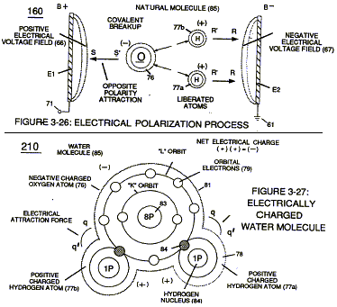
Whenever one or more electrons are “dislodged” from the atom, the atom takes-on a net positive electrical charge and is called a positive ion. If a electron combines with a stable or normal atom, the atom has a net negative charge and is called a negative ion. “voltage potential (65) within electrical circuit (60) can cause one or more electrons (79) to be dislodged from the water molecule atom (85) of Figure (3-26) due to opposite electrical polarity attraction (qq’) of Figure (3-29) between unlike charged entities, as shown in (160) of Figure (326) as to Newton’s and Coulomb’s laws of electrical-force. These same laws of electrical-force (qq’) is used to combine or join atoms together by way of covalent bonding (opposite electrical forces) to form a molecule of water (85), as illustrated in (210) of Figure (3-27).
The liquid molecule of water (210) of Figure (3-27) is formed when the two hydrogen atoms (77a1b) takes-on a net “positive electrical charge” (78), which is, equal to the net “negative electrical charge” (81) of the oxygen atom (76). The resultant electrical force (qq’) between the opposite electrical charged hydrogen (77) and oxygen (76) atoms keeps water molecule (210) intact when the hydrogen atom (77) shares its electron (84) with oxygen atom (76). The electrical strength of attraction force (qq’) between the water molecule atoms is determined by the electrical size of the hydrogen atoms and the displacement of its negative charged electrons (84) during covalent sharing.
Oxygen atom becomes negative electrical charged (81) since oxygen atom (76), now, has a total of ten negative charged electrons (79a xxx 79n) in its “K” plus “L” orbits while maintaining it’s original eight positive charged protons which makes up oxygen nucleus (83). Since the hydrogen proton (84) (hydrogen nucleus) remain (after covalent link up), then the hydrogen atom takes-on a positive charged (78) co-equalling the positive charge of the hydrogen nucleus proton (84). Together, the total net charge of water molecule (85) is zero despite the fact that each water molecule atom retains its electrical charge. In other words, water molecule (85) is a electrically bipolar molecule having a stable configuration of charged atoms bound together by electrostatic force (qq’). Electromagnetic bonding forces between unlike atoms (76n7) are negligible or non-existence, since oxygen atom (76) electrons are paired together, while rotating in opposite direction which, in turn, causes oxygen atom (76) to be electromagnetically neutral to hydrogen atom (77). Electron theory of magnetism requires orbital electrons to spin in the same direction before an atom can exhibit a electromagnetic field. Furthermore, external electrical force (66/67) can alter the electromagnetic properties of a atom since electromagnetic force is dependent on the movement of charged particles in a electrostatic field. voltage Intensifier circuit (190) of figure (3-23), now, allows voltage to dissociates water molecule (85) by overcoming electrostatic bonding force (qq’) between unlike atoms (76n7) while restricting amp flow, as illustrated in (160) of Figure (3-26).
Electrical Polarization process
Placement of a pulse voltage potential (65) across Excitor plates (El!E2) (voltage zones 66/67) of Figure (3-29) as to Figure (3-26) while inhibiting and preventing electron flow within voltage intensifier circuit (190) of Figure (3-23) causes water molecule (210) of Figure (3-27) to separate into its component parts (released hydrogen and oxygen gases) by pulling away (utilizing opposite attraction forces SS’ and RR’) its charged water molecule atoms (76n7), as illustrated in (160) of Figure (3-26).
Stationary “positive” electrical voltage-field (66) (voltage plate El) not only attracts negative charged oxygen atom (76) but also pulls away negative charged covalent electrons (84) from water molecule (210). At the same time stationary “negative” electrical voltage field (67) (voltage plate E2) attracts positive charged hydrogen atoms (77a/b). Once negative electrically charged oxygen atom (76) is dislodged from water molecule (85), covalent bonding (sharing electrons between atoms) ceases to exist, switching-off and disrupting electrical attraction force (qq’) between unlike atoms (76/77), as further illustrated in (160) of Figure (3-26).
Opposite polarity electrical attraction force (SS’) continues to cause negative charged oxygen atom (76) to migrate to positive voltage-plate (E1) (positive voltage zone 66); while, at the same time, opposite polarity electrical attraction force (RR’) causes positive charged hydrogen atoms (77a/b) to migrate in the opposite direction to negative voltage-plate (E2) (negative voltage zone 67) as step-charging voltage-wave (65) increases in voltage amplitude from several millivolts to several hundred volts during each pulse train (65a xxx 65n) which, in application, causes water molecule (210) of Figure (3-27) charged atoms (76/77) to elongate (increasing distance between unlike atoms 76/77) to the point where covalent hydrogen electrons (84) of Figure (3-27) breaks away from electrostatic force (qq’). Repetitive duplication of voltage pulse (65a xxx 65n) continues to separate or split apart other water molecules (85a xxx 85n) which, in turns, forms hydrogen (86) and oxygen (87) gas-mixture (88) of Figure (3-24).
Dissociation of water molecule (85) by way of voltage stimulation (65) is herein called “The Electrical Polarization Process”, as illustrated in (160) of Figure (3-26).
Resonant Action
Subjecting and exposing water molecule (85) to even higher voltage levels (xxx Vn) (up to and beyond several thousand volts) causes water bath (91) of’Figure (3-30) as to Figure (3-25) to go into a state of ionization by allowing opposite polarity forces (TT’) and (UU’) to eject one or more electrons (92a xxx 92n) from water bath atoms (93). Intensified electrical attraction force (TT’) causes dislodged negative charged electrons (92) to migrate to positive voltage-plate (El) while electrical attraction force (UU’) causes positive charged atom nucleus (94) to travel toward negative voltage-plate (E2). Applied electrical attraction force (TT’) and (UU’) always being of equal voltage intensity but opposite in electrical polarity as voltage amplitude (65) is attenuated.
Replication of higher voltage forces (TT’) and (UU’) during pulsing operations causes a continued release of other electrons (92a xxx 92n) from other water bath atoms (93a xxx 93n) which, in practice, increases electrical charges of water bath (91) since water bath (91) is a dielectric liquid. Water bath atoms (93a xxx 93n) having missing electrons (92) take-on a positive electrical charged (95) which is subject to and moved by negative electrical force (UU’); whereby, the liberated and free floating negative charge electrons (92) are subject to and move by positive electrical force (TT’). Applied together, electrical forces (TT’) and (UU’), now, causes these moving electrically charged particles to superimpose a physical impact unto electrical polarization process (160), as shown in (170) of Figure (3- 25) … thereby, increasing gas-yield (88) still further.
By attenuating voltage amplitude (VO xxx Yn) in conjunction with pulse-width (65a xxx 65n) allows voltage intensifier circuit (190) of Figure (3-23) to tune-in and match the resonant characteristics or resonant frequency of water bath (91) since water bath (91) always maintains its dielectric properties during pulsing operations. At resonance, electrical polarization process (160) interacts uniformly with liberated charged particles (92/95) of Figure (3-25) to obtain a even higher gas-yield (88) at maximum voltage deflection (xxx Vn).The established resonant frequency is most generally in the audio range from 1 Khz up to and beyond 10 KIlz; and is dependent upon the amount of contaminants in natural water. Oscillating and superimposing electrical charged particles unto the Electrical Polarization process at a given pulse-frequency is, now, herein called “Resonant Action”, as illustrated in (240) of Figure (3- 25).
To reach maximum gas-yield (88) resonant cavity (170) of Figure (3-25) is shaped into a tubular structure (typically 0.50 inch diameter tube inserted into 0.75 inch diameter tube having a .0625 concentric air-gap 3 inches long) which functions as a longitudinal wave-guide to enhance particle movement in a lateral or angular displacement to applied voltage fields (66/67). Insulated housing (72) prevents voltage coupling to water bath (68) which allows applied voltage amplitude (xxx Vn) to remain constant across water molecules (85a xxx 85n) … stabilizing gas production during voltage stimulation (65), as shown in (120) of Figure (3-24). To further prevent voltage fluctuation during resonant action, Phase Lock Loop technique of Pulse Indicator circuit (110) is utilized during pulsing operations. The resultant fuel-gas (88) is, now, transferred through Quenching Tube (96) of Figure (3-41) to, through and beyond Fuel Injectors (36) of Figure (3-1) for Hydrogen gas utilization.
In cases where applied voltage amplitude is to remain constant while promoting Resonant Action during control-state, incoming pulse train (64a xxx 64n) is varied independent of voltage amplitude to attenuate voltage intensity (66/67) which, in turns, effect gas production. In other applications, Voltage amplitude (66/67) in direct relationship to pulse-train (64a xxx 64n) may be varied together in a progressive manner to further control gas production. Or pulse-train (64a xxx 64n) can remain constant while voltage amplitude is varied. In all cases, Resonant Action is being promoted to product hydrogen gas on demand.
In terms of Longevity, voltage zones (E11E2) are composed of or made of stainless steel T304 material which is chemically inert to hydrogen, oxygen, and ambient air gases (dissolved gases in water) being liberated from water bath (68) during voltage stimulation (65). Under actual certified laboratory testing stainless steel TI04life expectance (material decomposition) is .0001 per year since voltage (65) is a physical force, setting up a non-chemical environment since amps consumption is being restricted to a minimum and “no” electrolyte is added to water bath (68). In practice, stainless steel voltage plates (E11E2) physically forms voltage zones (66/67) regardless of geometric shape or configuration of resonant cavity (170).
Under normal gas ignition or gas combustion process, released Fuel-Gases (88) of Figure (3-39) as to Figure (3-24) nets a thermal explosive energy yield (gtnt) of approximately 2 1/2 rimes greater than gasoline.
Gas Modulator Process
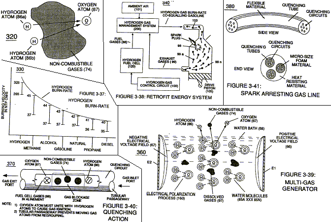
Dissolved air gases (97) of Figure (3-39) being uniformly released from water bath (85) via the Electrical Polarization Process (160) of Figure (3-26) is automatically intermixed with released hydrogen (86) and oxygen (87) gas atoms (also derived from water bath 85) to form Fuel-Gas mixture (88) of Figure (3-24) having a hydrogen gas burn-rate of approximately 47 centimetres per seconds (cm/see) in ambient air, as illustrated in (330) of Figure (3-37). Volatility of hydrogen fuelmixture or Fuel-Gas (88) is reduced from 325 cm/sec. to approximately 47 cm/sec. since ambient air gases (97) (dissolved air gases in water) is primarily composed of non-combustible gases (74) (such as nitrogen, argon, and other non-burnable gases) of Figure (3-39) which acts and performs as a “Gas Modulator” during thermal gas ignition (98), as illustrated in (320) of Figure (3-36). The non-combustible gases (74) physically retards and slows down the speed by which oxygen atom (87) unites with (covalent link up) hydrogen atoms ( 86a / 86b) to bring on and support gas ignition process (gas combustion process) (98), as further illustrated in (340) of Figure (3-38).
Water bath (68) of Figure (3-39) as to Figure (3-24), now, becomes and functions as a “Gas Mixing Regulator” since the highest possible thermal explosive energy yield (gtnt) obtainable from hydrogen during “normal” gas ignition (98) is the exact composition of water where two hydrogen atoms (86a / 86b) unite with oxygen atom (87).
Inherently, the utilization of the Electrical Polarization Process (160) of Figure (3-26) in conjunction with the use of chemically inert stainless steel (T304 material) voltage zones (EI / E2) submerged in natural water (68) sustains and maintains gas mixing ratio (88) by simply preventing the consumption of both the hydrogen (86) and oxygen (87) gases by way of not encouraging “electrical heat” or “chemical interaction” associated with amp consumption. Remember, Electrical Polarization Process (160) is a physical process which uses opposite electrical polarity attraction force (qq’) to perform work by disrupting and switching off the covalent bond between the unlikecharged water molecule atoms.
To further reduce hydrogen burn-rate (330) of Figure (3-37) to other fossil-fuel burning levels, additional non-combustible gases (99a xxx 99n) (supplied via ambient air 101 ) is added to gas-mixture (88) by way of gas ignition process (98) occurring inside internal combustion engine (55) piston cylinder (102), as illustrated in (340) of Figure (3-38). As fuel-gas (88) enters into engine cylinder (102) and is exposed to thermal gas ignition process (98), the incoming and moving fuel-gases (88) are converted into non-combustible gases (99) (gases passing through the gas combustion process) since both the hydrogen (86) and oxygen (87) gas atoms are being consumed during the formation of superheated water mist (103) … releasing thermal explosive energy (gtnt) which, in turns, causes piston-action to expel the newly formed non-combustible exhaust gases (99) for recycling.
The liberated and cooling exhaust gases (99) is, now, directed to hydrogen injector system (200) which systematically meter-mixes and superimposes a predetermined amount of non-burnable gases (99) of Figure (3-38) onto incoming ambient air gases (101) which is being directed to engine cylinder (102) to sustain and maintain both the “Gas Modulator Process” (320) of Figure (3-36) and the “Gas Ignition Process” (98), simultaneously. In essence, then, ambient air gases (101) becomes a endless supply of non-combustible gases (99A xxx 99n) during the gas ignition process.
The resultant and on-going Gas Modulator Process (320) of Figure (3-36),now, allows hydrogen fuel cell (120) of Figure (3-24) to be retrofitted to any conventional internal combustion engine (55) of Figure (3-1) without engine change by simply metering the proper amount of exhaust gases (99a xxx 99n) to comply with and co-equaling any type or different fossil-fuel burning levels, as further illustrated in (330) of Figure (3-37).
In terms of operability and performance, gas modulator process (320) continues to allow a conventional internal combustion engine (55) to run on ambient air gases; while, fuel-gas (88) not only cuts back and reduces oxygen extraction form ambient air (101) but produces a environmentally safe exhaust gases since non-combustible> gases (99/74) from both ambient air gases (101) and Fuel-Gas (88) are thermally inert to gas ignition process (98).
Gas Processor
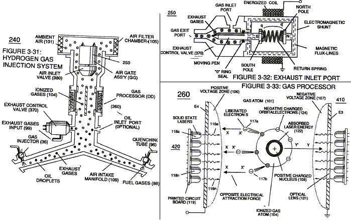
To obtain higher energy-yields beyond the normal gas combustion process, ionized ambient air gases (104) of Figure (3-31) is, now, exposed to and intermixed with Fuel-Gases (88) prior to thermal gas ignition (98) of Figure (3-38), as illustrated in (240) of Figure (3-31). As ambient air gases (l01) enters into and passes through air f1lter chamber (105) toward and beyond air gate assembly (GG), the moving air gases (101) are exposed to a high energy voltage fields (up to and beyond 2,000 volts) (106/107) of opposite electrical polarity which causes ambient air gases to become ionized gases (104), as illustrated in (260) of Figure (3-33). Positive electrical voltage field (106) causes negative charged orbital electrons (l24a xxx) to be ejected from gas atom (101) due to opposite electrical attraction force (xx’); while, at the same time, negative electrical voltage field (107) exerts a second electrical attraction force (yy’) on gas atom positive charged nucleus (108) … opposite electrical attraction forces (xx’) and (yy’) being of equal intensity, as further illustrated in (260) of Figure (3-33).
Once electron ejection occurs, the liberated and free floating electrons (117a xxx 117n) continues to migrate toward positive voltage zone (106); whereas, the newly formed ionized gas atom (having missing electrons) (104) continues to move onward and through air intake manifold (109) of Figure (3-31) to engine cylinder (102) of Figure (3-38).
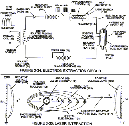
The resultant ionized gas process (260) of Figure (3-33) is performed by Electron Extraction Circuit (270) of Figure (3-34) which function in like manner to Voltage Intensifier Circuit (60) ofFi~ (3-22) except amp consuming device (390) (such as a light bulb _11_2 placed between Resonant Charging Choke (56) and Gas Resonant Cavity (410) of Figure (3-34) is added to pulsing circuit (60) to cause and convert liberated electrons (117a xxx 117n) into radiant heat – energy (Kinetic energy) (113) in the form of light energy (l14) … thereby preventing electrons (117a xxx 117n) from re-entering ionized gas process (260) … destabilizing gas atom (101).
Repetitive formation of electrical voltage force or voltage intensity (65a xxx 65n) of Figure (3-21) attracts and causes liberated electrons (117a,xxx 117n) to move electrically away from gas resonant cavity (410) and physically interact with light bulb filament (115) to initiate and perform kinetic conversion process (390), as further illustrated in (270) of Figure (3-34). The newly established and on-going electron conversion process (390) continues to aid ionized gas process (260) as other gas atoms (101a xxx l0In) are destabilized into ionized gas vapor (104a xxx 104n). The electron conversion process (390) is, of course, terminated when applied pulse voltage potential (65) is switched off. Pulsating voltage potential or voltage intensity (65a xx 65n) is adjusted, also, to “tune-in” to the resonant properties of ambient air gases (101) since ambient air gases (101) exhibits a dielectric value (air-gap of one inch resisting electron arc-over of up to 17,000 volts applied) between voltage plates (E3) and (E4), forming capacitor (410) of Figure (334).
Voltage fields (106/107) are physically configured (skin effect) by T304 stainless steel material to form voltage plates (E3!E4) of Figure (3-33) which are not only chemically inert to gas ionization process (260) but, also, forms tubular Gas Resonant Cavity (410) of Figure (3-34) having approximately the same size and shape of liquid resonant cavity (170) of Figure (3-25), as illustrated in (270) of Figure (3-34).
To further destabilize gas atom (104), emitted laser energy (electromagnetic energy having zero mass) (116) is, now, injected into Gas Resonant Cavity (410) via optical lens (121) and superimposed onto gas ionized process (260) and subsequently absorbed by gas atom nucleus (108), as illustrated in (260) of Figure (3-33) as to (270) of Figure (3-34). The absorbed laser energy (122) of Figure (3-35) not only causes ionized gas atom orbitals electrons (124) to be deflected away from gas atom nucleus (108) but, also, weakens electrostatic force (AA’) between gas atom nucleus (108) and deflecting electrons (123a xxx) … allowing even a greater number of electrons (117a xxx) to be ejected from ionized gas atom (104) being simultaneously subjected to Electron Extraction Process (260), as illustrated in (280) of Figure (3-35).
In essence, then, laser interaction (280) along with applied voltage process (260) causes gas atom (101) to go into sub-critical state (destabilizing the mass entity of a gas atom) since absorbed laser energy (122) prevents electrons re-capture (atoms accepting electrons) while interfacing circuit (270) dislodges, captures, and immediately consumes ejected electrons (117a xxx) In other words, ambient air gases (101) has, now, become a electromagnetically primed destabilized gas atoms (l04a xxx 100n) having missing electrons.
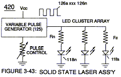
Solid state light-emitting diode (118) of Figure (3-33) arranged in a cluster-array (118a xxx 118n) mounted on printed circuit board (119) emits a discrete wave-length of light energy (electromagnetic energy) when light circuit assembly (420) of Figure (3-43) is electrically pulsed (126a xxx 126n) via variable pulsing circuit (125) in such a way as to vary light intensity (116) to match the light absorption rate of ionized gas (104), and, is determined with respect to the forward current through Led’s (118) by (Eq 15)
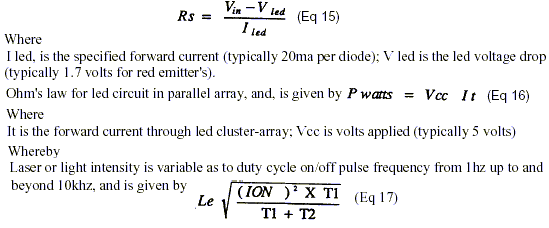
Le is light intensity in watts; Tl is current on-time; 1’2 is current off-time; and (ION) = RMS value of load current during on-period.
In terms of assembly, gas resonant cavity (410), electron extraction circuit (270), optical lens (121) forms gas processor (260) of Figure (3-31). In retrospect to operational parameters, led’s (118) light spectrum (extending from the visible into the Ultraviolet light region) can be selected for a given or predetermined electromagnetically gas priming application (280) since gas nucleus (108) is more responsive to coherent rather than diffused light source. Applied voltage amplitude (Va xxx Vn), applied voltage pulse frequency (65a xxx 65n), and applied current pulse train (126a xxx 126n) are design variable to “tune-in” to the resonant properties of gas atom (101) while stimulating and performing gas process (260) which attenuates electrical force (AA’) of Figure (3- 35) to disrupt the mass equilibrium of gas atom (104).
The resultant and newly formed sub-critical gas atoms (104a xxx l04n) are directed onward through air intake manifold (109) of Figure (3-31) to and beyond both exhaust gas metering port (370) and injector port (36) where metered fuel-gas (88), metered exhaust gases (99), and metered sub-critical gas atoms (l04a xxx l04n) forms gas-mixture (103) entering engine cylinder (102), as illustrated in (240) of Figure (3-31) as to (340) of Figure (3-38).
Hydrogen Fracturing Process
Incoming processed hydrogen fuel gas (103) is, now, exposed to thermal spark ignition process (98) which triggers thermal explosive energy-yield (gtnt) (127) that causes piston-action (105) of Figure (3-38) to exceed normal gas combustion process associated with hydrogen to air mixture of gases in stable state. Thermal atomic interaction (127) is caused when sub-critical gas ions (104a xxx 104n) (derived from both water bath ~ and ambient air gases 1Ql fails to unite with or covalently link up or covalent bond with highly energized (laser primed) hydrogen atom (128).Sub-critical Oxygen atom (129) having less than the normal amount of covalent electrons (orbital electrons) is unable to reach “stable-state” (six to eight covalent electrons required) when the two hydrogen atoms (128 a/b) seek to form the water molecule during thermal gas ignition.
Absorbed laser energy (131) of hydrogen gas atom nucleus (133) weakens “electrical bonding” force (CC’) between hydrogen atom electron (132) and hydrogen atom nucleus (133); while, at the same time, absorbed laser energy (135) prevents oxygen atom (129) from reaching “stable state” when electrical attraction force (BB’) (opposite electrical attraction force being equivalent to the number of missing electrons) locks onto and pulls away hydrogen atom electron (132) while repelling force (DD’) keeps the two positive charged nucleuses (133/136) apart. These “‘abnormal” and “unstable” conditions coupled with thermal interaction (gas ignition) under gas compression (137) of Figure (3-42) as to Figure (3-38) (fuel-gas 88 being compressed via piston-action 105) causes combustible gas atoms (129 and 128a/b) to decay … releasing thermal explosive energy (gtnt) (127) under control means. This atomic thermal-interaction between sub-critical combustible gas atoms (127 and 128a/b) is, now, herein after called “The Hydrogen fracturing Process. “
Laser Distributor
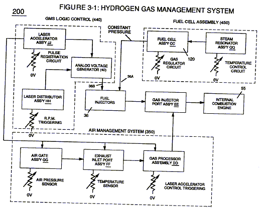
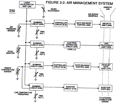
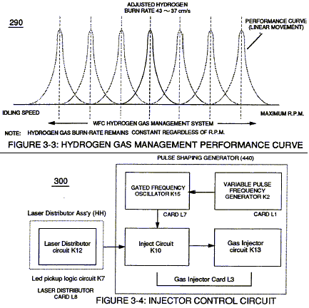
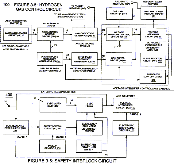
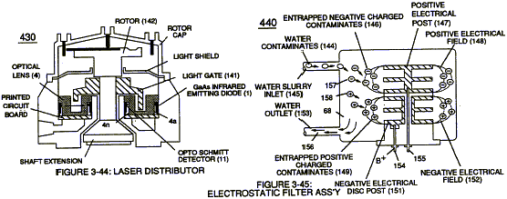
Laser Distributor assembly (430) of Figure (3-44) functions in similar manner as Laser Accelerator (20) of Figure (3-10) except light-gate (141) of Figure (3-44) rotates in the same direction of Spark, .rotor (142) and being displaced opposite to rotor blade (142), allowing intermixed process ambient air gases (101) and Fuel-Gases (88) to enter engine cylinder (102) of Figure (3-38), as illustrated in Injector Control Circuit (300) of Figure (3-4). Rotating light-gate triggering circuit assembly (430) sequentially activates Pulse Shaping Generator (440) of Figure (3- 4) to produce a constant 50% Duty-cycle Pulse- Train (see Figure 3-16 once again) to Analog voltage Generator (40) of Hydrogen Gas Management System (200) of Figure (3-1) as to Figure (3-5). Interlocking Laser Accelerator output}1{JJ) with Laser Distributor output (HH) of Figure (3-~1) causes Fuel-Injectors (36) to be “Tuned” with both Air Management System (350) of Figure (3- 2) and Hydrogen Gas Control Circuit (100) of Figure (3-5) to maintain constant Fuel-mixing Ratio (290) of Figure (3-3) during engine performance. As Laser Accelerator (JJ) advances toward “Peak” engine performance, Fuel-Injectors (36) open gate-time (on-time) increases proportionally.
Opposite or reverse movement of Laser Accelerator (JI) decreases Injectors (36) on-time which, in turns, reduces engine speed.
Impurity Extraction Process
Suspended and dissolved water contaminates (l44a xxx 144n) (typically 20 ppm to 40 ppm in natural water) of Figure (3-24) being uniformly released from and superimposed onto remaining water bath (68) during Resonant Action (170) are directed to and passes through water inlet line (145) … causing liberated, moving, and free-floating micro-sized contaminates (144a xxx 144n) to be deposited inside Electrostatic Filter Assembly (440) and subsequently exposed to opposite electrical voltage fields (148/152), as so illustrated in Figure (3-45).
Negative electrically charged contaminates (157a xxx 157n) migrates to and entrapped by positive electrical voltage post (147); while, simultaneously, positive electrical charged contaminates (158a xxx 158n) are attracted to and entrapped by negative electrical voltage post (151) … thereby, extracting contaminates (144a xxx 144n) from water bath (68) … producing purified water bath (156) which is recycled back into Fuel Cell (120) of Figure (3-24) since Resonant Action (170) also function as and performs as a water>pump (Gas rising).
Exposing water contaminates (l44a xxx 144n) to applied voltage fields (EIIE2) not only produces electrical charged contaminates (157/158); but, also, kills bacteria that might be present in water bath (68). Periodically back-flushing (rinsing out) is all that is require to ensure and sustai Electrostatic Filter Process (440).
Steam Resonator
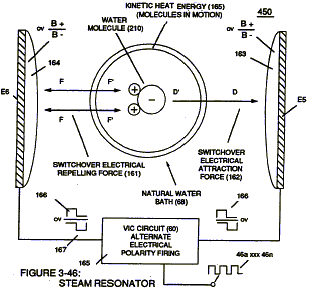
To further ensure proper Fuel Cell optional performance during frigid or below freezing weather conditions, Steam Resonator assembly (450) of Figure (3-46) is inserted into Fuel Cell (120) of Figure (3-24) and thermos . ally activated via Voltage Intensifier Circuit (165) which directly applies an alternate or opposite (166/167) electrical voltage pulses (during amp restriction) in a sequential manner across voltage plates E51E6.
Once positive energized, water molecule (210) of water bath (68) is deflected toward voltage surface (E5) via both opposite electrical attraction force (162) and electrical repelling force (161). By simply reversing to a negative voltage pulse (167),now, causes water molecule (210) to be deflected in the opposite direction toward voltage surface (E6) … producing kinetic energy (165) (panicle impact) which, in turns, heats water bath (68). Repetitive formation of opposite voltage pulses (166/167) at a given pulse-frequency continues to heat water bath (68) until a desired temperature is reach.
Diesel Application
By simply adjusting Fuel-gases (88) of figure (3-38) burn-rate (330) of Figure (3-37) from (43 – 37 cm/s) (Gasoline) to (40 – 35 cm/s) (Diesel) burning levels, now, allows WFC Hydrogen Gas Management System to be directly retrofitted to conventional Diesel Engines since the newly established modulated Hydrogen Fuel-mixture (88 – Diesel) co-equals spark-ignition ratio (typically .35 -.39 ) of standard Diesel-Fuel (Fossil) under compression.
Aviation Application
Likewise, WFC Hydrogen Gas Management System is ideally suited as a retrofit energy system to both reciprocating and jet engines associated with the aviation industry … but in different ways: reciprocating WFC Fuel-kits can be similar to Car design (340); whereas, Water Fuel Injector kits (10) of figure (4-1) can alternately be used as a self-contained Fuel-unit having no prepressurized vessel which converts water directly in thermal explosive energy (gtnt) on demand, as illustrated in WFC memo 423 DA.
In terms of mechanical interfacing: Water Fuel Injector Assembly (10) of Figure (4-1) can replace standard fuel-injector ports of existing jet engines as shown in (150) of Figure (4-13); or be utilized in Furnace Nozzle Assembly (140) of Figure (4-12) for grain dryers or conventional heating systems; or be used to produce.rocket-thrust, as illustrated in (160) of Figure (4-14); or be used as a spark plug injector nozzle (130) of Figure (4-11) for both gasoline and diesel engines … to mention a few.
Operational Parameters
Coupling and subsequently integrating Hydrogen Gas Management (GMS) system (440) with either Hydrogen Fuel-Gas Assembly (450) of Figure (3-1) or Water Fuel Injector Assembly (10) of Figure (4-1) as to Water Fuel Management (WFMS) System (40) of Figure (4-2), now, sets up a full engineering system-approach on how to use Water as a “New” fuel-source. It’s design concept and system application complies with the “laws of economics” since micro-chip electronics and plastic mold injection technology help ensure performance reliability and usage … especially since Fuel Cell (120) of Figure (3-24) is miniaturized to Water Fuel Injector Plug (40) of Figure (4- 2), as further illustrated in WFC memo 423 DA.
